Table of Contents
Advertisement
Quick Links
Installation, Operation and Maintenance
CATEGORY I NATURAL GAS AND LP GAS
HIGH EFFICIENCY
TWO STAGE VARIABLE SPEED
WARM AIR FURNACE
MODEL 7 7 FV 95 A054 FV 95 A072 <
FV 95 A0 90
For future reference write down the model, serial
number, and date of purchase. Use these numbers in
any correspondence or service calls concerning your
furnace.
Model
Serial Number
Date of Purchase
Keep these instructions for future reference.
Please read the operating instructions and safety
precautions carefully and thoroughly before installing
and operating your furnace. Keep this manual in a
safe place for future reference.
USER'S INSTRUCTION GUIDE
LOCATED AFTER PAGE 43 OF THIS
INSTALLATION, OPERATION AND
MAINTENANCE MANUAL
FV 95 A108
<
23-23-0508N-003
Advertisement
Chapters
Table of Contents

Related Manuals for Fedders FV95A054


Summary of Contents for Fedders FV95A054
- Page 1 Installation, Operation and Maintenance CATEGORY I NATURAL GAS AND LP GAS HIGH EFFICIENCY TWO STAGE VARIABLE SPEED WARM AIR FURNACE MODEL 7 7 FV 95 A054 FV 95 A072 < FV 95 A0 90 FV 95 A108 < For future reference write down the model, serial number, and date of purchase.
-
Page 2: Table Of Contents
Table of Contents GAS SUPPLY ................28 INTRODUCTION ............... 1 AFETY ..................1 Gas Piping ..............28 afety Rules ..............1 Leak Testing ..............28 ODES..................3 High Altitude ..............29 FURNACE SIZING ..............4 CONVERSIONS ................. 29 AIR CONDITIONING .............. -
Page 3: Introduction
INTRODUCTION 6. Always install furnace to operate within the furnace’s intended temperature rise range with a duct system This 95% efficient gas fired furnace series is CGA / AGA which has an external static pressure within the esign certified as a Category I (condensing with positive allowable range, as specified in the Furnace Sizing vent pressure) non-direct or direct vent central forced air fur- section on page 4, the Ductwork section on page 7, and... - Page 4 DANGER DANGER WHAT TO DO IF YOU SMELL GAS: WHEN THIS FURNACE IS INSTALLED IN A RESIDENTIAL GARAGE, IT MUST BE INSTALLED SO THE BURNERS AND • DO NOT TRY TO LIGHT ANY APPLIANCE IGNITION SOURCE ARE LOCATED NO LESS THAN 18 •...
-
Page 5: Codes
with an alarm is installed on each additional level of CODES: the dwelling, building or structure served by the side wall horizontal vented gas fueled equipment. It shall This furnace must be installed: be the responsibility of the property owner to secure •... -
Page 6: Furnace Sizing
Existing ductwork should be assessed for its air handling FURNACE SIZING capabilities. For residential applications, the recommended The maximum hourly heat loss for each heated space shall air velocity of a supply air trunk duct is 700 feet per minute be calculated in accordance with the procedures described (fpm), and should not exceed 900 fpm. -
Page 7: Location Of Unit
LOCATION of UNIT Other Considerations: General 1. This furnace is not to be used for temporary heating of buildings or structures under construction. 1. The furnace is not weatherized. Select a dry indoor location. 2. If this furnace is to be used with air conditioning and is to be installed in an area over a finished ceiling or 2. -
Page 8: Clearances
CLEARANCES FIGURE 2: DIMENSIONS Table 2 provides the certified clearances to combustibles. IMPORTANT This furnace requires a minimum of 24-inches of front clearance for service purposes. For this purpose, service clearance takes precedence over clearance combustibles. TABLE 2: CLEARANCES TO COMBUSTIBLES HORIZONTAL UPFLOW COUNTERFLOW... -
Page 9: Ductwork
DUCTWORK WARNING Proper airflow is required for the correct operation of this DO NOT, UNDER ANY CIRCUMSTANCES, CONNECT furnace. Insufficient airflow may cause erratic operation, RETURN OR SUPPLY AIR DUCTWORK TO OR FROM ANY could cause the furnace to cycle on the high temperature OTHER HEAT-PRODUCING DEVICE SUCH AS A FIREPLACE limit, and may damage the heat exchanger. -
Page 10: Installation Positions
INSTALLATION POSITIONS IMPORTANT The furnace can be installed in any of four positions: Clean and de-burr all pipe cuts. The shavings must not • Upflow be allowed to block the exhaust, combustion air inlet or condensate drain lines. • Downflow •... -
Page 11: Inducer Blower Rotation
Instructions for Re-orienting Air Inducer This furnace comes assembled ready for left side or vertical FIGURE A : RIGHT INDUCER POSITION venting. Rotate the inducer 180 degrees to exit the right hand side. 1. Disconnect inducer wire connections. 2. Remove pressure switch hoses. 3. -
Page 12: Upflow Installation
Upflow Installation The combustion air and exhaust vent may exit through the top, left or right side of the cabinet when viewed in the upflow position. The inducer is installed so that the exhaust vent may exit the top and left sides without requiring rotation. -
Page 13: Downflow Installation
Downflow Installation The opening in the floor must provide adequate clearances When the furnace is installed in the downflow position to the combustible material. the combustion air and exhaust vent may exit through A half-inch of clearance will be required between the the left or right side of the cabinet (when viewed in the plenum and the combustible material. -
Page 14: Horizontal Installation
Horizontal Left Installation Horizontal Right Installation In the horizontal left installation the combustion air and In the horizontal right installation the combustion air exhaust vent may exit through the top or left side of the and exhaust vent may exit through the top or right side cabinet (when viewed in the upflow position). -
Page 15: Air For Combustion
CASE 1: CASE 3: FURNACE LOCATED IN AN UNCONFINED SPACE FURNACE LOCATED IN A CONFINED SPACE, OUT- DOOR Unconfined space does not necessarily mean that combus- tion and ventilation will not have to be introduced from AIR FROM ATTIC OR CRAWL SPACE the outdoors, particularly in airtight homes. -
Page 16: Furnace Venting
FURNACE VENTING DANGER Direct Venting Pipe Connections The following types of installation sites (but not limited to the following) will require OUTDOOR AIR for (USING OUTDOOR COMBUSTION AIR) combustion because of chemical exposures: commercial buildings, buildings with indoor swimming pools, The direct vent configuration is the preferred instal- furnaces installed in laundry rooms, furnaces in hobby lation method. -
Page 17: Air Filters
Air Filters Exhaust Vent Piping IAQ types of air filters may cause higher static, higher WARNING temperature rise and erratic furnace operation and, with an ECM drive, can cause blower over speed more noise. Also NEVER ALLOW THE PRODUCTS OF COMBUSTION FROM the consumer may at some time want to add UV treatment, THE FLUE TO ENTER THE RETURN AIR OR SUPPLY AIR and electrostatic air cleaners or HEPA filters. -
Page 18: Guidelines
JOINING PIPE AND FITTINGS CAUTION Acceptable Materials for Combustion Air and FAILURE TO FOLLOW ALL VENTING GUIDELINES MAY Exhaust Vent Pipe RESULT IN ERRATIC FURNACE OPERATION, FREEZE-UP OF THE VENTILATION AIR PIPING, OR SOOTING OF THE The furnace products of combustion include both flue FURNACE. -
Page 19: Direct Vent Piping Termination
PROCEDURE: Direct Vent Piping Termination This guide is intended specifically for PVC pipe; however, the general procedure applies to all plastic piping systems. CAUTION MATERIALS: PVC Cleaner / Primer and PVC Solvent Cement. Moisture in the flue gases condenses as it leaves the terminal. -
Page 20: Calculating Piping Length
Recommended clearance for overhangs is a minimum of 1 foot vertically for each foot horizontally up to 6 feet. As a protection against freezing, do not expose a 3 x 2 reducing coupling to outdoor ambient temperatures. Any adjacent painted surfaces should be in good condition; no cracks, peeling paint, etc. -
Page 21: Termination Of Combustion Air And Ventilation Pipe Using Aconcentric Venting Kit
TERMINATION OF COMBUSTION AIR AND VENTILATION PIPE USING A CONCENTRIC VENTING KIT Concentric venting terminal kits may be used for this series The concentric venting terminal has the combustion air intake furnace. They provide a means of obtaining combustion air built into the assembly. -
Page 22: Horizontal Termination Of Combustion Air And Exhaust Vent
HORIZONTAL TERMINATION OF COMBUSTION AIR AND EXHAUST VENT Horizontal Combustion Air Termination If the required clearance to grade or anticipated snow level cannot be obtained with the “straight through” The combustion air termination is a 2” medium or long configuration, the exhaust pipe may be “periscoped” up to sweep 90°... -
Page 23: Vertical Termination Of Combustion Air And Exhaust Vent
VERTICAL TERMINATION OF MULTIPLE VENTING COMBUSTION AIR IMPORTANT AND EXHAUST VENT When installing multiple furnaces in close proximity, TOP VIEW each requires dedicated combustion air and exhaust venting. Vertical Combustion Air Termination The combustion air termination is a pair of 2” medium or long sweep 90°... -
Page 24: Non Direct Vent Furnace Installations
NON-DIRECT VENT FURNACE IMPORTANT INSTALLATIONS If the furnace is to be installed in the vicinity of other (USING INDOOR COMBUSTION AIR) fuel burning appliances, adequate combustion air must be available for the non-direct vent appliances. The furnace, although designed as a direct vent type See Section 10 of this manual, “Determining appliance, may be installed with the intake vent inside Combustion Air.”... - Page 25 Other Then Direct Vent Terminal Clearances Canadian Installations US Installations = Clearance above grade, veranda, 12 in (30 cm) 12 in (30 cm) porch, deck, or balcony = Clearance to window or door that 6 in (15 cm) for appliances 10,000 4 ft (121 cm) below or to side of may be opened Btuh (3 kW), 12 in (30 cm) for...
- Page 26 Direct Vent Terminal Clearances Canadian Installations US Installations = Clearance above grade, veranda, 12 in (30 cm) 12 in ( 30cm ) porch, deck, or balcony = Clearance to window or door that 6 in (15 cm) for appliances 10,000 6 in (15 cm) for appliances 10,000 may be opened Btuh (3 kW),12 in (30 cm) for...
-
Page 27: Condensate Drains
CONDENSATE DRAINS DRAIN PIPING Condensate from the outlet of the drain trap assembly The furnace will condense as much as a half pound of must be conveyed to a floor drain, sump pit, or, if these are water per hour (approximately 2 imperial quarts, 2 U.S. - Page 28 HORIZONTAL FLOW LEFT HORIZONTAL FLOW RIGHT CONDENSATE TRAP CONDENSATE TRAP FIGURE 11 FIGURE 12 DOWNFLOW UPFLOW CONDENSATE TRAP CONDENSATE TRAP FIGURE 14 FIGURE 13...
-
Page 29: Condensate Drain Installation
CONDENSATE DRAIN INSTALLATION Identify which side the condensate drain trap will be installed on the unit. Condensate trap may be mount- ed on either the left or right side of the unit, when looking at the front. Some installation positions will only allow one option to mount the drain. -
Page 30: Gas Supply
Install a manual gas shutoff valve and drip leg as close to GAS SUPPLY the furnace as possible. Some local codes call for the manual gas shutoff valve to be located between 4 to 5 feet WARNING above floor level to prevent tampering by small children. THIS FURNACE IS FACTORY EQUIPPED TO BURN NATURAL Ensure that the valve is readily accessible. -
Page 31: High Altitude
Gas piping that has not been pressure tested, from the Conversion Steps manual shutoff valve to the furnace gas valve for example, To convert from sea level to high altitude, from natural gas should be leak tested using an electronic combustible gas to L.P. -
Page 32: High Altitude & Airflow Specification Tables
For USA HIGH ALTITUDE SPECIFICATIONS High Fire Low Fire Orifice Rating Plate Input BTU/hr Altitude(ft) Input Output Input Output Natural Gas LP Gas (BTU/hr) (BTU/hr) (BTU/hr) (BTU/hr) (mm)* (mm)** 0-2000 54000 51300 35100 33350 1.95mm 1.20mm 2000-3000 47520 45144 30888 29344 1.90mm 1.15mm... - Page 33 12. Turn outlet pressure tap screw clockwise to seal the pressure point using the supplied hex wrench. Tighten SETTING THE MANIFOLD (Outlet) GAS PRESSURE to 13 in-lbs. minimum. Return all pressure regulator (F92-1003 36G Valve Pressure Check Kit) caps. The manifold outlet pressure is specified on the rating 13.
-
Page 34: Electrical Specifications
IMPORTANT ELECTRICAL SPECIFICATIONS USE COPPER CONDUCTORS ONLY Before proceeding with the electrical connections, ensure that the available electrical supply is compatible with the If the junction box must be moved to the right hand side: voltage, frequency, and phase listed on the appliance rating plate. -
Page 35: Thermostat
WARNING ISOLATION RELAY Make adjustments to the controller with the electrical power off. THERMOSTAT COOLING START UP PROCEDURES CONTACTOR This furnace is equipped with a hot surface ignition (HSI) device. Each time that the room thermostat calls for heat, the HSI lights the main burners directly. See the lighting instructions on the furnace. -
Page 36: Sequence Of Operation If The Furnace Does Not Light Or Detect Flame
6. The circulating fan begins 30 seconds after flame is 5. After the prepurge period, and after pressure switch sensed. contacts have closed, the hot surface igniter heats up; 5 seconds on a first try, 10 seconds on a subsequent 7. -
Page 37: Circulating Air Blower And Temperature Rise Check
The formula for determining the furnace input via the gas A temperature rise within 35-65 degrees F is acceptable meter test dial is: when the furnace is operating with both stages of heat on. If a higher temperature rise is desired, refer to the dip switch settings for “Heating”. -
Page 38: Adjusting Dip Switches
DIP Switch Configurations AC Tonnage Heating Cool Switch Rise Rating Plate Rating Plate Jumper Jumper ADJUST ADJUST Description Input BTU/hr Input BTU/hr (NORM) ( - ) 54,000 Cool 54,000 72,000 72,000 Cool Cool 90,000 90,000 108,000 108,000 Cool To obtain the correct airflow for the cooling mode, please refer to the table above. Note the position of the delay tap. -
Page 39: Adjusting Blower Speeds
Delay 1150 delay delay 70-4 Cool 1000 ADJUSTING BLOWER SPEEDS How To Install The Blower Place blower into blower compartment. Cooling Mode Switch 2. Keep blower assembly tight to top of blower The unit is factory set to provide the highest airflow. 1550 Model compartment. -
Page 40: Maintenance
TABLE 8 MAINTENANCE Avoid placing heat producing appliances such as televisions, radios, lamps, etc. in a location to influence WARNING the thermostat. DISCONNECT THE ELECTRICAL POWER SUPPLY TO THE Keep combustible articles at least 3 feet away from the FURNACE BEFORE ATTEMPTING ANY MAINTENANCE. furnace. -
Page 41: Electrical
Electrical WARNING WARNING ALL WIRING INSIDE THE FURNACE MUST HAVE A DISCONNECT THE ELECTRICAL POWER SUPPLY TO THE MINIMUM TEMPERATURE RATING OF 105C. FURNACE BEFORE ATTEMPTING THIS MAINTENANCE PROCEDURE. FAILURE CAUSE ELECTRICAL SHOCK RESULTING IN PERSONAL INJURY OR Troubleshooting LOSS OF LIFE. Page 41, Table 9, Page 42, Table 10 and Figure (trouble shooting) will aid in trouble shooting. - Page 43 TABLE 9 LED FLASH(ES) NDICATES (FEDDERS UTEC 1170-25 CONTROLLER) CHECK and REPAIR Green Off Internal controller or Room Air Fan failure. 1. Replace Integrated Furnace Control. DO NOT operate on heat until Fan failure cleared. 2. Rollouts or Fan failure– see 5 Red Roll-out open.
- Page 44 TABLE 10 : GENERAL TROUBLESHOOTING INTEGRATED FAN CONTROL CHECK or REPAIR Induced blower wiring. Induced blower does 3 Flash code does not come on not energize Induced blower. Pressure switch stuck closed. Induced blower does 3 Flash code does come on not energize Pressure switch is mis-wired or jumpered.
- Page 46 User’s Information Manual TABLE OF CONTENTS WARNING FURNACE COMPONENTS ....1 WHAT TO DO IF YOU SMELL GAS: • DO NOT TRY TO LIGHT ANY APPLIANCE REGULATOR VENT .
-
Page 47: Furnace Components
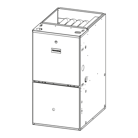
FURNACE COMPONENTS GENERAL SAFETY RULES 1. Combustible materials should not be stored against or FIGURE 1 around the furnace. Keep the furnace area clear and FURNACE COMPONENTS free from all combustible materials such as newspapers, rags, cardboard, clothing, etc. This applies especially to gasoline and other flammable vapors and liquids. -
Page 48: Furnace Operation Information
FURNACE OPERATION INFORMATION Furnace Shutdown Procedure During the heating season, the operation of the furnace is 1. Set the thermostat to its lowest setting. fully automatic. 2. Shut off electric power to the furnace. To Start The Furnace: 3. Turn the appliance manual shutoff valve to the "OFF" position. -
Page 49: Maintenance
MAINTENANCE • The furnace should be well supported on a level floor or by the means used to suspend the furnace in a horizontal Replacing Air Filter configuration. Base support should be physically sound Disconnect electrical power to the furnace. without sagging, cracks, gaps, etc. -
Page 50: Sequence Of Operation
Illustrations cover the general appearance of the units at the time of publication and the manufacturer reserves the right to make changes in design and construction at any time without notice. For replacement parts contact: Airwell Fedders North America 2 Centre Drive, Monroe Township, NJ 08831 Phone: 1-800-332-6658...
Need help?
Do you have a question about the FV95A054 and is the answer not in the manual?
Questions and answers