Empire Comfort Systems DVP42FP3(0,1,2,3)(N,P)-1 Installation Instructions And Owner's Manual
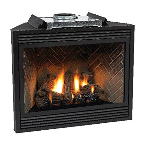
The tahoe direct vent zero clearance gas fireplace heater
Hide thumbs
Also See for DVP42FP3(0,1,2,3)(N,P)-1:
- Installation instructions and owner's manual (80 pages)
Table of Contents
Advertisement
The Tahoe Direct Vent Zero Clearance
Gas Fireplace Heater
Installer: Leave these instructions with the
consumer.
Consumer: Retain these instructions for future
use.
Warning: If the information in this manual is not fol-
lowed exactly, a fire or explosion may result causing
property damage, personal injury or loss of life.
- Do not store or use gasoline or other flammable
vapors and liquids in the vicinity of this or any
other appliance.
- WHAT TO DO IF YOU SMELL GAS
● Do not try to light any appliance.
● Do not touch any electrical switch; do not use
any phone in your building.
● Immediately call your gas supplier from a
neighbors phone. Follow the gas supplier's
instructions.
● If you cannot reach your gas supplier, call the
fire department.
- Installation and service must be performed by
a qualified installer, service agency, or the gas
supplier.
17375-10-0706
INSTALLATION INSTRUCTIONS
OWNER'S MANUAL
UL FILE NO. MH30033
This appliance may be installed in an aftermarket,
permanently located, manufactured home (USA only)
or mobile home, where not prohibited by state or local
codes.
This appliance is only for use with the type of gas
indicated on the rating plate. This appliance is not
convertible for use with other gases, unless a certified
kit is used.
WARNING: If not installed, operated and maintained
in accordance with the manufacturer's instructions,
this product could expose you to substances in fuel or
from fuel combustion which can cause death or seri-
ous illness.
AND
DIRECT VENT
GAS FIREPLACE HEATER
MODEL SERIES
MILLIVOLT STANDING PILOT
DVP42FP3(0,1,2,3)(N,P)-1
DVP48FP3(0,1,2,3)(N,P)-1
INTERMITTENT PILOT
DVP42FP7(0,1,2,3)(N,P)-1
DVP48FP7(0,1,2,3)(N,P)-1
REMOTE RF MODELS
DVP42FP9(1,3)(N,P)-1
DVP48FP9(1,3)(N,P)-1
GAS-FIRED
EFFECTIVE DATE
JULY 2006
Page 1
Advertisement
Table of Contents
Troubleshooting

Related Manuals for Empire Comfort Systems DVP42FP3(0,1,2,3)(N,P)-1


Summary of Contents for Empire Comfort Systems DVP42FP3(0,1,2,3)(N,P)-1
-
Page 1: Installation Instructions
INSTALLATION INSTRUCTIONS OWNER’S MANUAL The Tahoe Direct Vent Zero Clearance DIRECT VENT Gas Fireplace Heater GAS FIREPLACE HEATER MODEL SERIES MILLIVOLT STANDING PILOT DVP42FP3(0,1,2,3)(N,P)-1 DVP48FP3(0,1,2,3)(N,P)-1 INTERMITTENT PILOT DVP42FP7(0,1,2,3)(N,P)-1 DVP48FP7(0,1,2,3)(N,P)-1 REMOTE RF MODELS DVP42FP9(1,3)(N,P)-1 DVP48FP9(1,3)(N,P)-1 GAS-FIRED EFFECTIVE DATE Installer: Leave these instructions with the JULY 2006 consumer. -
Page 2: Table Of Contents
MAIN TITLE Section Page Important Safety Information ......................3 Safety Information for Users of LP Gas ..................4 Requirements for Massachusetts ....................5 Introduction ........................... 6 Specifications ..........................7 Fireplace Dimensions ........................7 Clearances ............................8 Locating Fireplace .......................... 8 Gas Supply ............................. -
Page 3: Important Safety Information
IMPORTANT SAFETY INFORMATION Before enclosing the vent pipe assembly, operate the appliance to ensure it is venting properly. DO NOT OPERATE THIS APPLIANCE WITHOUT GLASS FRONT PANEL INSTALLED • If this appliance is installed directly on carpeting, tile • This appliance must not share or be connected to a flue or other combustible material other than wood flooring serving a separate solid-fuel burning appliance. -
Page 4: Safety Information For Users Of Lp Gas
SAFETY INFORMATION FOR USERS OF LP GAS Propane (LP-Gas) is a flammable gas which can cause fires by point with the members of your household. Someday when and explosions. In its natural state, propane is odorless and there may not be a minute to lose, everyone’s safety will depend colorless. -
Page 5: Requirements For Massachusetts
REQUIREMENTS FOR MASSACHUSETTS For all side wall horizontally vented gas fueled equipment installed 3. SIGNAGE. A metal or plastic identification plate shall be in every dwelling, building or structure used in whole or in part permanently mounted to the exterior of the building at a for residential purposes, including those owned or operated by the minimum height of eight (8) feet above grade directly in line Commonwealth and where the side wall exhaust vent termination... -
Page 6: Introduction
(a) the installation or replacement of gas piping or (b) the • Modification of the fireplace or direct vent system. connection, installation, repair or servicing of equipment, who is • Installation other than as instructed by Empire Comfort Systems, experienced in such work, familiar with all precautions required Inc. -
Page 7: Specifications
SPECIFICATIONS DVP42 DVP48 Input Btu/hr Maximum 28,000 30,000 Btu/hr Minimum (millivolt only) 19,000 20,500 KWH (Maximum) (Minimum) NOTE: Air shutter settings NAT. are factory minimum settings. #38 (.1015) Orifice #37 (.1040) P-213 Some venting configurations P-203 may require minor air shutter Air Shutter Opening 1/8"(3.2mm) 1/8"(3.2mm) -
Page 8: Clearances
CLEARANCES Mantel Chart (Figure 3) Clearance to Combustibles Back 0" (0 mm) 12” (305mm) 10” (254mm) Side 0" (0 mm) Floor 0" (0 mm) MANTEL Top Stand-off 0" (0 mm) COMBUSTIBLE TRIM AND MANTELS 8” Top Framing Edge 3" (76 mm) ALLOWED IN SHADED AREA 15”... -
Page 9: Gas Supply
GAS SUPPLY Installing a New Main Gas Cock The gas pipeline can be brought in through the right or left side of the appliance. Consult the current National Fuel Gas Code, ANSI Each appliance should have its own manual gas cock. Z223.1 CAN/CGA-B149 (.1 or .2) installation code. -
Page 10: Rear Vent Conversion/Vent Systems
REAR VENT CONVERSION VERTICAL VENTING Note: Discard insulation HORIZONTAL VENTING & retainer when venting off top of fireplace. INLET VENT Note : Discard insulation COVER PLATE & retainer when using vertical venting off Note : It is recommended that the FLUE COVER PLATE flue cover plate tab be pulled outward prior to removal. -
Page 11: Installation
INSTALLATION Framing and Finishing 1. Choose unit location. 2. Frame in fireplace with a header across the top. It is important to allow for finished face when setting the depth of the frame. 3. Attach fireplace to frame using adjustable frame. Preset depth to suit facing material (adjustable to 1/2", 5/8"... - Page 12 INSTALLATION (continued) Flush Mount Mantel Installation (Figure 10) The fireplace must extend 3/4" beyond finished wall surface when using a flush mount mantel. Refer to Figure 10 to locate nailing flanges on fireplace sides. Mark and drill two (2) 1/8" holes into fireplace side to mount each nailing flange.
- Page 13 Flush Wall Installation Attention: Cold climate installation recommendation: FINISHED WALL When installing this unit against a non-insulated exterior wall, it is recommended that the outer walls be insulated to 3! OF NON-COMBUSTIBLE MATERIAL conform to applicable insulation codes. FRONT TRIM OR NON- COMBUSTIBLE MA TERIAL (INSTALLA TION IS OPTIONAL) Vent Runs (Figures 14, 15, 16, 17 and 18)
- Page 14 INSTALLATION (continued) HORIZONTAL ONLY, STRAIGHT OUT THE BACK CORNER INSTALLATION VERTICAL, 90° ELBOW TO HORIZONTAL OUT THE WALL " A" WALL FIRESTOP/ PIPE LENGTH THIMBLE VENT VENT CAP WALL FIRESTOP/ THIMBLE Dim. DVP42 DVP48 "A" "B" MODEL 45 3/8" 49 5/8" 6"(152mm) 5 1/8"(130mm) to 6 /2"(165mm) DVP 42,48...
-
Page 15: Venting Fireplace-Top Vent
VENTING FIREPLACE - TOP Venting Graph (Dimensions in Feet) To Use the Vent Graph (Figure 19) 1. Determine the height of the center of the horizontal vent pipe. Using this dimension on the Sidewall Vent Graph, locate the point it intersects with the slanted graph line. - Page 16 VENTING FIREPLACE - TOP (continued) Below Grade Installation When it is not possible to meet the required vent terminal clearances of 12" (305mm) above grade level, a snorkel kit is recommended. It allows installation depth down to 7" (178mm) below grade level. The 7"...
- Page 17 minimum O F E L B C E N T E R H T O U T S T R A I G ( M I N I M U Figure 24 Figure 23 MINIMUM HOLE LOCATION DIMENSIONS FOR THROUGH THE WALL HORIZONTAL INSTALLATIONS MAXIMUM HORIZONTAL WITH 90 DEGREE ELBOW OFF TOP OF FIREPLACE RUN WITH NO VERTICAL...
- Page 18 EXAMPLES - TOP VENT RUN 24” 24” MINIMUM CLEARANCE TO COMBUSTIBLES Figure 27 Figure 26 Figure 28 Page 18 17375-10-0706...
-
Page 19: Venting Fireplace-Rear Vent
VENTING FIREPLACE - REAR Venting Graph (Dimensions in Feet) To Use the Vent Graph (Figure 29) 1. Determine the height of the center of the REAR EXIT - VERTICAL AND HORIZONTAL TERMINATION horizontal vent pipe. Using this dimension on (DIMENSIONS IN FEET) the Sidewall Vent Graph, locate the point it intersects with the slanted graph line. - Page 20 EXAMPLES - REAR VENT RUN Model Maximum Pipe Length H1 DVP42 24" DVP48 6" Figure 32 Figure 30 Model Maximum Pipe Length H1 DVP42 24" DVP48 18" Figure 31 Figure 33 Page 20 17375-10-0706...
-
Page 21: Termination Clearances
TERMINATION CLEARANCES Termination clearance for buildings with combustible and noncombustible exteriors. Figure 34 Vertical Sidewall Installations Important! Minimum clearance between vent pipes and combustible materials is three (3") (76mm) on top, and (1") (25mm) on bottom and sides. Important! When vent termination exits through foundation less than 20" below siding outcrop, the vent pipe must flush up with the siding. -
Page 22: Vent Clearances
VENT CLEARANCES Figure 35 *Clearance above grade, veranda, porch, deck or balcony clearance to non-mechanical air supply inlet to building or [*12 inches (30cm) minimum] the combustion air inlet to any other appliance [*12 inches (30cm) minimum for appliances ≤ 100,000 Btuh (30 kW) clearance to window or door that may be opened [*12 inches (30cm) minimum for appliances <... -
Page 23: Vent System Identification
Adjustable Pipe Length 11 - 14 5/8" SD-1284 Horizontal Square Termination Cap SD-1250 Vinyl Siding Standoff Special DV Vent Kits - Simpson Duravent and Empire Comfort Systems, Inc. SD-1245 45° Elbow Can be purchased from Empire Comfort Systems, Inc. SD-1290 90°... -
Page 24: Framing And Finishing
FRAMING AND FINISHING Installing Support Brackets (Figure 37) A horizontal pipe support MUST BE used for each 3 feet of horizontal run. The pipe supports should be placed around the pipe and nailed in place to framing members. There MUST BE a 3 inch clearance to combustibles above 8 inch diameter pipe and elbows and 1 inch clearance on both sides and bottom of the 8 inch dia. -
Page 25: Horizontal Termination
FRAMING AND FINISHING (continued) Figure 39 Figure 41 See Horizontal Termination Page 25 and Vertical Termination Page 27-28. Figure 40 HORIZONTAL TERMINATION NOTE: Termination cap should pass through the wall firestop from the exterior of the building. Adjust the termination cap to its final exterior position on the building. -
Page 26: Dvvk-5F Flex Vent
DVVK-5F FLEX VENT INSTRUCTIONS The DVVK-5F FLEX VENT KIT includes the following components: • (1) Horizontal Termination Cap with flue adapter collar • (1) 4-foot section of Flex vent with spacers (5" flue/8" • (1) Wall Firestop/Thimble Assembly outer pipe) •... -
Page 27: Vertical Termination
VERTICAL TERMINATION Locate and mark the center point of the venting pipe. Using a nail 2. Remove the cap and shine a flashlight down the vent. Remove on the underside of the roof and drive this nail through this center any bird nests or other foreign material. - Page 28 If damage occurs to the combustion chamber, it must be replaced Figure 45 by a qualified service person. Contact Empire Comfort Systems, Inc. for replacement parts. Vertical Through the Roof Applications (Figure 45) Your Gas Fireplace has been approved for: a) Vertical installations up to 40 feet in height.
-
Page 29: Log Placement
LOG PLACEMENT (3 LOG SET) Before you begin: If you are installing logs into the DVP42 or DVP48 model then this fireplace is supplied with a set of three ceramic fiber logs. Do not handle these logs with your bare hands. Always wear gloves to prevent skin irritation from ceramic fibers. -
Page 30: Operating Instructions
OPERATING INSTRUCTIONS 750 Millivolt System The OWNER should carefully read and follow these operating The standing pilot (750 millivolt system) is a continuous burning instructions at all times. Lower the door assembly to view the gas pilot. The pilot remains ON even when the main burner is OFF. controls for the fireplace. - Page 31 OPERATING INSTRUCTIONS (continued) STANDING PILOT OPERATING INSTRUCTIONS Installation of Remote Receiver Remote/Off/On Switch Place remote receiver on the floor of fireplace behind the louver The fireplace is equipped with a Remote/OFF/ON switch. A wire as far forward as possible. harness is attached to the Remote/OFF/ON switch. The red, black Attention: The velcro loop and hook are not necessary in this and green (wires) female push-ons attach to the Remote/OFF/ON installation but can be used to secure remote receiver.
-
Page 32: Wiring Diagram-Standing Pilot
STANDING PILOT WIRING DIAGRAM (OPTIONAL) THERMOSTAT (OPTIONAL) WALL SWITCH Figure 52 Page 32 17375-10-0706... -
Page 33: Lighting Instructions-Standing Pilot
STANDING PILOT LIGHTING INSTRUCTIONS FOR YOUR SAFETY, READ BEFORE LIGHTING WARNING: If you do not follow these instructions exactly, a fire or explosion may result causing property damage, personal injury or loss of life. A. This appliance has a pilot which must be lighted by hand. •... -
Page 34: Troubleshooting-Standing Pilot
STANDING PILOT TROUBLESHOOTING With proper installation and maintenance, your new Direct Vent Gas Fireplace will provide years of trouble-free service. If you do experience a problem, refer to the Trouble Shooting Guide below. This guide will assist a qualified service person in the diagnosis of problems and the corrective action to be taken. -
Page 35: Intermittent Pilot Operating Instructions
INTERMITTENT PILOT OPERATING INSTRUCTIONS The intermittent pilot (120/24 volt system) is ON when the main Label all wires prior to disconnection when servicing controls. burner is ON. When the main burner is OFF the intermittent pilot Wiring errors can cause improper and dangerous operation. is OFF. -
Page 36: Intermittent Pilot Lighting Instruction
INTERMITTENT PILOT LIGHTING INSTURCTIONS FOR YOUR SAFETY, READ BEFORE LIGHTING WARNING: If you do not follow these instructions exactly, a fire or explosion may result causing property damage, personal injury or loss of life. A. This appliance is equipped with an ignition device which C. -
Page 37: Intermittent Pilot Troubleshooting
Type of gas being used and that shown on the rating label. As you do Steps 4 and 5, watch for points where operation The Service Department at Empire Comfort Systems, Inc. may be deviates from normal. Refer to Troubleshooting Chart to contacted to assist in servicing furnace. - Page 38 INTERMITTENT PILOT TROUBLESHOOTING spark generator and energizes the second main valve operator. The Safety Lockout second main valve opens and gas flows to the main burner, where S8600H provides 100 percent shutoff, or safety lockout. A timer it is ignited by the pilot burner. The flame current also holds the starts timing the moment the trial for ignition starts.
- Page 39 Important WARNING 1. The following service procedures are provided as a general When performing the following steps, do not touch stripped guide. end of jumper or SPARK terminal. The ignition circuit 2. Meter readings between gas control and ignition module must generates 13,000 volts at 25 pf load and electrical shock be taken within the trial for ignition period.
- Page 40 INTERMITTENT PILOT TROUBLESHOOTING (continued) S8600H TROUBLESHOOTING GUIDE START Note: Before troubleshooting, familiarize yourself with the startup and checkout procedure. Turn gas supply off Turn thermostat to call for heat. Check line voltage power, low voltage transformer limit control, Power to module. thermostat and wiring.
-
Page 41: Rf Standing Pilot Operating Instructions
RF STANDING PILOT OPERATING INSTRUCTIONS Features Benefits • Self powered millivolt receiver/valve • No external power or batteries required to operate valve and flame modulation • Thermostat performance • Flame cycles and modulates such that heat output equals heat loss from the room •... -
Page 42: Rf Transmitter Functions
RF TRANSMITTER FUNCTIONS FIRST USE OF TRANSMITTER Status Action Begin communication between transmitter and receiver/valve. Move LOCAL/REMOTE Switch to LOCAL position for at least two seconds; then move switch to the REMOTE position. Transmit unique code. Press Fan or Flame key within 30 seconds. Confirm recognition between transmitter and receiver/valve. -
Page 43: Rf Wiring Diagram
RF WIRING DIAGRAM WIRING DIAGRAM WITH BLOWER Figure 56 17375-10-0706 Page 43... -
Page 44: Rf Standing Pilot Lighting Instructions
RF STANDING PILOT LIGHTING INSTRUCTIONS FOR YOUR SAFETY READ BEFORE LIGHTING WARNING: IF YOU DO NOT FOLLOW THESE INSTRUCTIONS EXACTLY, A FIRE OR EXPLOSION MAY RESULT CAUSING PROPERTY DAMAGE, PERSONAL INJURY, OR LOSS OF LIFE. A. This appliance has a pilot which must be lighted by C. -
Page 45: Maintenance And Service
MAINTENANCE AND SERVICE 3. Under no circumstances should this appliance be operated without Please Note the glass front or with a broken glass front. Replacement of the It is normal for appliances fabricated of steel to give off glass (with gasket) as supplied by the manufacturer should be some expansion and/or contraction noise during the start done by a qualified service person. -
Page 46: Parts View
PARTS VIEW Page 46 17375-10-0706... -
Page 47: Parts List
PARTS LIST INDEX PART NUMBER DESCRIPTION DVP42 DVP48 R-7654 R-7654 FLUE INSULATION 17426 17426 FLUE INSULATION RETAINER R-7567 R-7567 INLET VENT ADAPTOR R-7573 R-7573 INLET VENT GASKET 17363 17363 FLUE OUTLET ASSEMBLY M170 M170 FLUE CONNECTOR GASKET 17142 17142 VENT COVER PLATE R-7575 R-7575 VENT COVER PLATE GASKET... -
Page 48: Parts List
PARTS LIST (continued) INDEX PART NUMBER DESCRIPTION DVP42 DVP48 P200 P200 ORIFICE FITTING P203 P213 ORIFICE (NAT) P185+ P250 ORIFICE (LP) R-5676 R-5676 AIR SHUTTER 11499 11499 BURNER BRACKET LEFT 11377 11377 BURNER BRACKET RIGHT 17370 17386 SLOPE BURNER 17368 17385 BURNER BASE PLATE ASSEMBLY 17369... -
Page 49: Fbb4 Optional Variable Speed Blower Installation
FBB4 OPTIONAL VARIABLE SPEED BLOWER INSTALLATION Attention: Install blower assembly before connecting gas inlet 5. Insert blower assembly into interior, bottom of fireplace. supply line Position blower assembly behind gas valve, align notch on back of blower assembly with center screw on fireplace back Note: Junction box on right side of fireplace must be pre-wired at and push blower assembly against fireplace back. - Page 50 FBB4 OPTIONAL VARIABLE SPEED BLOWER INSTALLATION FBB4 B L O W E R A S S E M B LY COMPLETE R7649 FAN CONTROL R4192 SPEED CONTROL KNOB R4186 SPEED CONTROL 110 VOLT AC JUNCTION BOX Page 50 17375-10-0706...
-
Page 51: Junction Box Wiring Installation Instruction
JUNCTION BOX WIRING INSTALLATION INSTRUCTIONS CAUTION: ALL WIRING SHOULD BE DONE BY A QUALIFIED ELECTRICIAN AND SHALL BE IN COMPLIANCE WITH ALL LOCAL, CITY AND STATE BUILDING CODES. BEFORE MAKING THE ELECTRICAL CONNECTION, MAKE SURE THAT MAIN POWER SUPPLY IS DISCONNECTED. THE APPLIANCE, WHEN INSTALLED, MUST BE ELECTRICALLY GROUNDED IN ACCORDANCE WITH LOCAL CODES OR, IN THE ABSENCE OF LOCAL CODES, WITH THE NATIONAL ELECTRICAL CODE ANSI/NFPA 70 (LATEST EDITION). -
Page 52: Accessories
ACCESSORIES The following accessory parts can be obtained from your Empire Comfort Systems dealer. If you need additional information beyond what your dealer can furnish, contact Empire Comfort Systems Inc., Nine Eighteen Freeburg Ave., Belleville, Illinois 62220-2623. Accessory Description Model Number Fan Kit This fan kit was designed to provide forced air flow. -
Page 53: How To Order Repair Parts
Do not order bolts, screws, washers or nuts. They are standard hardware items and can be purchased at any local hardware store. Shipments contingent upon strikes, fires and all causes beyond our control. Empire Comfort Systems, Inc. Nine Eighteen Freeburg Ave. Belleville, Illinois 62222-2623 17375-10-0706... -
Page 54: Service Notes
SERVICE NOTES Page 54 17375-10-0706... - Page 55 SERVICE NOTES 17375-10-0706 Page 55...
- Page 56 Empire Comfort Systems, Inc. 918 Freeburg Ave. Belleville, IL 62220 PH: 618-233-7420 or 800-851-3153 FAX: 618-233-7097 or 800-443-8648 info@empirecomfort.com www.empirecomfort.com Page 56 17375-10-0706...
Need help?
Do you have a question about the DVP42FP3(0,1,2,3)(N,P)-1 and is the answer not in the manual?
Questions and answers