Table of Contents
Advertisement
Intel® Desktop Board
DP35DP
Technical Product Specification
®
The Intel
Desktop Board DP35DP may contain design defects or errors known as errata that may cause the product to deviate from published specifications. Current
characterized errata are documented in the Intel Desktop Board DP35DP Specification Update.
May 2007
Order Number: D88103-001US
Advertisement
Table of Contents

Related Manuals for Intel BOXDP35DPM


Summary of Contents for Intel BOXDP35DPM
- Page 1 Order Number: D88103-001US ® The Intel Desktop Board DP35DP may contain design defects or errors known as errata that may cause the product to deviate from published specifications. Current characterized errata are documented in the Intel Desktop Board DP35DP Specification Update.
-
Page 2: Revision History
Current characterized errata are available on request. Contact your local Intel sales office or your distributor to obtain the latest specifications before placing your product order. -
Page 3: Intended Audience
Preface This Technical Product Specification (TPS) specifies the board layout, components, ® connectors, power and environmental requirements, and the BIOS for the Intel Desktop Board DP35DP. It describes the standard product and available manufacturing options. Intended Audience The TPS is intended to provide detailed, technical information about the Desktop Board DP35DP and its components to the vendors, system integrators, and other engineers and technicians who need this level of information. - Page 4 Intel Desktop Board DP35DP Technical Product Specification Other Common Notation Used after a signal name to identify an active-low signal (such as USBP0#) Gigabyte (1,073,741,824 bytes) GB/sec Gigabytes per second Gbit Gigabit (1,073,741,824 bits) Kilobyte (1024 bytes) Kbit Kilobit (1024 bits)
-
Page 5: Table Of Contents
1.2 Legacy Considerations..............15 1.3 Online Support................15 1.4 Processor ..................15 1.5 System Memory ................16 1.5.1 Memory Configurations ............17 ® 1.6 Intel P35 Express Chipset ............... 19 ® 1.6.1 Intel Viiv™ Processor Technology .......... 19 1.6.2 USB ................... 19 1.6.3... - Page 6 Intel Desktop Board DP35DP Technical Product Specification 2.4 Mechanical Considerations ..............52 2.4.1 Form Factor................. 52 2.5 Electrical Considerations ..............53 2.5.1 Power Supply Considerations ..........53 2.5.2 Fan Header Current Capability..........53 2.5.3 Add-in Board Considerations ..........54 2.6 Thermal Considerations ..............54 2.7 Reliability ..................
- Page 7 Contents Figures Major Board Components..............12 Block Diagram ................14 Memory Channel and DIMM Configuration ........... 18 Back Panel Audio Connector Options ..........24 LAN Connector LED Locations ............26 Thermal Sensors and Fan Headers ............. 28 Location of the Standby Power Indicator LED ........35 Detailed System Memory Address Map ..........
- Page 8 Intel Desktop Board DP35DP Technical Product Specification 28. Desktop Board DP35DP Environmental Specifications......56 29. BIOS Setup Program Menu Bar............58 30. BIOS Setup Program Function Keys............ 58 31. Acceptable Drives/Media Types for BIOS Recovery ....... 61 32. Boot Device Menu Options ..............62 33.
- Page 9 1.2 Legacy Considerations..............15 1.3 Online Support................15 1.4 Processor ..................15 1.5 System Memory ................16 ® 1.6 Intel P35 Express Chipset ............... 19 1.7 Parallel IDE Controller ..............21 1.8 Real-Time Clock Subsystem .............. 21 1.9 Legacy I/O Controller ............... 22 1.10 Audio Subsystem................
-
Page 10: Overview
• Back panel PS/2* ports for mouse and keyboard connection (optional) • One serial port header (may require specialized chassis or cable for use) ® LAN Support Gigabit (10/100/1000 Mbits/sec) LAN subsystem using the Intel 82566DC Gigabit Ethernet Controller • Intel ®... -
Page 11: Product Description
• Three PCI Express x1 bus add-in card connectors • Three PCI Conventional bus connectors ® ® • Intel Quiet System Technology implemented through the Intel Management Hardware Monitor Engine in ICH9R Subsystem • Voltage sense to detect out of range power supply voltages •... -
Page 12: Board Layout
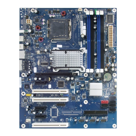
Intel Desktop Board DP35DP Technical Product Specification 1.1.2 Board Layout Figure 1 shows the location of the major components. Figure 1. Major Board Components Table 2 lists the components identified in Figure 1. -
Page 13: Board Components Shown In Figure 1
Front panel CIR receiver (input) header Main Power connector (2 X 12) Chassis intrusion header Battery Front chassis fan header Intel 82801IR I/O Controller Hub (ICH9R) BIOS Setup configuration jumper block Auxiliary front panel power LED header Front panel header Serial ATA connectors [5]... -
Page 14: Block Diagram
Intel Desktop Board DP35DP Technical Product Specification 1.1.3 Block Diagram Figure 2 is a block diagram of the major functional areas. Figure 2. Block Diagram... -
Page 15: Legacy Considerations
The board is designed to support the following processors: • Intel Core 2 Quad processor in an LGA775 socket with a 1066 MHz system bus • Intel Core 2 Duo processor in an LGA775 socket with a 1066 or 800 MHz system bus •... -
Page 16: System Memory
Intel Desktop Board DP35DP Technical Product Specification System Memory The board has four DIMM sockets and support the following memory features: • 1.8 V (only) DDR2 SDRAM DIMMs with gold-plated contacts • Unbuffered, single-sided or double-sided DIMMs with the following restriction: Double-sided DIMMS with x16 organization are not supported. -
Page 17: Memory Configurations
Product Description 1.5.1 Memory Configurations The Intel 82P35 MCH supports the following types of memory organization: • Dual channel (Interleaved) mode. This mode offers the highest throughput for real world applications. Dual channel mode is enabled when the installed memory capacities of both DIMM channels are equal. -
Page 18: Memory Channel And Dimm Configuration
Intel Desktop Board DP35DP Technical Product Specification Figure 3 illustrates the memory channel and DIMM configuration. NOTE The DIMM 0 sockets of both channels are blue. The DIMM 1 sockets of both channels are black. Figure 3. Memory Channel and DIMM Configuration INTEGRATOR’S NOTE... -
Page 19: Intel P35 Express Chipset
This Intel desktop board supports Intel Viiv™ processor technology. To be eligible for the Intel Viiv processor technology brand, a system must meet certain hardware and software requirements. To get the list of requirements for Intel Viiv processor technology branding as well as all the features supported by Intel Viiv processor technology, refer to http://www.intel.com/products/viiv/index.htm... -
Page 20: Serial Ata Interfaces
Intel Desktop Board DP35DP Technical Product Specification 1.6.3 Serial ATA Interfaces The board provides five Serial ATA (SATA) connectors, which support one device per connector. The board also provides one red-colored external Serial ATA (eSATA) connector. 1.6.3.1 Serial ATA Support The DP35DP Desktop Board’s Serial ATA controller offers six independent Serial ATA... -
Page 21: Parallel Ide Controller
Product Description Parallel IDE Controller The Parallel ATA IDE controller has one bus-mastering Parallel ATA IDE interface. The Parallel ATA IDE interface supports the following modes: • Programmed I/O (PIO): processor controls data transfer. • 8237-style DMA: DMA offloads the processor, supporting transfer rates of up to 16 MB/sec. -
Page 22: Legacy I/O Controller
The emitter header consists of two output ports which the PC can use to emulate “learned” infrared commands in order to control external electronic hardware. Customers are required to buy or create their own interface modules to plug into Intel Desktop Boards for this feature to work. These interface modules may be included in some boxed versions of DP35DP boards. -
Page 23: 1.10 Audio Subsystem
Back panel – Pink Back panel – Black Back panel - Orange 1.10.1 Audio Subsystem Software Audio software and drivers are available from Intel’s World Wide Web site. For information about Refer to Obtaining audio software and drivers Section 1.2, page 15... -
Page 24: Audio Connectors And Headers
Intel Desktop Board DP35DP Technical Product Specification 1.10.2 Audio Connectors and Headers The board contains audio connectors on the back panel and audio headers on the component side of the board. The front panel audio header provides mic in and line out signals for the front panel. -
Page 25: 1.11 Lan Subsystem
Refer to LAN software and drivers http://downloadcenter.intel.com ® 1.11.1 Intel 82566DC Gigabit Ethernet Controller The Intel 82566DC Gigabit Ethernet Controller supports the following features: • PCI Express link • 10/100/1000 IEEE 802.3 compliant • Compliant to IEEE 802.3x flow control support •... -
Page 26: Lan Subsystem Software
Intel Desktop Board DP35DP Technical Product Specification 1.11.2 LAN Subsystem Software LAN software and drivers are available from Intel’s World Wide Web site. For information about Refer to Obtaining LAN software and drivers Section 1.2, page 15 1.11.3 RJ-45 LAN Connector with Integrated LEDs Two LEDs are built into the RJ-45 LAN connector (shown in Figure 5 below). -
Page 27: 1.12 Hardware Management Subsystem
Chassis intrusion detection 1.12.1 Hardware Monitoring and Fan Control The features of the hardware monitoring and fan control include: • Intel Quiet System Technology, delivering acoustically-optimized thermal management • Fan speed control controllers and sensors integrated into the ICH9R •... -
Page 28: Thermal Monitoring
Intel Desktop Board DP35DP Technical Product Specification 1.12.4 Thermal Monitoring Figure 6 shows the locations of the thermal sensors and fan headers. Item Description Auxiliary rear chassis fan Rear chassis fan Thermal diode, located on processor die Thermal diode, located on the MCH die... -
Page 29: 1.13 Power Management
⎯ Wake from USB ⎯ Power Management Event signal (PME#) wake-up support ® ® ⎯ Intel Quick Resume Technology Drivers (Intel QRTD) (optional) ⎯ Wake from Consumer IR 1.13.1 ACPI ACPI gives the operating system direct control over the power management and Plug and Play functions of a computer. -
Page 30: Power States And Targeted System Power
Intel Desktop Board DP35DP Technical Product Specification 1.13.1.1 System States and Power States Under ACPI, the operating system directs all system and device power state transitions. The operating system puts devices in and out of low-power states based on user preferences and knowledge of how devices are being used by applications. -
Page 31: Wake-Up Devices And Events
1.13.1.2 ENERGY STAR* In 2007, the US Department of Energy and the US Environmental Protection Agency revised the ENERGY STAR* requirements. Intel has worked directly with these two governmental agencies to define the new requirements. Currently Intel Desktop Boards meet the new requirements. -
Page 32: Hardware Support
• PME# signal wake-up support • WAKE# signal wake-up support • Intel Quick Resume Technology Drivers (Intel QRTD) (optional) • Wake from Consumer IR LAN wake capabilities and Instantly Available PC technology require power from the +5 V standby line. -
Page 33: Fan Headers
Product Description 1.13.2.2 Fan Headers The function/operation of the fan headers is as follows: • The fans are on when the board is in the S0 state. • The fans are off when the board is off or in the S3, S4, or S5 state. •... -
Page 34: Instantly Available Pc Technology
Intel Desktop Board DP35DP Technical Product Specification 1.13.2.4 Instantly Available PC Technology CAUTION For Instantly Available PC technology, the +5 V standby line from the power supply must be capable of providing adequate +5 V standby current. Failure to provide adequate standby current when implementing Instantly Available PC technology can damage the power supply. -
Page 35: Location Of The Standby Power Indicator Led
Product Description 1.13.2.8 +5 V Standby Power Indicator LED The +5 V standby power indicator LED shows that power is still present even when the computer appears to be off. Figure 7 shows the location of the standby power indicator LED. CAUTION If AC power has been switched off and the standby power indicator is still lit, disconnect the power cord before installing or removing any devices connected to the... - Page 36 Intel Desktop Board DP35DP Technical Product Specification...
-
Page 37: Technical Reference
512 MB) • Memory-mapped I/O that is dynamically allocated for PCI Conventional and PCI Express add-in cards • Base graphics memory support (1 MB or 8 MB) • Intel Management Engine Interface single channel (8 MB) or dual channel (16 MB) -
Page 38: Detailed System Memory Address Map
Intel Desktop Board DP35DP Technical Product Specification The amount of installed memory that can be used will vary based on add-in cards and BIOS settings. Figure 8 shows a schematic of the system memory map. All installed system memory can be used when there is no overlap of system addresses. -
Page 39: System Memory Map
Technical Reference Table 9 lists the system memory map. Table 9. System Memory Map Address Range Address Range (decimal) (hex) Size Description 1024 K - 8388608 K 100000 - 1FFFFFFFF 8191 MB Extended memory 960 K - 1024 K F0000 - FFFFF 64 KB Runtime BIOS 896 K - 960 K... -
Page 40: Connectors And Headers
Intel Desktop Board DP35DP Technical Product Specification Connectors and Headers CAUTION Only the following connectors and headers have overcurrent protection: Back panel and front panel USB, with support for 1394. The other internal connectors/headers are not overcurrent protected and should connect only to devices inside the computer’s chassis, such as fans and internal... -
Page 41: Back Panel Connectors
Technical Reference 2.2.1 Back Panel Connectors Figure 9 shows the location of the back panel connectors. Item Description IEEE-1394a USB ports [2] USB ports [2] USB ports [2] Surround left/right channel audio out Center channel and LFE (subwoofer) audio out Audio line in S/PDIF Digital audio out (optical) Mic in... -
Page 42: Component-Side Connectors And Headers
Intel Desktop Board DP35DP Technical Product Specification 2.2.2 Component-side Connectors and Headers Figure 10 shows the locations of the component-side connectors and headers. Figure 10. Component-side Connectors and Headers... -
Page 43: Component-Side Connectors And Headers Shown In Figure 10
Technical Reference Table 10 lists the component-side connectors and headers identified in Figure 10. Table 10. Component-side Connectors and Headers Shown in Figure 10 Item/callout from Figure 10 Description PCI Conventional bus add-in card connector Auxiliary rear chassis fan header PCI Express x1 add-in card connector PCI Express x1 add-in card connector High Definition Audio Link header... -
Page 44: Hd Audio Link Header
Intel Desktop Board DP35DP Technical Product Specification 2.2.2.1 Signal Tables for the Connectors and Headers Table 11. HD Audio Link Header Signal Name Signal Name BCLK Ground RST# 3.3 VCC SYNC Ground 3.3 VCC SDI0 +12 V SDI1 Key (no pin) Aud RSVD 3.3 V STBY... -
Page 45: Chassis Intrusion Header
Technical Reference Table 15. Chassis Intrusion Header Signal Name Intruder Ground Table 16. Front and Rear Chassis (3-Pin) Fan Headers Signal Name Control +12 V Tach Table 17. Processor and Auxiliary Rear Chassis (4-Pin) Fan Headers Signal Name Ground +12 V FAN_TACH FAN_CONTROL Table 20. -
Page 46: Auxiliary Front Panel Power/Sleep Led Header
Intel Desktop Board DP35DP Technical Product Specification 2.2.2.2 Add-in Card Connectors The board has the following add-in card connectors: • PCI Express x16: one connector supporting simultaneous transfer speeds up to 4 GBytes/sec of peak bandwidth per direction and up to 8 GBytes/sec concurrent bandwidth •... -
Page 47: Processor Core Power Connector
Main power – a 2 x 12 connector. This connector is compatible with 2 x 10 connectors previously used on Intel Desktop boards. The board supports the use of ATX12V power supplies with either 2 x 10 or 2 x 12 main power cables. When... -
Page 48: Connection Diagram For Front Panel Header
Intel Desktop Board DP35DP Technical Product Specification 2.2.2.5 Front Panel Header This section describes the functions of the front panel header. Table 21 lists the signal names of the front panel header. Figure 11 is a connection diagram for the front panel header. -
Page 49: States For A One-Color Power Led
Technical Reference 2.2.2.5.1 Hard Drive Activity LED Header Pins 1 and 3 can be connected to an LED to provide a visual indicator that data is being read from or written to a hard drive. Proper LED function requires one of the following: •... -
Page 50: Connection Diagram For Front Panel Usb Headers
Intel Desktop Board DP35DP Technical Product Specification 2.2.2.6 Front Panel USB Headers Figure 12 is a connection diagram for the front panel USB headers. INTEGRATOR’S NOTES • The +5 V DC power on the USB headers is fused. • Use only a front panel USB connector that conforms to the USB 2.0 specification for high-speed USB devices. -
Page 51: Jumper Block
Technical Reference Jumper Block CAUTION Do not move the jumper with the power on. Always turn off the power and unplug the power cord from the computer before changing a jumper setting. Otherwise, the board could be damaged. Figure 14 shows the location of the jumper block. The jumper determines the BIOS Setup program’s mode. -
Page 52: Mechanical Considerations
Intel Desktop Board DP35DP Technical Product Specification Mechanical Considerations 2.4.1 Form Factor The board is designed to fit into an ATX-form-factor chassis. Figure 15 illustrates the mechanical form factor for the board. Dimensions are given in inches [millimeters]. The outer dimensions are 11.60 inches by 9.60 inches [294.64 millimeters by 243.84 millimeters]. -
Page 53: Electrical Considerations
10 A 0.3 A 3.0 A For information about Refer to Selecting an appropriate power supply http://support.intel.com/support/motherboards/desktop/sb/ CS-026472.htm 2.5.2 Fan Header Current Capability CAUTION The processor fan must be connected to the processor fan header, not to a chassis fan header. -
Page 54: Add-In Board Considerations
Failure to ensure appropriate airflow may result in reduced performance of both the processor and/or voltage regulator or, in some instances, damage to the board. For a list of chassis that have been tested with Intel desktop boards please refer to the following website: http://developer.intel.com/design/motherbd/cooling.htm... -
Page 55: Localized High Temperature Zones
Item Description Processor voltage regulator area Processor Intel 82P35 MCH Intel 82801IR (ICH9R) Figure 16. Localized High Temperature Zones Table 27 provides maximum case temperatures for the board components that are sensitive to thermal changes. The operating temperature, current load, or operating frequency could affect case temperatures. -
Page 56: Reliability
Intel Desktop Board DP35DP Technical Product Specification Reliability The Mean Time Between Failures (MTBF) prediction is calculated using component and subassembly random failure rates. The calculation is based on the Bellcore Reliability Prediction Procedure, TR-NWT-000332, Issue 4, September 1991. The MTBF prediction is used to estimate repair rates and spare parts requirements. -
Page 57: Overview Of Bios Features
3.10 BIOS Security Features ..............64 Introduction The board uses an Intel BIOS that is stored in the Serial Peripheral Interface Flash Memory (SPI Flash) and can be updated using a disk-based program. The SPI Flash contains the BIOS Setup program, POST, the PCI auto-configuration utility, LAN EEPROM information, and Plug and Play support. -
Page 58: Bios Flash Memory Organization
Intel Desktop Board DP35DP Technical Product Specification Table 29 lists the BIOS Setup program menu features. Table 29. BIOS Setup Program Menu Bar Maintenance Main Advanced Security Power Boot Exit Clears Displays Configures Sets Configures Selects boot Saves or passwords and... -
Page 59: Pci Ide Support
Overview of BIOS Features 3.3.2 PCI IDE Support If you select Auto in the BIOS Setup program, the BIOS automatically sets up the PCI IDE connector with independent I/O channel support. The IDE interface supports hard drives up to ATA-66/100/133 and recognizes any ATAPI compliant devices, including CD-ROM drives, tape drives, and Ultra DMA drives. -
Page 60: Legacy Usb Support
Legacy USB support from the BIOS is no longer used. 7. Additional USB legacy feature options can be access by using Intel Integrator Toolkit. To install an operating system that supports USB, verify that Legacy USB support in the BIOS Setup program is set to Enabled and follow the operating system’s... -
Page 61: Language Support
Integrator’s Toolkit that is available from Intel can be used to create a custom splash screen. NOTE If you add a custom splash screen, it will share space with the Intel branded logo. Refer to For information about Intel Integrator Toolkit http://developer.intel.com/design/motherbd/software/itk/... -
Page 62: Boot Options
Intel Desktop Board DP35DP Technical Product Specification Boot Options In the BIOS Setup program, the user can choose to boot from a diskette drive, hard drive, USB drive, USB flash drive, CD-ROM, or the network. The default setting is for the diskette drive to be the first boot device, the hard drive second, and the ATAPI CD-ROM third. -
Page 63: Adjusting Boot Speed
It is possible to optimize the boot process to the point where the system boots so quickly that the Intel logo screen (or a custom logo splash screen) will not be seen. Monitors and hard disk drives with minimum initialization times can also contribute to a boot time that might be so fast that necessary logo screens and POST messages cannot be seen. -
Page 64: 3.10 Bios Security Features
Intel Desktop Board DP35DP Technical Product Specification 3.10 BIOS Security Features The BIOS includes security features that restrict access to the BIOS Setup program and who can boot the computer. A supervisor password and a user password can be set for the BIOS Setup program and for booting the computer, with the following restrictions: •... -
Page 65: Error Messages And Beep Codes
Error Messages and Beep Codes What This Chapter Contains 4.1 Speaker ..................65 4.2 BIOS Beep Codes ................65 4.3 BIOS Error Messages ............... 65 4.4 Port 80h POST Codes ............... 66 Speaker The board-mounted speaker provides audible error code (beep code) information during POST. -
Page 66: Port 80H Post Codes
Intel Desktop Board DP35DP Technical Product Specification Port 80h POST Codes During the POST, the BIOS generates diagnostic progress codes (POST codes) to I/O port 80h. If the POST fails, execution stops and the last POST code generated is left at port 80h. -
Page 67: Port 80H Post Codes
Error Messages and Beep Codes Table 37. Port 80h POST Codes POST Code Description of POST Operation Host Processor Power-on initialization of the host processor (Boot Strap Processor) Host processor cache initialization (including APs) Starting Application processor initialization SMM initialization Chipset Initializing a chipset component Memory... - Page 68 Intel Desktop Board DP35DP Technical Product Specification Table 37. Port 80h POST Codes (continued) POST Code Description of POST Operation Keyboard (PS/2 or USB) Resetting keyboard Disabling keyboard Detecting presence of keyboard Enabling the keyboard Clearing keyboard input buffer Instructing keyboard controller to run Self Test (PS/2 only)
- Page 69 Error Messages and Beep Codes Table 37. Port 80h POST Codes (continued) POST Code Description of POST Operation DXE Drivers Waiting for user input Checking password Entering BIOS setup Calling Legacy Option ROMs Runtime Phase/EFI OS Boot Entering Sleep state Exiting Sleep state EFI boot service ExitBootServices ( ) has been called EFI runtime service SetVirtualAddressMap ( ) has been called...
-
Page 70: Typical Port 80H Post Sequence
Intel Desktop Board DP35DP Technical Product Specification Table 38. Typical Port 80h POST Sequence POST Code Description Initializing a chipset component Reading SPD from memory DIMMs Detecting presence of memory DIMMs Configuring memory Testing memory Loading recovery capsule Entered DXE phase... -
Page 71: Regulatory Compliance And Battery Disposal Information
Regulatory Compliance and Battery Disposal Information What This Chapter Contains 5.1 Regulatory Compliance..............71 5.2 Battery Disposal Information............. 81 Regulatory Compliance This section contains the following regulatory compliance information for Desktop Board DP35DP: • Safety standards • European Union Declaration of Conformity statement •... -
Page 72: European Union Declaration Of Conformity Statement
European Union Declaration of Conformity Statement ® We, Intel Corporation, declare under our sole responsibility that the product Intel Desktop Board DP35DP is in conformity with all applicable essential requirements necessary for CE marking, following the provisions of the European Council Directive 2004/108/EC (EMC Directive) and 2006/95/EC (Low Voltage Directive). - Page 73 Regulatory Compliance and Battery Disposal Information Polski Niniejszy produkt jest zgodny z postanowieniami Dyrektyw Unii Europejskiej 2004/108/EC i 73/23/EWG. Portuguese Este produto cumpre com as normas da Diretiva Européia 2004/108/EC & 2006/95/EC. Español Este producto cumple con las normas del Directivo Europeo 2004/108/EC & 2006/95/EC.
-
Page 74: Product Ecology Statements
恰当的重复使用处理。 请参考http://www.intel.com/intel/other/ehs/product_ecology 了解此计划的详情,包括涉及产品之范围、回收地点、运送指导、条款和条件等。 Deutsch Als Teil von Intels Engagement für den Umweltschutz hat das Unternehmen das Intel Produkt-Recyclingprogramm implementiert, das Einzelhandelskunden von Intel Markenprodukten ermöglicht, gebrauchte Produkte an ausgewählte Standorte für ordnungsgemäßes Recycling zurückzugeben. Details zu diesem Programm, einschließlich der darin eingeschlossenen Produkte, verfügbaren Standorte, Versandanweisungen, Bedingungen usw., finden Sie auf der... - Page 75 Regulatory Compliance and Battery Disposal Information Français Dans le cadre de son engagement pour la protection de l'environnement, Intel a mis en œuvre le programme Intel Product Recycling Program (Programme de recyclage des produits Intel) pour permettre aux consommateurs de produits Intel de recycler les produits usés en les retournant à...
-
Page 76: Lead Free Desktop Board
Intel Desktop Board DP35DP Technical Product Specification Türkçe Intel, çevre sorumluluğuna bağımlılığının bir parçası olarak, perakende tüketicilerin Intel markalı kullanılmış ürünlerini belirlenmiş merkezlere iade edip uygun şekilde geri dönüştürmesini amaçlayan Intel Ürünleri Geri Dönüşüm Programı’nı uygulamaya koymuştur. Bu programın ürün kapsamı, ürün iade merkezleri, nakliye talimatları, kayıtlar ve şartlar v.s dahil bütün ayrıntılarını... -
Page 77: Lead-Free Board Markings
Regulatory Compliance and Battery Disposal Information Table 40 shows the various forms of the “Lead-Free 2 Level Interconnect” mark as it appears on the board and accompanying collateral. Table 40. Lead-Free Board Markings Description Mark Lead-Free 2 Level Interconnect: This symbol is used to identify electrical and electronic assemblies and components in which the lead (Pb) concentration... -
Page 78: Emc Regulations
Intel Desktop Board DP35DP Technical Product Specification 5.1.4 EMC Regulations Desktop Board DP35DP complies with the EMC regulations stated in Table 41 when correctly installed in a compatible host system. Table 41. EMC Regulations Regulation Title FCC 47 CFR Part 15,... - Page 79 Regulatory Compliance and Battery Disposal Information Japanese Kanji statement translation: this is a Class B product based on the standard of the Voluntary Control Council for Interference from Information Technology Equipment (VCCI). If this is used near a radio or television receiver in a domestic environment, it may cause radio interference.
-
Page 80: Product Certification Markings (Board Level)
China RoHS/Environmentally Friendly Use Period Logo: This is an example of the symbol used on Intel Desktop Boards and associated collateral. The color of the mark may vary depending upon the application. The Environmental Friendly Usage Period (EFUP) for Intel Desktop Boards has... -
Page 81: Battery Disposal Information
Regulatory Compliance and Battery Disposal Information Battery Disposal Information CAUTION Risk of explosion if the battery is replaced with an incorrect type. Batteries should be recycled where possible. Disposal of used batteries must be in accordance with local environmental regulations. PRECAUTION Risque d'explosion si la pile usagée est remplacée par une pile de type incorrect. - Page 82 Intel Desktop Board DP35DP Technical Product Specification PRECAUCIÓN Existe peligro de explosión si la pila no se cambia de forma adecuada. Utilice solamente pilas iguales o del mismo tipo que las recomendadas por el fabricante del equipo. Para deshacerse de las pilas usadas, siga igualmente las instrucciones del fabricante.
- Page 83 Regulatory Compliance and Battery Disposal Information AWAS Risiko letupan wujud jika bateri digantikan dengan jenis yang tidak betul. Bateri sepatutnya dikitar semula jika boleh. Pelupusan bateri terpakai mestilah mematuhi peraturan alam sekitar tempatan. OSTRZEŻENIE Istnieje niebezpieczeństwo wybuchu w przypadku zastosowania niewłaściwego typu baterii.
- Page 84 Intel Desktop Board DP35DP Technical Product Specification...
Need help?
Do you have a question about the BOXDP35DPM and is the answer not in the manual?
Questions and answers