Table of Contents
Advertisement
Quick Links
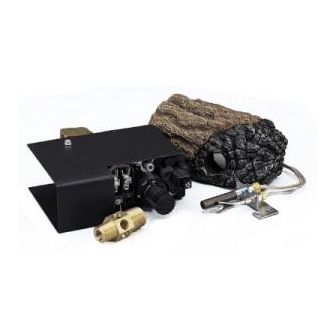
GA9150A REMOTE-READY VALVE/PILOT kit
WARNING: If the information in this manual is not
followed exactly, a fire or explosion may result causing
property damage, personal injury or loss of life.
Installation and service must be performed by a quali-
fied installer, service agency or the gas supplier.
WARNING: Improper installation, adjustment, al-
teration, service or maintenance can cause injury or
property damage. Refer to this manual for correct in-
stallation and operational procedures. For assistance
or additional information consult a qualified installer,
service agency or the gas supplier.
INSTALLER: Leave this manual with the appliance.
CONSUMER: Retain this manual for future reference.
The GA9150A Series Remote Ready On/Off Safety Valve/Pilot kit contains the following:
• Piezo Ignitor
• MV Valve
• Propane/LP Conversion Regulator 106380-01
• Pilot Burner
(with natural gas orifice)
• Piezo Ignitor Electrode
• Steel Shroud - Pilot Kit
• Piezo Ignitor Cover
• Natural Gas Brass Orifice
• Natural Gas Brass Orifice
• Natural Gas Brass Orifice
INSTRUCTION MANUAL
For All Single, Dual and Triple Burner
Natural and Propane/LP Gas Logs
097159-04
14512
901073-01
901072-01
106823-01
106824-01
901064-03
901064-04
901064-09
Save this manual for future reference.
For more information, visit www.desatech.com
• Brass Flare Adaptor Fitting
• Propane/LP Conversion Decal
• Screw #10-32 x 1/4"
• 18" Propane/LP Brass Orifice
• 24" Propane/LP Brass Orifice
• 30" Propane/LP Brass Orifice
• Propane/LP Brass Air Mixer
• Propane/LP Pilot Burner Orifice
• Screws 1/4" #8 "B" pt (6 ea.)
• Refractory Remote Control
• 4" Jumper Wire
901056-01
901691-01
11107
901065-02
901065-03
901065-04
901066-02
901070-01
901075-01
901837-01
14580
Advertisement
Table of Contents

Related Manuals for Desa GA9150A


Summary of Contents for Desa GA9150A
- Page 1 GA9150A REMOTE-READY VALVE/PILOT kit INSTRUCTION MANUAL For All Single, Dual and Triple Burner Natural and Propane/LP Gas Logs WARNING: If the information in this manual is not followed exactly, a fire or explosion may result causing property damage, personal injury or loss of life. Installation and service must be performed by a quali- fied installer, service agency or the gas supplier.
-
Page 2: Installation
INSTALLATION Btu/Hr Input Btu/Hr Input Minimum MODEL DESCRIPTION Natural Gas Propane Gas Vent Opening CVSR18 18" Single Burner 50,000 40,000 8" dia. CPVSR18 18" Single Burner 50,000 40,000 8" dia. CVSR24 24" Single Burner 60,000 50,000 8" dia. CPVSR24 24" Single Burner 60,000 50,000 8"... - Page 3 INSTALLATION Installation must include an equipment shutoff valve, union and plugged 1/8" NPT tap. Locate Continued NPT tap within reach for test gauge hook up. Installation Items Needed NPT tap must be upstream from log set (see Before installing log set, make sure you have Figure 3, page 4).
-
Page 4: Checking Gas Connections
INSTALLATION PRESSURE TESTING GAS SUPPLY PIPING SYSTEM Continued Test Pressures In Excess Of 1/2 PSIG Approved Flexible (3.5 kPa) Natural Gas Gas Hose (if allowed 1. Disconnect log set and its individual From Gas Meter by local codes) (5" W.C.** to 10.5" equipment shutoff valve from gas supply W.C. - Page 5 INSTALLATION 6. Install the inlet fitting into the inlet opening of the gas control valve (see Figure 9). Use Continued thread sealant on the male pipe threads. Equipment 7. Place the burner pan assembly in the Shutoff Valve center of the fireplace floor. Make sure the front of pan faces forward.
- Page 6 INSTALLATION PROPANE/LP GAS CONVERSION Continued To convert to propane/LP gas, the regulator pres- sure must be reset also the burner inlet fitting 8. Thread the gas supply adaptor to the and pilot orifice must be replaced. The propane/ fireplace gas supply pipe. Adjust to most LP burner inlet fitting is supplied with the orifice convenient position.
- Page 7 INSTALLATION Mounting Screws Continued GAS CONTROL VALVE CONVERSION Convert the gas control valve by changing out the valve regulator portion of the gas valve. 1. Using a TORX T20 or slotted screwdriver, re- move and discard the three mounting screws, pressure regulator tower and diaphragm/ spring components (see Figure 13).
-
Page 8: Operation
INSTALLATION OPERATION Continued FOR yOUR SAFETy REMOTE CONTROL OPTION REAd BEFORE LIGHTING HRC100 WARNING: If you do not fol- If you are using the HRC100 remote control low these instructions exactly, option, you must first connect the leads of the receiver to the terminal block on the gas a fire or explosion may result control (see Figure 16). -
Page 9: To Turn Off Gas To Appliance
OPERATION Ignitor Continued Button 4. Press in and turn control knob clockwise Control to the OFF position. Knob 5. Wait five (5) minutes to clear out any gas. Then smell for gas, including near the floor. If you smell gas, STOP! Follow “B” in the safety information. -
Page 10: Optional Remote Operation
OPERATION Continued OPTIONAL REMOTE OPERATION Note: All remote control accessories must be purchased separately. Follow instructions included with the remote control. NOTICE: you must light the pilot before using the hand-held re- mote control unit. See Lighting Instructions, page 8. After lighting, let pilot flame burn for about one minute. - Page 11 NOTES _____________________________________________________ ______________________________________________________ ______________________________________________________ ______________________________________________________ ______________________________________________________ ______________________________________________________ ______________________________________________________ ______________________________________________________ ______________________________________________________ ______________________________________________________ ______________________________________________________ ______________________________________________________ ______________________________________________________ _____________________________________________________ ______________________________________________________ ______________________________________________________ ______________________________________________________ ______________________________________________________ ______________________________________________________ ______________________________________________________ ______________________________________________________ ______________________________________________________ ______________________________________________________ ______________________________________________________ ______________________________________________________ ______________________________________________________ _____________________________________________________ ______________________________________________________ ______________________________________________________ ______________________________________________________ ______________________________________________________ ______________________________________________________ ______________________________________________________ ______________________________________________________ ______________________________________________________ 901053-01J www.desatech.com...
-
Page 12: Warranty
WARRANTY KEEP THIS WARRANTY Model (located on product or identification tag) _____________________________ Serial No. (located on product or identification tag) __________________________ Date Purchased __________________________ Keep receipt for warranty verification. DESA HEATING, LLC LIMITED WARRANTIES New Products Standard Warranty: DESA Heating, LLC warrants this new product and any parts thereof to be free from defects in material and workmanship for a period of one (1) year from the date of first purchase from an authorized dealer provided the product has been installed, maintained and operated in accordance with DESA Heating, LLC’s warnings and instructions.
Need help?
Do you have a question about the GA9150A and is the answer not in the manual?
Questions and answers