Table of Contents
Advertisement
Quick Links
Precaution
DANGER! Caution! Electric Shock!
1.
Do not touch the AC terminals while the power is supplied to the controller to prevent an electric shock.
2.
Make sure power is disconnected while checking the unit inside.
WARNING!
This controller is an open-type temperature controller. Make sure to evaluate any dangerous application in which a
serious human injury or serious property damage may occur.
1.
Always use recommended solder-less terminals: Fork terminal with isolation. (M3 screw, width is 6.0mm)
2.
Do not allow dust or foreign objects to fall inside the controller to prevent it from malfunctioning.
3.
Never modify or disassemble the controller.
4.
Do not connect anything to the "No used" terminals.
5.
Make sure all wires are connected to the correct polarity of terminals.
6.
Do not install and/or use the controller in places subject to:
Dust or corrosive gases and liquid
Vibration and shock
7.
Must turn power off when wiring and changing a temperature sensor.
8.
Be sure to use compensating wires that match the thermocouple types when extending or connecting the thermocouple wires.
9.
Please use wires with resistance when extending or connecting a platinum resistance thermometer (RTD).
10. Please keep the wire as short as possible when wiring a platinum resistance thermometer (RTD) to the controller and please
route power wires as far as possible from load wires to prevent interference and induced noise.
11. This controller is an open-type unit and must be placed in an enclosure away from high temperature, humidity, dripping water,
corrosive materials, airborne dust and electric shock or vibration.
12. Please make sure power cables and signals from instruments are all installed properly before energizing the controller,
otherwise serious damage may occur.
13. Please do not touch the terminals in the controller or try to repair the controller when power is applied to prevent an electric
shock.
14. Wait at least one minute after power is disconnected to allow capacitors to discharge, and please do not touch any internal
circuit within this period.
15. Do not use acid or alkaline liquids for cleaning. Please use a soft, dry cloth to clean the controller.
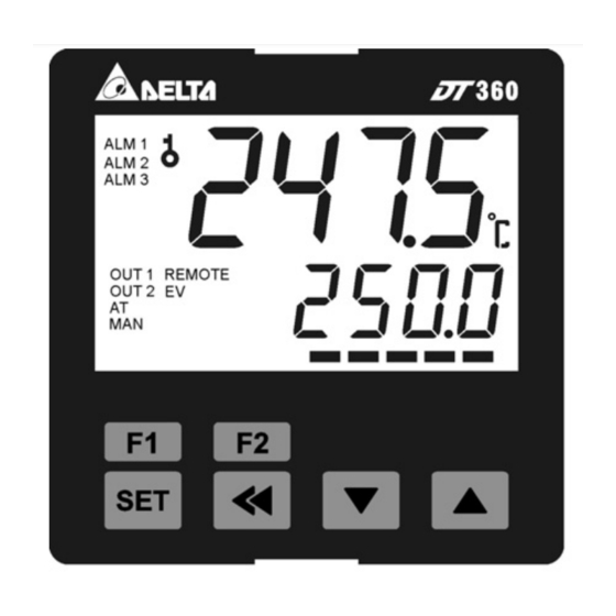
Display, LED & Pushbuttons
Odering Information
DT3 Series
Panel Size (W×H)
1st output group selection
Power supply
2nd output group selection
DT3 Series Temperature Controller Instruction Sheet
High humidity and high radiation
High voltage and high frequency
DT3: Delta 3 Series Temperature Controller
20: 4848 1/16 DIN W48 × H48mm
30: 7272 W72 × H72mm
R: Relay Output, 250 VAC, 5A
V: Voltage Pulse Output, 12V ±10%
C: DC Current Output, 4 ~ 20 mA
L: Linear Voltage Ouptut 0 ~ 10 VDC
A: AC 80 ~ 260 V
D: DC 24 VDC
0: None
R: Relay Outupt,250 VAC, 5A
40: 4896 1/8 DIN W48 × H96mm
60: 9696 1/4 DIN W96 × H96mm
1
Advertisement
Table of Contents

Related Manuals for Delta DT3 Series


Summary of Contents for Delta DT3 Series
- Page 1 15. Do not use acid or alkaline liquids for cleaning. Please use a soft, dry cloth to clean the controller. Display, LED & Pushbuttons Odering Information DT3 Series DT3: Delta 3 Series Temperature Controller 20: 4848 1/16 DIN W48 × H48mm 40: 4896 1/8 DIN W48 × H96mm Panel Size (W×H) 30: 7272 W72 ×...
- Page 2 V: Voltage Pulse Output, 12V ±10% C: DC Current Output 4 ~ 20 m A L: Linear Voltage Ouptut 0 ~ 10 VDC 0: None, 1: Event Input3, 2: RS-485 Communication EVENT inputs/ CT function (optional) 1 0: None, 1: Event Input2, 2: CT measure input2, 3: Retransmission Output EVENT inputs/ CT function (optional) 2 0: None, 1: Event Input1, 2: CT measure input1, 3: Remote Setpoint input EVENT inputs/ CT function (optional) 3...
- Page 3 ALARM1 LOW: Lower limit alarm 1 (display according to the setting in ALARM mode) ALARM2 HIGH: Upper limit alarm 2 (display according to the setting in ALARM mode) ALARM2 LOW: Lower limit alarm 2 (display according to the setting in ALARM mode) ALARM3 HIGH: Upper limit alarm 3 (set OUT2 to ALARM mode and it will display according to the setting in ALARM mode) ALARM3 LOW: Lower limit alarm 3 (set OUT2 to ALARM mode and it will display according to the...
- Page 4 ALARM mode) ALARM3 DELAY: Set up Alarm 3 delay (refer to “Alarm Outputs” ) (display when OUT2 is set to ALARM mode) PV Color Change Function: Select the alarm to change PV display color. (refer to "Alarm Outputs") OUT INVERT: Set up reverse alarm output (the last digit on the right indicates: OUT1 reverse; the 2nd last digit on the right indicates: OUT2 reverse) REMOTE TYPE: Set up Remote type (display when is set to REMO mode)
- Page 5 SV SLOPE: Set up rising slope (when CRTS = SLOP) ANALOG OUT1 MAX.: Adjust upper limit compensation for analog Output 1 (1scale = 1μA; 1scale = 1mV) ANALOG OUT1 MIN.: Adjust lower limit compensation for analog Output 1* (1 scale = 1μA; 1scale = 1mV) ANALOG OUT2 MAX.: Adjust upper limit compensation for analog Output 2* (1scale = 1μA;...
-
Page 6: Initial Start-Up Setting
Initial Start-up Setting When setting up DT3 for the first time, press key for more than 3 seconds till the screen display and select according to your temperature sensor type. Please be aware that a selection of wrong model would cause PV temperature display error. (Refer to the chart below) When setting up the temperature sensor type by using RS-485, write your value (range 0~19) into register 1004H. -
Page 7: Disable The Cold Junction Function
For example: Measure Value=25.0; Compensation = 1.2. After applying to the Compensation equation PV=26.2. Linear Compensation Gain (setting range = 0~0.999). Linear Compensation Gain Calculation equation: PV = Measure Value* (1 + Gain/1.000) + Compensation. For example: Measure Value=25.0; Gain= 0.100. After applying to the Gain calculation equation PV= 25.0 * (1 + 0.100 / 1.000) = 27.5。... - Page 8 To set Retransmission to positive/negative slopes (a Retransmission board must be installed first): In 【Initial Setting Mode】 set parameter, the last digit (Y) of xxxY indicates when Y=0 positive slope; when Y=1 negative slope. To adjust the lower limit of Retransmission: a、...
- Page 9 Output of when in PID control mode (Ctrl=PID): Heating Cooling Heating Cooling Set Point Set Point When the controller is in PID control and dual loop output mode, sets the P value of the 2nd set of PID. The 1st set of PID is generated when TUNE= AT, but user can also manually sets the PID value.
- Page 10 If the setting control is in running mode, the program will start running from the initial pattern and initial step, and carry out commands one by one. When the setting control is in end mode, the program will stop running and give out an output disable. When setting control is in stop control and temperature is controlled at the setting value before the stop, by re-selecting the start status, the program will start running from the initial pattern and initial step.
- Page 11 Remote compensation adjustment: input corresponding lower limit of analog signal at the Remote end, set Remote compensation adjustment by parameter in【Regulation Mode】 Remote gain adjustment: input corresponding upper limit of analog signal at the Remote end, set Remote compensation adjustment by parameter in【Regulation Mode】...
- Page 12 c、 Coef and DeadBand are added in the PID parameter for double output (one for heating and one for cooling). Coef refers to the ratio between the first and second portions of output (P parameter of second group =Coef*P, Coef= 0.01~99.99); DeadBand is the overlapping temperature of the P output of the first group and the second group.
- Page 13 Auto Fine-tune the PID value. During the calculation, AT LED lights up in the display panel. When the PV value generates 2 curves of temperature oscillation based on the SV value, the AT process is completed and the AT LED in the panel goes out. The calculated PID parameters are displayed in , of which their content can be revised by the user.
- Page 14 EVENT Function This controller provides a maximum of 3 EVENTs (EV1~EV3) for respectively setting EV functions as shown in the following Table <1>. For example, if EV1 is used for Run/Stop selection, when the controller is set to RUN status, if terminals in the Option1 slot are open, the controller is in RUN status;...
- Page 15 M203 M303 M103 M204 M304 M104 M205 M305 M105 M206 M306 M106 M207 M307 M107 M208 M308 M108 M209 M309 M109 M210 M310 M110 M211 M311 M111 M212 M312 M112 M213 M313 M113 M214 M314 M114 M215 M315 M115 M216 M316 M116 M217...
- Page 16 screen . If the password is incorrect, the screen will return to PV/SV display mode. Enter the new password two times in the screen. The screen will return to PV/SV display mode with the keys unlocked. If the two entries of password are not the same, the screen will go back to the state of step 2. Cannot remember the password: Restore factory settings to release the locking.
- Page 17 When HOLD status happens to PID program control, alarm output is ON. When STOP status happens to PID program control, alarm output is ON. When END status happens to PID program control, alarm output is ON. To set Alarm Mode: Use the parameters in 【Initial Setting Mode】...
- Page 18 1006H Heating/Cooling control selection Refer to Ouputput Mode Selection 1007H 1st group of Heating/Cooling 1~990, unit is 0.1 second. When the output setting = realy, the minimum control control cycle cycle is 5 second 1008H 2nd group of Heating/Cooling 1~990, unit is 0.1 second. When the output setting = realy, the minimum control control cycle cycle is 5 second 1~990 1009H...
- Page 19 1103H Reverse Output Bit1: output 2, Bit0: output 1 1104H Slope of Temperature Increase Unit: 0.1 / ℃ min or 0.1℃/sec (refer to CommunicationAddress 1124H) 1105H Remote Input Type Selection 0: 0~20m A , 1: 4~20m A, 2: 0~5V, 3: 1~5V, 4: 0~10V 1106H AT Control 0: AT(Auto-tune), 1: ST(Self-tune)
- Page 20 selection 0: No decimal place 1: decimal place. (Except for the thermocouple B,S,R type, 0812H Decimal point position selection all other thermocouple type are valid.) 0813H AT setting OFF: 0 (default), ON : 1 0814H Control RUN/STOP setting 0: STOP, 1: RUN (default) STOP setting for PID program 0815H 0: RUN (default), 1: STOP...
- Page 21 Panel Cutout Pattern Panel Cutout ( W * H ) Model Panel Cutout ( W * H ) 4848 (DT320) 45mm * 45mm 7272 (DT330) 68mm * 68mm 4896 (DT340) 44.5mm * 91.5mm 9696 (DT360) 91mm * 91mm...
Need help?
Do you have a question about the DT3 Series and is the answer not in the manual?
Questions and answers