Table of Contents
Advertisement
Quick Links
Advertisement
Table of Contents

Related Manuals for CDA HCE340


Summary of Contents for CDA HCE340
-
Page 1: Electric Hob
Manual for Installation, Use and Maintenance Passionate about style Customer Care Department • The Group Ltd. • Harby Road • Langar • Nottinghamshire • NG13 9HY T : 01949 862 012 F : 01949 862 003 E : service@cda.eu W : www.cda.eu... -
Page 2: Important Precautions And Recommendations
ENGLISH Instructions for use Dear Customer, Thank you for having purchased and given your preference to our product. The safety precautions and recommendations reported below are for your own safety and that of others. They will also provide a means by which to make full use of the features offered by your appliance. Please preserve this booklet carefully. - Page 3 FEATURES “2 GAS” COOKING HOB (Fig. 1.1) The appliance has class 3 COOKING POINTS 1. Semirapid burner (SR) - 1,75 kW 2. Rapid burner (R) - 3,00 kW CONTROL PANEL DESCRIPTION 3. Burner 2 (R) control knob 4. Burner 1 (SR) control knob 5.
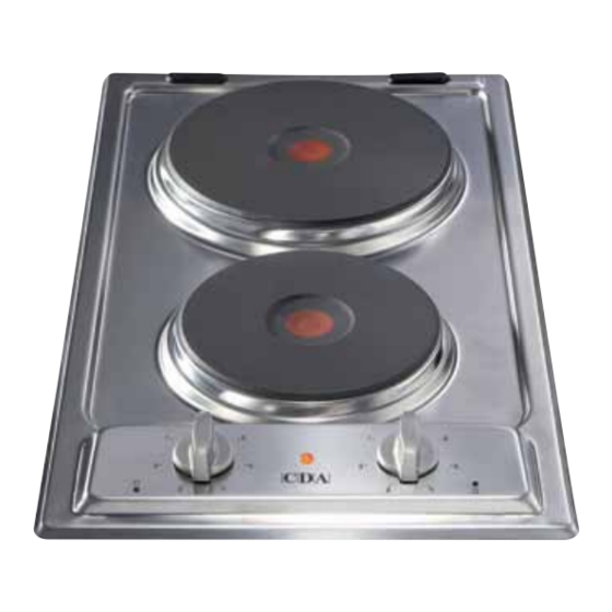
- Page 4 “2 ELECTRIC” COOKING HOB (Fig. 1.3) - Electrical isulation Class I. - Overheating surfaces protection Type Y. COOKING POINTS 1. Electrical plate Ø 145 - (1000 W - 1500 W) 2. Electrical plate Ø 180 - (1500 W - 2000 W) CONTROL PANEL DESCRIPTION 3.
-
Page 5: Gas Burners
GAS COOKING HOBS GAS BURNERS Gas flow to the burners is adjusted by turning the knobs (illustrated in figs. 2.1a - 2.1b) which control the safety valves. Turning the knob so that the indicator line points to the symbols printed on the panel achieves the following functions: full circle = closed valve... -
Page 6: Choice Of Burner
CHOICE OF BURNER DIAMETERS OF PANS WHICH MAY BE USED (fig. 2.4) ON THE HOBS The symbols printed on the panel beside the gas knobs indicate the correspondence between the knob and the burner. BURNERS MINIMUM MAX. The most suitable burner is to be chosen according to the diameter and volume capa- Semirapid 12 cm 22 cm... - Page 7 ELECTRIC COOKING HOBS NORMAL HOTPLATE To turn on the electric hotplate, rotate the knob (fig. 3.1 - 3.2) o the desired setting. The numbers from 1 to 6 or 1 to 12 indicate the operating positions with increasing number corresponding to higher temperature settings. When the pan comes to the boil, turn the heat down to the level desired.
- Page 8 VITROCERAMIC HOBS The main characteristic of this pyroceram cooker top is that it permits rapid vertical transmission of the heat from the heating elements below to the saucepans on top. The heat does not spread horizontally, however, and therefore the glass stays cold only a few centimetres from the hob.
- Page 9 HINTS FOR SAFE USE OF THE HOBS Hob controlled by Hob controlled by 7-position continuous energy switch regulation switch – Before switching on, check which knob controls the required hob. You are advised to 0 - 6 0 - 12 place the saucepan on the hob before switching on and to take it off after switching off.
-
Page 10: Cleaning And Maintenance
CLEANING AND MAINTENANCE GENERAL RECOMANDATION VITROCERAMIC HOB Before you begin cleaning you must ensure that the hob Before cleaning the top, make sure that it is is switched off. switched off. It is advisable to clean when the appliance is cold and espe- cially when cleaning the enamelled parts. - Page 11 BURNERS AND GRIDS These parts can be removed and cleaned with appropriate products. After cleaning, the burners and their flame distributors must be well dried and cor- rectly replaced. It is very important to check that the burner flame distributor and the cap has been correctly positioned - failure to do so can cause serious problems.
-
Page 12: Installation
Installation advice INSTALLATION IMPORTANT The appliance must be housed in heat-resistant units. – The appliance should be installed, regulated and adapted to function with other types of gas by a QUALIFIED INSTAL- These tops are designed to be embedded into kitchen LATION TECHNICIAN. - Page 13 WITH CUPBOARD DOORS (fig. 6.3) Fig. 6.3 The fixture has to be made according to specific requirements in order to prevent the gas burners from going out, even when the flame is turned down to minimum, due to pressure changes while opening or closing the cupboard doors. It is recommended that a 30 mm clearance be left between the cooker top and the fix- ture surface beneath it.
- Page 14 ELECTRICAL PLATES AND VITROCERAMIC COOKING HOBS Fig. 6.8b Fig. 6.8a TECHNICAL INFORMATION FOR THE INSTALLER Before installing the cooktop, remove the protective film. These cooking hobs are designed to be embedded into kitchen fixtures measuring 600 mm in depth and from 20 to 40 mm thick, for 2 electrical plates hob, and from 30 to 40 mm thick for vitroceramic hob.
- Page 15 FASTENING THE COOKTOP Each cooker top is provided with an installation kit including brackets and screws for fastening the top to fixture panels from 20-30 to 40 mm thick, figs. 6.11 (2 electrical plates hob) e 6.12 (vitroceramic hob). Cut the unit. Stretch gasket “D”...
-
Page 16: Gas Section
GAS SECTION GAS CONNECTIONS Make sure that the hob is adapted to function with the type of gas supply available (see label). If not, refer to the section headed “Adapting the appliance to function with diffe- rent types of gas”. GASES 1/2”... -
Page 17: Injectors Table
INJECTORS TABLE NOMINAL G30/G31 REDUCED Cat: 2H3+ POWER 28-30/37 mbar 20 mbar POWER Ø injector Ø injector BURNERS [Hs - kW] [Hs - kW] [1/100 mm] [1/100 mm] Semi-rapid (SR) 1,75 0,45 Rapid (R) 3,00 0,75 Triple ring (TR) 3,50 1,50 OPERATIONS TO BE PERFORMED WHEN SUBSTITUTING THE INJECTORS... -
Page 18: Electrical Section
ELECTRICAL SECTION A double pole switch must be provided no further than 2 metres IMPORTANT: Installation has to be carried out according from the appliance to the electrical supply. to the instructions provided by the manufacturer. Incorrect installation might cause harm and damage to If you are using the hob for the first time, or after a period of dis- people, animals or objects, for which the manufacturer use, you should set the controls to position 1 for approximately... - Page 19 REPAIRS REPLACING THE POWER SUPPLY CABLE (for 2 electrical plates and vitroceramic models) Turn the cooktop over and unhook the terminal board cover by inserting a screwdriver into the two hooks “A” (fig. 8.1). Open the cable gland by unscrewing screw “F” (fig. 8.2), unscrew the terminal screws and remove the cable.
-
Page 20: Ligação À Rede Eléctrica
PARTE ELÉCTRICA REPARAÇÕES Importante: A instalação deve ser efetuada conforme as instruções do fabricante. SUBSTITUIÇÃO DO CABO DE ALIMENTAÇÃO (mod. Uma instalação erronea pode causar danos às pessoas, placas eléctricas e placas vitroceramica) animais ou coisas e defronte a tais acontecimentos o fabricante não pode ser considerado responsável. - Page 21 Cod. 1103055 ß1 STRUZIONI PER L’USO • INSTRUCTIONS FOR USE • MODE D’EMPLOI • INSTRUCCIONES PA O • MANUAL DE USO • ISTRUZIONI PER L’USO • INSTRUCTIONS FOR USE • MODE D’EMP TRUCCIONES PARA EL USO • MANUAL DE USO • ISTRUZIONI PER L’USO • INSTRUCTION E •...
Need help?
Do you have a question about the HCE340 and is the answer not in the manual?
Questions and answers