Fire-Lite MS-9050UD Wiring Diagram
With keltron rcvr/xmtr
Hide thumbs
Also See for MS-9050UD:
- Manual (220 pages) ,
- Operating instructions (1 page) ,
- User manual (216 pages)
Advertisement
Quick Links
Keltron 95M3158 TTM-RPS
1. Terminals 7 and 8: Remote station alarm/trouble inputs.
2. Terminals 9 and 10: Sprinkler supervisory input.
TB5
TB6
TRBL
ALARM
For reasons of wiring diagram clarity, terminal designations
of Keltron modules are not shown in actual order. Follow
Keltron manual and module markings for exact terminal
locations to prevent severe module damage!
7
KELTRON
8
95M3158
TTM-RPS
9
UL 864
10
8th Edition only
RP-3.3K
R1
R2
3.3K
3.3K
0.5w
0.5w
Sprinkler Supervisory Signal
TB7
SUPV
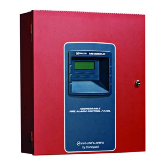
MS-9050UD Control Panel
(terminal blocks not shown in actual positions)
Document 52665 Rev A September 7, 2005
CAUTION!
TIP
TIP
1
RING
TELEPHONE LINE
RING
2
EARTH
EARTH
3
4
5
6
Alarm/Trouble Signal
4XTMF
4XTMF Module
Note: Cut TBL jumper on 4XTMF/4XTM
module to send alarm/trouble signal from
the same pair of terminals.
MS-9050UD
with Keltron RCVR/XMTR
Wiring Diagram
52665 Revision A
September 7, 2005
1
2
7
KELTRON*
3
95M3083
8
TRM-RP
9
4
UL 864
10
5
8th Edition only
6
* Note: For more information,
refer to Keltron manual.
TB3
ECN 05-345
TO CENTRAL
STATION
*
TO
POWER
SUPPY
Advertisement


Need help?
Do you have a question about the MS-9050UD and is the answer not in the manual?
Questions and answers