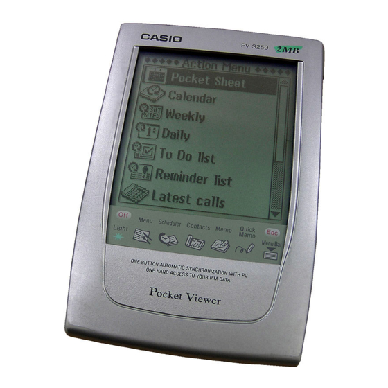
Casio PV-S250 User Manual
11. data communication
Hide thumbs
Also See for PV-S250:
- User manual (37 pages) ,
- Read this first manual (13 pages) ,
- User manual (12 pages)
Table of Contents
Advertisement
Quick Links
Download this manual
See also:
User Manual
Chapter
11
Data Communication
Data communications capabilities let you transfer data between two CASIO PV
Units, between a PV Unit and a BN-10/BN-20 Unit, or between a PV Unit and a
BN-10A/BN-20A/BN-40A Unit. You can also receive data from a CASIO SF,
CSF, or NX Series Unit, and communicate with a personal computer using PC
sync for Windows.
•
See the manual that comes with PC sync for Windows for details on connecting
to a computer and setting up for communication.
Using the Cradle
The PV Unit comes with a cradle that helps to make data communications quicker
and easier. The following procedures describe how to attach the PV Unit to and
detach it from the cradle.
To connect the PV Unit to the cradle
1. Turn off PV Unit power.
2. Place the PV Unit onto the cradle.
•
Gently but firmly press down on the PV Unit to ensure that it is inserted
into the cradle as far as it will go.
11
127
Advertisement
Table of Contents

Related Manuals for Casio PV-S250


Summary of Contents for Casio PV-S250
-
Page 1: Data Communication
Chapter Data Communication Data communications capabilities let you transfer data between two CASIO PV Units, between a PV Unit and a BN-10/BN-20 Unit, or between a PV Unit and a BN-10A/BN-20A/BN-40A Unit. You can also receive data from a CASIO SF, CSF, or NX Series Unit, and communicate with a personal computer using PC sync for Windows. - Page 2 To detach the PV Unit from the cradle 1. Turn off PV Unit power. 2. Angle the PV Unit forward as shown in the illustration, and then lift it straight up.
-
Page 3: Data Communications Between Two Pv Units
Chapter 11 Data Communication Data Communications Between Two PV Units This section describes how to set up and communicate between two PV Units. To connect two PV Units 1. Make sure that the power of both units is turned off. 2. - Page 4 3. Tap the Menu Bar icon to display the menu bar, and then tap System – Data communication. 4. Tap the button next to Pocket Viewer to specify the data communication configuration. 5. Tap the button next to Send. 6. Tap Set. 7.
-
Page 5: To Receive Data From The Terminal Unit On The Host Unit
Chapter 11 Data Communication To receive data from the terminal unit on the host unit 1. Perform steps 1 through 4 under “To send data from the host unit to the terminal unit”. 2. Tap the button next to Receive. 3. -
Page 6: Data Communications Between A Pv Unit And A Bn Unit
Notes • The above procedures can be used to send or receive all data in specific modes only. You cannot send or receive individual data items. • Data communication can be interrupted at any time by pressing Esc. This causes the message Stopped! to appear on the displays of both units. -
Page 7: To Send Data From The Pv Unit To The Bn Unit
Chapter 11 Data Communication 4. Use an optional SB-90 9-9 pin connector to connect the PV Unit cradle to the BN Unit Mini Cradle. Host unit (PV Unit) Terminal unit (BN Unit) Cradle Mini Cradle START button SB-90 9-9 pin connector •... - Page 8 4. Tap the button next to BUSINESS NAVIGATOR to specify the data communication configuration. 5. Tap the button next to Send. 6. Tap Set. 7. Tap the check boxes to specify the data you want to send (checked) and the data you do not want to send (unchecked). 8.
-
Page 9: To Receive Data From The Bn Unit On The Pv Unit
Chapter 11 Data Communication To receive data from the BN Unit on the PV Unit 1. Perform steps 1 through 4 under “To send data from the PV Unit to the BN Unit”. 2. Tap the button next to Receive. 3. -
Page 10: Receiving Data From An Sf/Csf/Nx Series Unit
• Transferring data from the PV-S250/PV-S450 to the BN Unit causes all euro symbols to be replaced by spaces. • The following shows the relationship between data when received by the PV Unit from a BN Unit. Mode BN Unit PV Unit Contacts PERSONAL... - Page 11 Chapter 11 Data Communication 4. Use an optional SB-90 9-9 pin connector to connect the PV Unit cradle to the other unit’s cable. PV Unit SF/CSF/NX Series Unit Cradle SB-90 3-9 pin cable SB-90 9-9 pin connector To make communication parameter settings 1.
-
Page 12: To Receive Data From An Sf/Csf/Nx Series Unit
6. Tap the buttons under Parity, Bit length, and BPS to make the settings you want. • Note that the settings you make here must match those of the connected SF/CSF/NX Series Unit. Otherwise, proper data communication will be impossible. 7. - Page 13 • Data cannot be received from the following CASIO units: SF-A Series, SF-5580, 5780, 5980, 5580E, 5780E, 5980E, 5590SY, 5790SY, 5990SY, 5590SYE, 5790SYE, 5990SYE, 6500SY, 6700SY, 6900SY, 7100SY, 7200SY.
Need help?
Do you have a question about the PV-S250 and is the answer not in the manual?
Questions and answers