Table of Contents
Advertisement
Quick Links
INSTALLATION GUIDE
ALARM AND REMOTE STARTER MODEL DELUXE 62
CONTENTS
System Features .......................................
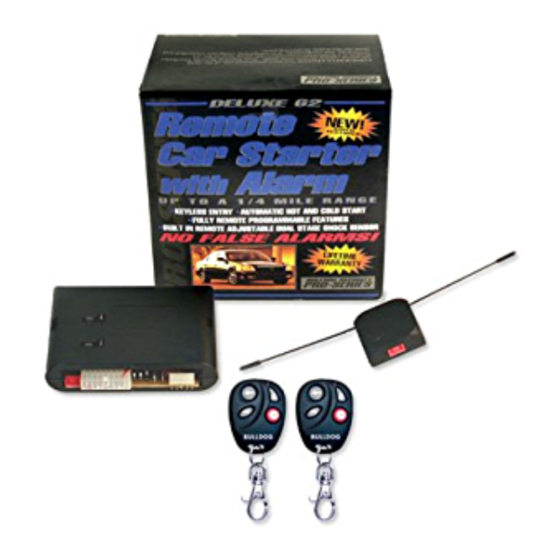
System Components .....................................
Tools Required ........................................
Technical Assistance ..................................
Before You Begin ......................................
Precautions ...........................................
Locating & Making Connections ........................ 4-7
Neutral Safety Switch ................................. 8
Antenna Placement .....................................
Factory Anti-Theft System.............................. 9
Testing Door Locks ....................................
Connecting Door Locks............................... 9-10
How to Use Your Remote Transmitter .................... 10
Installation Programming Instructions ................. 11
Operator Programming Instructions .................. 11-12
All tech personnel are expertly qualified to answer any technical questions.
Technicians are available Monday through Friday from 9:00 a.m. until 8:00 p.m. and Saturday 10:00 a.m. until 4:00 p.m.
OWNER'S GUIDE
Technical Assistance
Address
288 Canton Avenue • Wintersville, Ohio 43953
Telephone
Phone: 740-264-4710 • 800-878-8007 • Fax: 740-264-7306
•
1
1
1
2
2
2
3-4
8
9
Advertisement
Table of Contents

Related Manuals for Bulldog Security Deluxe 62


Summary of Contents for Bulldog Security Deluxe 62
-
Page 1: Table Of Contents
INSTALLATION GUIDE • OWNER’S GUIDE ALARM AND REMOTE STARTER MODEL DELUXE 62 CONTENTS System Features ........System Components ........Tools Required ........Technical Assistance ........Before You Begin ........Precautions ........... Making Connections ........Locating & Making Connections ......4-7 Neutral Safety Switch ......... -
Page 2: System Features
SYSTEM FEATURES 2 Four-Button Extended Range Remotely start your car to run the heater or air conditioning from an extended distance. Remote Control Keyless Entry Remotely locks and unlocks your power door locks with built-in relays onboard. Built In Alarm Features Provides door, hood and impact protection. -
Page 3: Technical Assistance
It is computer controlled and manufactured in the U.S.A. The dependability and variety of features make Bulldog Security the leader in the industry. Enjoy your new system for years to come! This system is designed to start your vehicle by sending a command signal from the remote transmitter or by programming automatic temperature or timed start. -
Page 4: Making Wiring Connections
MAKING WIRING CONNECTIONS 1. Strip back two inches of insulation on the wire from the keyless entry. Two Inches of Bare Wire 2. Strip back one inch of insulation on the wire you need to connect to. One Inch of Bare Wire 3. -
Page 5: Locating & Making Connections
2. Twist upper wires together, twist lower wires together as shown. 3. Lay upper twisted pair of wires over right wire as shown. Bring lower twisted pair of wires up to meet the left wire as shown. 4. Use electrical tape to wrap, be sure to cover about 2 inches on either side of connection. Secure with wire ties as shown. - Page 6 ACCESSORY WIRE(S) THAT POWER THE HEATER/BLOWER MOTOR (+12V in run or on positions) This wire is also in the main ignition switch harness usually located in the steering column. Make all connections as close to the ignition switch harness as possible. Most vehicles will have (1) accessory wire;...
- Page 7 HOOD PIN SWITCH This feature will keep the engine from starting or shut off the engine when the hood is opened. Locate a good chassis ground, if at all possible do not install the pin switch in the rain gutter. Drill a 5/16 hole, insert the pin switch into the hole and tighten.
- Page 8 NEGATIVE TRUNK RELEASE TRUNK RELEASE OUTPUT (Optional Part #775 required) POSITIVE TRUNK RELEASE Locate the trunk release wire coming from the Optional part #775 required. back of the trunk release switch. You must TO FACTORY TRUNK WIRE TO FACTORY TRUNK WIRE determine if your trunk release is a (+) POSITIVE YELLOW YELLOW...
-
Page 9: Neutral Safety Switch
NEUTRAL SAFETY SWITCH PRE-1996 GM REAR WHEEL DRIVES WITH PURPLE CRANK WIRE – Optional part #775 required. MECHANICAL NEUTRAL SAFETY SWITCH (Rear Wheel Drive Only) When installing a Bulldog remote starter on GM vehicles or Dodge Dakotas built prior to 1996, you must: Use the diagram below to create a circuit that will prevent the remote starter from starting the vehicle unless the key is removed from the ignition switch. -
Page 10: Factory Anti-Theft System
FACTORY ANTI-THEFT SYSTEMS FOR GENERAL MOTORS CARS ONLY System 1: PASSKEY I and II system (1985 and up). This system has a resistor pill in the key. Measure resistance of the pill using a test meter. A bypass module is available, part #VATS-WR module. System 2: PASSLOCK I and II system (1995 and up). -
Page 11: Connecting Door Locks
CONNECTING DOOR LOCKS “Type A” (+) Positive (5-pin harness) “Type B” (-) Negative (5-pin harness) GREEN/BLACK Unlock GREEN/BLACK Unlock GREEN/WHITE Not Used GREEN/WHITE Not Used UNLOCK UNLOCK RED/BLACK RED/BLACK Ground +12V Constant FUSE FUSE LOCK LOCK BLUE/BLACK Lock BLUE/BLACK Lock BLUE/WHITE Not Used BLUE/WHITE Not Used NOTE: Connect the RED WITH... -
Page 12: Installation Programming Instructions
Trunk Pop Output The remote car starter includes an optional output that can be used to do one of the following: open the trunk (optional relay required), roll up the windows (optional module needed), close the sun roof (optional module needed) etc. This output will pulse .75 seconds when pressed and released. In instances where a continuous signal is needed such as sun roof and power windows, hold down Button #3 (trunk) as long as the signal is needed to complete the task. - Page 13 Programming Shock Sensor On and Off (See Adjusting Shock Sensor) Press and hold the brake, then press and hold Button #4 (stop) until the parking lights flash four (4) times. Release Button #4. Press and release Button #2, the parking lights will flash once the shock sensor is now ON. Press and release Button #2, the parking lights will flash twice the shock sensor is now OFF.
Need help?
Do you have a question about the Deluxe 62 and is the answer not in the manual?
Questions and answers