Table of Contents
Advertisement
INSTALLATION GUIDE
•
OWNER'S GUIDE
REMOTE STARTER
MODELS RS102/RS102E, RS112/RS112E, RS122/RS122E
CONTENTS
System Features ......................................1
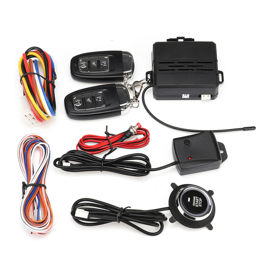
System Components ....................................1
Required Tools .......................................1
Technical Assistance .................................1
Before You Begin .....................................2
Precautions ..........................................2
Testing Your Wires ...................................2
Making Connections .................................2-4
Locating & Making Connections ......................4-5
Neutral Safety Switch ................................5
Connecting 18-Pin Harness ............................6
Connecting 4-Relay Harness ...........................6
Antenna Placement ....................................6
Anti-Theft System ....................................7
Optional Connections ...............................7-9
Operating Instructions ...............................9
Programming Instructions ..........................9-10
Technical Assistance
All tech personnel are expertly qualified to answer any technical questions.
Technicians are available Monday through Friday from 9:00 a.m. until 8:00 p.m. and Saturday 10:00 a.m. until 4:00 p.m.
Address
288 Canton Avenue • Wintersville, Ohio 43953
Telephone
Phone: 740-264-4710 • 800-878-8007 • Fax: 740-264-7306
Advertisement
Table of Contents

Related Manuals for Bulldog Security RS102


Summary of Contents for Bulldog Security RS102
-
Page 1: Table Of Contents
INSTALLATION GUIDE • OWNER’S GUIDE REMOTE STARTER MODELS RS102/RS102E, RS112/RS112E, RS122/RS122E CONTENTS System Features ........1 System Components ........1 Required Tools ........1 Technical Assistance .........1 Before You Begin ........2 Precautions ..........2 Testing Your Wires ........2 Making Connections .........2-4 Locating & Making Connections ......4-5 Neutral Safety Switch ........5 Connecting 18-Pin Harness ......6 Connecting 4-Relay Harness ......6... -
Page 2: System Features
SYSTEM FEATURES Four-Button Extended Range Remotely start your car to run the heater or air conditioning from an extended distance. Remote Control Keyless Entry Remotely locks and unlocks your power door locks. Trunk Release Remotely opens your trunk with a push of a button. (Optional part #775 required) Remote Programmable Run Time Remotely program your vehicle to run 5 to 15 minutes. -
Page 3: Before You Begin
It is computer controlled and manufactured in the U.S.A. The dependability and variety of features make Bulldog Security the leader in the industry. Enjoy your new remote starter for years to come! This remote system is designed to start your vehicle by sending a command signal from the remote transmitter or by programming automatic temperature or timed start. - Page 4 3. Separate the vehicle wire as shown. Make the separation large enough to fit the other wire through. 4. Insert the wire from the unit through the hole as shown. 5. Wrap the wire around one side then the other and finally around itself as shown. 6.
-
Page 5: Locating & Making Connections
4. Use electrical tape to wrap, be sure to cover about 2 inches on either side of connection. Secure with wire ties as shown. Electrical Tape Wire Tie Wire Tie Use this method ONLY when connecting two separate wires end to end. LOCATING &... -
Page 6: Neutral Safety Switch
To (-)Parking YELLOW PARKING LIGHTS (+12V only with parking lights on) Light Output Turn the parking lights to the ON position. (NOT YOUR HEADLAMPS). Probe the wire(s) coming from your headlamp control switch. Find a wire that will show +12V only when the parking lights are ON. WHITE BLACK Connect the BROWN wire from the 18-pin harness to this wire. -
Page 7: Connecting 18-Pin Harness
CONNECTING THE 18-PIN HARNESS & 4-RELAY HARNESS CAUTION: Before connecting the 18-pin BROWN/BLACK (+) or (-) Door Lock pulse harness to the module, double check all GREEN/BLACK (-) or (+) Door Unlock pulse connections to be sure they are secure BLACK/WHITE Tach (-) to neg. -
Page 8: Anti-Theft System
FACTORY ANTI-THEFT SYSTEMS FOR GENERAL MOTORS CARS ONLY System 1: PASSKEY I and II system (1985 and up). This system has a resistor pill in the key. Measure resistance of the pill using a test meter. A bypass module is available, part #VATS-WR module. System 2: PASSLOCK I and II system (1995 and up). - Page 9 CONNECTING “TYPE B LOCKS” • If your vehicle has a “Type B” door locking system, LOCK GREEN/BLACK connect the GREEN WITH BLACK STRIPE wire from the 18-pin harness to the door lock wire. Connect the BROWN WITH BLACK STRIPE wire to the unlock wire. See diagram below.
-
Page 10: Operating Instructions
AUXILIARY INPUT If you wish to use this starter with an aftermarket alarm, connect the BLUE wire from the 18-pin harness to the second or third channel (-) output of your existing alarm. When the output is activated, a (-) signal will be supplied to the remote starter. OPERATING INSTRUCTIONS BUTTON #1 1. - Page 11 Door Lock Pulse Length (Long) Press and hold brake. Next, press and hold Button #3, the parking lights will flash three (3) times. Release. Press and release Button #1. The parking lights will flash once, the door lock pulse length will be 3.5 seconds of output. Release the brake, the parking lights will flash three (3) times.
Need help?
Do you have a question about the RS102 and is the answer not in the manual?
Questions and answers
Se puede usar en un toyota rav 4 del 2007