Table of Contents
Advertisement
Advertisement
Table of Contents

Subscribe to Our Youtube Channel
Related Manuals for BSS Audio DPR 404


Summary of Contents for BSS Audio DPR 404
- Page 1 DPR 404 User Manual...
- Page 2 V3.0 26 July 1999 This equipment has been tested and found to comply with the following European Standards for Electromagnetic Compatibility: Emission Specification: EN55013 (1990) (Associated equipment) Immunity Specification: EN50082/1 (1992) (RF Immunity, Fast Transients and ESD) Mains Disturbance: EN61000/3/2 (1995) For continued compliance ensure that all input and output cables are wired with cable screen connected to Pin 1 of the XLR.
-
Page 3: Table Of Contents
Contents Contents The BSS DPR-404 Unpacking Mechanical Installation Earthing Requirements Mains Power Connection Audio connections Balanced wiring Unbalanced wiring Ground loop control Linked operation Controls Gain Ratio Attack/Release Below TH meter Gain reduction meter De-ess FREQ Link 8.10 Link master LED 8.11 Main power fuse Rear panel controls... - Page 4 Contents 11.0 The effect of Compression on sound 11.1 Compression 11.2 Attack, Release and Ratio 11.3 De-essing 12.0 Specifications 13.0 Service Section 13.1 Transient suppressor replacement 13.2 Separating signal and chassis ground 14.0 Warranty Information...
-
Page 5: The Bss Dpr-404
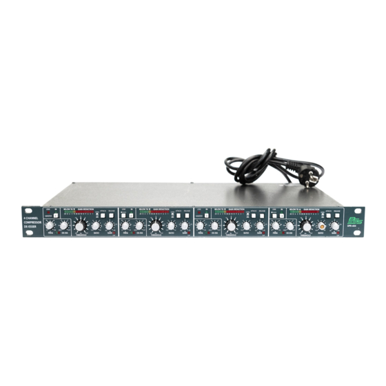
The DPR-404 The BSS DPR-404 The DPR-404 is a compact and professional four channel compressor and de- esser. Based on the well established BSS subtractive gain reduction principle, it offers you four independent channels of high quality, musical compression and high frequency de-essing, with the minimum of operator controls. Designed to be quick and easy to operate by both skilled and novice engineers alike, it makes a compact economical alternative to the fully featured DPR-402 model. -
Page 6: Unpacking
Unpacking Mechanical Installation Unpacking As part of BSS’ system of quality control, this product is carefully checked before packing, to ensure flawless appearance. After unpacking the unit, please inspect for any physical damage and retain the shipping carton and all relevant packing materials for use should the unit need returning. -
Page 7: Earthing Requirements
Earthing Requirements Earthing Requirements WARNING! THIS APPLIANCE MUST BE EARTHED. IMPORTANT: The wires in the mains lead are colour coded in accordance with the following code. Green and Yellow..Earth Blue..Neutral Brown..Live As the colours of the wires in the mains lead may not correspond with the markings identifying the terminals in your plug, proceed as follows. -
Page 8: Mains Power Connection
Mains Power connection Mains Power Connection Voltage: The DPR-404 operates on either 120 or 240 volt supplies. Use the voltage selector switch to choose the required voltage setting. (See Figure 8.1). Frequency: Both 60Hz and 50Hz are acceptable. Fig 5.1 Mains fuse on rear panel. - Page 9 Power ON: This is indicated the green 'ON' LED located under the CH 'IN' switches. If this LED is not lit when power is connected and the 'POWER' switch is depressed, see section 16.
- Page 10 Getting to know the DPR-404 Fig 6.1 Front Panel Fig 6.2 Rear Panel...
- Page 11 All numbers in bubbles refer to Section numbers.
-
Page 12: Audio Connections
Audio connections Audio connections The DPR-404 audio inputs are RFI filtered and electronically balanced, with the outputs electronically balanced and floating. They are designed to operate at any signal level up to +20dBu and will drive into loads of 600 ohms or greater. -
Page 13: Linked Operation
7.4 Linked For stereo program processing, channels 1 and 2 can be linked together by selecting the LINK switch on channel 2. Channel 1 will assume the master operation role, such that threshold, ratio, attack and release for channel two are equal to and controlled by channel 1 with the side chain controlling signal being the mono sum of both channels. -
Page 14: Controls
Controls Controls 8.1 IN When depressed the processing is engaged and the green LED lights in confirmation. When released, processing is disabled, the LED is off and the incoming signal passes to the output unchanged and at unity gain. Output level control used to restore signal after processing, providing ÿ 20dB 8.2 Gain of adjustment range. -
Page 15: Attack/Release
8.4 Attack/Release With the switches released, the function is automatically set and is program related, such that it follows the signal requirements for general vocal and mix program signals. (It closely follows the ‘auto’ mode on the DPR-402 unit). When depressed, the function is again automatically set and program related but is scaled to suit more transient program material such as percussion. -
Page 16: De-Ess
8.7 De-ess Threshold control for the high frequency de-esser circuitry. It works independently of the main compressor section and can be used simultaneously with it. It uses a second subtractive element that works to reduce only those high frequencies set by the FREQ control, leaving the other frequency content of the program unprocessed. -
Page 17: Main Power Fuse
Rear panel controls 8.11 Main power 20mm, T160mA for 240v AC voltage setting and T250mA for 120v AC voltage setting fuse Rear panel controls 9.1 Mains voltage Allows operation from 90v-130v or 190v-250v 50/60Hz AC mains voltage. selector switch 9.2 Mains power Turns the unit on/off. -
Page 18: External Side Chain Insert
Rear panel controls 9.4 External side Offers a line level insertion point, on an RTS jack, into the control side chain. Connections are: Ring: Signal output from 470 source. chain insert Tip: Return input to 10k. Sleeve: 0v ground. 9.5 Electronically Maximum input is +20dBu into 10kohms. -
Page 19: Compressors And Limiters
Compressors and Limiters 10.0 Compressors and Limiters 10.1 The need for The human ear excels in its ability to detect an extremely wide range of sound levels. These can range from the quietest whisper to the roar of a jet Gain Control aircraft. -
Page 20: Compressors And Limiters
Compressors and Limiters Fig 10.2 Operating level and Headroom It therefore becomes apparent that to get the most out of an audio system, the standard operating level must be kept as high as possible without risking distortion. One solution to this problem is for the operator of the equipment to be continuously monitoring the program, and manually adjusting the gain to suit the moment. - Page 21 In the DPR-404, gain reduction is achieved by using a proprietary subtractive circuit which minimises signal degradation and has a maximum attenuating range of 30dB. The THRESHOLD control is used to position the input program signal into the window of operating range for the circuit. Rotating the control anticlockwise from the ‘out’...
-
Page 22: The Effect Of Compression On Sound
The effect of Compression 11.0 The effect of Compression on sound 11.1 Compression Consider an input signal which is applied to two units, one having its threshold point set 10dB higher than the other. Since the compressor only affects signals that exceed the threshold level, the signal with the lower threshold applied will be more affected than the other. -
Page 23: Attack, Release And Ratio
Comparing the input and output waveforms for the compressed mode, the loudest portions of the signal have been effectively decreased in level, and if the gain control is adjusted to compensate for this, the quieter portions will be increased. The net effect, therefore, is for both ends of the dynamic spectrum to be pushed (or squeezed) towards each other. -
Page 24: De-Essing
De-essing and Peak Limiter 11.3 De-essing A common problem encountered when amplifying or recording the human voice is the large amount of high frequency energy heard as the sibilant (Sss) sound. These sounds can reach levels considerably greater than the normal voice level, and can result in signal break-up or distortion. -
Page 25: Specifications
Specifications 12.0 Specifications Input section 12k ohm electronically balanced, +20dBu (+20dBv) maximum input level via a 3 pin male XLR cable plug. Common Mode rejection: > -50dB, 20Hz to 20kHz Input section Electronically balanced and floating, capable of driving +20dBu (+20dBv) into 600 ohms or greater via an XLR female cable plug. - Page 26 Specifications Side chain insert: Rear panel RTS jack accesses side chain for inserting other equipment at line level. Connections are: Ring: Signal output from 470 ohms source Tip: Return input into 10kohms Sleeve: 0v ground Power: AC 50/60Hz 120v/240v switched externally giving operation range of 90-132v and 180-264v.
-
Page 27: Service Section
Figure 13.1 shows the suppressors location on the voltage selector board. Fig 13.1 Suppressor location !!! WARNING - Refer all servicing to qualified service personnel !!! Risk of electric shock if the unit is opened. BSS Audio accepts no responsibility for injury subsequent to opening of the unit. -
Page 28: Separating Signal And Chassis Ground
Fig 13.2 Chassis link location !!! WARNING - Refer all servicing to qualified service personnel !!! Risk of electric shock if the unit is opened. BSS Audio accepts no responsibility for injury subsequent to opening of the unit. -
Page 29: Warranty Information
14.0 Warranty Information When sold to an end user by BSS Audio or a BSS Audio Authorised Reseller, this unit is warranted by the seller to the purchaser against defects in workmanship and the materials used in its manufacture for a period of one year from the date of sale. - Page 30 Index Index Attack Time Below Threshold. See Compression meters; Compression meters: Below Threshold Chassis ground separating from signal Compression Dynamic Range Earthing Front Panel Fuses. See Mains Connection Gain Reduction. See Compression meters: Gain Reduction Getting to know the DPR-402 Grounding.
- Page 31 Index Release time Specifications Threshold Transient suppressor replacement Unpacking Warranty Info.
- Page 32 User Notes...
- Page 33 User Notes...
Need help?
Do you have a question about the DPR 404 and is the answer not in the manual?
Questions and answers