
Related Manuals for Black Box PI125A-R2


Summary of Contents for Black Box PI125A-R2
- Page 1 © Copyright 2001. Black Box Corporation. All rights reserved. 1000 Park Drive • Lawrence, PA 15055-1018 • 724-746-5500 • Fax 724-746-0746...
- Page 2 Order toll-free in the U.S. 24 hours, 7 A.M. Monday to midnight Friday: 877-877-BBOX FREE technical support, 24 hours a day, 7 days a week: Call 724-746-5500 or fax 724-746-0746 Mail order: Black Box Corporation, 1000 Park Drive, Lawrence, PA 15055-1018 Web site: www.blackbox.com • E-mail: info@blackbox.com...
- Page 4 TRADEMARKS/CE NOTICE Trademarks Used In This Manual Black Box and the logo are registered trademarks of Black Box Corporation. Centronics is a registered trademark of GENICOM Corporation. DeskJet and HP are registered trademarks of Hewlett- Packard. IBM is a registered trademark of IBM Corporation.
- Page 5 SERIAL↔PARALLEL CONVERTERS FEDERAL COMMUNICATIONS COMMISSION INDUSTRY CANADA RADIO FREQUENCY INTERFERENCE STATEMENTS This equipment generates, uses, and can radiate radio frequency energy and if not installed and used properly, that is, in strict accordance with the manufacturer’s instructions, may cause interference to radio communication. It has been tested and found to comply with the limits for a Class A computing device in accordance with the specifications in Subpart J of Part 15 of FCC rules, which are designed to provide reasonable protection against such interference...
- Page 6 NOM STATEMENT NORMAS OFICIALES MEXICANAS (NOM) ELECTRICAL SAFETY STATEMENT INSTRUCCIONES DE SEGURIDAD 1. Todas las instrucciones de seguridad y operación deberán ser leídas antes de que el aparato eléctrico sea operado. 2. Las instrucciones de seguridad y operación deberán ser guardadas para referencia futura.
- Page 7 SERIAL↔PARALLEL CONVERTERS 10. El equipo eléctrico deber ser situado fuera del alcance de fuentes de calor como radiadores, registros de calor, estufas u otros aparatos (incluyendo amplificadores) que producen calor. 11. El aparato eléctrico deberá ser connectado a una fuente de poder sólo del tipo descrito en el instructivo de operación, o como se indique en el aparato.
-
Page 8: Table Of Contents
TABLE OF CONTENTS Contents 1. Specifications ..............6 2. Introduction ..............8 2.1 Description ............8 2.2 Features..............8 3. Configuration and Installation ........10 3.1 Configuration Switches ........10 3.2 Installation ............14 4. Reading the LED ............15 5. Troubleshooting ............16... -
Page 9: Specifications
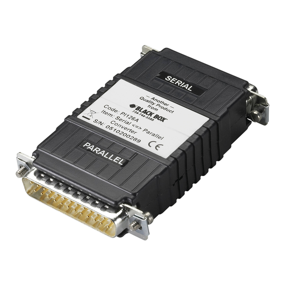
SERIAL↔PARALLEL CONVERTERS 1. Specifications Data Rates — 300, 600, 1200, 2400, 4800, 9600, 19,200, 38,400 bps Indicators — LED displays status and operating condition EIA RS-232 async serial Interface — (autosensing DTE/DCE) and IBM PC parallel Connectors — (1) DB25M, (1) DB25F Data Format —... - Page 10 CHAPTER 1: Specifications Size — 3.4"H x 1.3"W x 0.8"D (8.7 x 3.3 x 2 cm) Weight — 2 oz. (57 g)
-
Page 11: Introduction
SERIAL↔PARALLEL CONVERTERS 2. Introduction 2.1 Description ↔ Parallel Converters automatically convert The Serial RS-232 serial data to parallel data format and vice versa, in one direction at a time. Incorporating advanced microprocessor technology, they are able to automati- cally sense and select parallel and serial modes, as well as DCE/DTE modes. -
Page 12: Features
CHAPTER 2: Introduction 2.2 Features • Converts parallel data to serial data and vice versa. • Automatically selects parallel-to-serial and serial-to-parallel operation. • Automatically selects DCE/DTE modes. • Serial data rates to 38,400 bps. • No AC power required. • Supports both software and hardware flow control. •... -
Page 13: Configuration And Installation
The Converter is simple to install and extremely reliable. The following instructions will help you set up and install your converter properly. If you have any questions, please call Black Box Technical Support at 724-746-5500. 3.1 Configuration Switches The Converters each use a set of eight external DIP switches (see Figure 3-1) that allow configuration to a wide range of applications. - Page 14 CHAPTER 3: Configuration and Installation Figure 3-1. The location of the configuration switches. 1 2 3 4 5 6 7 8 Figure 3-2. The miniature configuration switch package.
- Page 15 SERIAL↔PARALLEL CONVERTERS The Converters use a miniature configuration switch package. To configure your unit, use a small screwdriver and gently push each switch to its proper setting. The ON and OFF positions are shown in Figure 3-2. Default settings (noted with an asterisk) for the DIP switches are shown in the table on the following page.
- Page 16 CHAPTER 3: Configuration and Installation Position Flow Control Hardware OFF* Software Enabled Disabled Parity/D. Bits/ S. Bit None/8/1 OFF* Odd/8/1 Even/8/1 None/7/2 Odd/7/2 Even/7/2 Odd/7/1 Even/7/1 D. Rate (bps) 1200 2400 4800 9600 OFF* 19200 38400 *Default setting.
-
Page 17: Installation
SERIAL↔PARALLEL CONVERTERS 3.2 Installation The Converter is very simple to install. Once you have configured the DIP switches, just plug your Converter into a standard cable and you’re ready to go. Figure 3-3 shows the proper connections. Figure 3-3. Typical installation. -
Page 18: Reading The Led
CHAPTER 4: Reading the LED 4. Reading the LED Once your Converter is properly configured and installed, it should operate transparently—as if it were a standard cable connection. Operating power is derived from the RS-232 data and control signals; there is no “ON/OFF”... -
Page 19: Troubleshooting
If your Serial↔Parallel Converter seems to be malfunc- tioning, do not attempt to alter or repair the unit. Contact Black Box Technical Support at 724-746-5500. Before you do so, make a record of the history of the problem. We will be able to provide more efficient and... - Page 20 NOTES...
- Page 21 NOTES...
Need help?
Do you have a question about the PI125A-R2 and is the answer not in the manual?
Questions and answers