
Related Manuals for Black Box DataBuffer Plus


Summary of Contents for Black Box DataBuffer Plus
- Page 1 © Copyright 1999. Black Box Corporation. All rights reserved. 1000 Park Drive • Lawrence, PA 15055-1018 • 724-746-5500 • Fax 724-746-0746...
- Page 2 Order toll-free in the U.S. 24 hours, 7 A.M. Monday to midnight Friday: 877-877-BBOX SUPPORT FREE technical support, 24 hours a day, 7 days a week: Call 724-746-5500 or fax 724-746-0746 INFORMATION Mail order: Black Box Corporation, 1000 Park Drive, Lawrence, PA 15055-1018 Web site: www.blackbox.com • E-mail: info@blackbox.com...
- Page 4 DATABUFFER PLUS FEDERAL COMMUNICATIONS COMMISSION INDUSTRY CANADA RADIO FREQUENCY INTERFERENCE STATEMENTS This equipment generates, uses, and can radiate radio frequency energy and if not installed and used properly, that is, in strict accordance with the manufacturer’s instructions, may cause interference to radio communication. It has been tested...
- Page 5 DATABUFFER PLUS NORMAS OFICIALES MEXICANAS (NOM) ELECTRICAL SAFETY STATEMENT INSTRUCCIONES DE SEGURIDAD 1. Todas las instrucciones de seguridad y operación deberán ser leídas antes de que el aparato eléctrico sea operado. 2. Las instrucciones de seguridad y operación deberán ser guardadas para referencia futura.
- Page 6 DATABUFFER PLUS 11. El aparato eléctrico deberá ser connectado a una fuente de poder sólo del tipo descrito en el instructivo de operación, o como se indique en el aparato. 12. Precaución debe ser tomada de tal manera que la tierra fisica y la polarización del equipo no sea eliminada.
- Page 7 DATABUFFER PLUS TRADEMARKS The trademarks mentioned in this manual are the sole property of their owners.
-
Page 8: Table Of Contents
4.2.2 X-ON/X-OFF Handshaking ......14 4.3 DataBuffer Plus Input and Output Port Pinouts ....14... -
Page 9: Specifications
DATABUFFER PLUS 1. Specifications Speed — 300 to 115,200 bps Memory — PI405, PI415, PI420, PI425 models: 128 KB; PI406, PI416, PI421, PI426 models: 256 KB; PI407, PI417, PI422, PI427 models: 512 KB; PI408, PI418, PI423, PI428 models: 1 MB; PI409, PI419, PI424, PI429 models: 2 MB Flow Control —... -
Page 10: Introduction
The DataBuffer Plus is a versatile buffering device that accepts data rapidly from your computer and sends it to a printer or plotter. The DataBuffer Plus also takes data from or sends data to other devices such as scanners and modems. The DataBuffer Plus comes in the following models: •... - Page 11 DATABUFFER PLUS • DataBuffer Plus-1M-S/P (PI418A(E))— serial-to-parallel version with 1 MB of memory. • DataBuffer Plus-1M-P/P (PI423A(E))— parallel-to-parallel version with 1 MB of memory. • DataBuffer Plus-1M-P/S (PI428A(E))— parallel-to-serial version with 1 MB of memory. • DataBuffer Plus-2M-S/S (PI409A(E))— serial-to-serial version with 2 MB of memory.
-
Page 12: Installation And Configuration
DATABUFFER PLUS 3. Installation and Configuration To install the DataBuffer Plus, simply connect the unit’s input side to your computer and the unit’s output side to your printer using the appropriate cables. The cables you use will depend on your application. Typical input and output cable order codes are listed below. -
Page 13: Configuration
Figure 3-2. DataBuffer Plus in a Parallel-to-Serial Application. 3.1 Configuration The DataBuffer Plus has one output port and one input port. Each serial port must be configured individually for speed, parity, data format, and handshaking method. Table 3-1 lists these settings. The unit is also equipped with Copy/Pause and Reset buttons on the front panel. - Page 14 DATABUFFER PLUS Table 3-1. Switch Settings (Up=Off, Down=On). Switch Position (S3 input, S4 output) Baud Rate 115200 OFF OFF OFF 57600 OFF OFF 38400 19200 9600 OFF OFF 2400 1200 Data Bits Parity Even Parity Disable Enable Flow Control Hardware...
-
Page 15: Operation
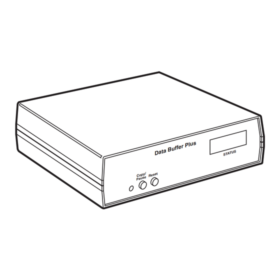
Reset also clears the copy feature (see Copy/Pause) and clears all data in the buffer. FOUR 7-SEGMENT DISPLAYS RESET COPY / PAUSE Figure 4-1. Front Panel of the DataBuffer Plus. Input Connector Output Connector DB25 female DB25 female Figure 4-2. Rear Panel of the DataBuffer Plus. -
Page 16: Leds
DATABUFFER PLUS 4.1.2 LED Four 7-segment LEDs are located on the front panel of the DataBuffer Plus. These LEDs are similar to a digital-clock display. The LEDs continuously display the amount of data in the buffer in kilobytes. These LEDs also aid you when you preset multiple copies. -
Page 17: X-On/X-Off Handshaking
When the output device cannot accept any more data, it sends an X-OFF character to Pin 2 on the DataBuffer Plus’s output port. When the output device is ready to receive more data, it sends an X-ON character via Pin 2. - Page 18 DATABUFFER PLUS Centronics ® Port Pin Configurations (DB25 Input female, Output male). Name Function Strobe Data1 Data2 Data3 Data4 Data5 Data6 Data7 Data8 Busy Select High Autofeed Fault High 19-25...
-
Page 19: Troubleshooting
Solution: For serial-to-serial or parallel-to-parallel models, try to connect the two cables connected to the unit’s input and output ports. Try to pass data through both cables. If this is unsuccessful, contact Black Box Technical Support. NOTE Parallel cables should not exceed 20 feet (6.1 m) for a valid test. Typical...
Need help?
Do you have a question about the DataBuffer Plus and is the answer not in the manual?
Questions and answers