
Related Manuals for Black Box PI035A


Summary of Contents for Black Box PI035A
- Page 1 © Copyright 1998. Black Box Corporation. All rights reserved. 1000 Park Drive • Lawrence, PA 15055-1018 • 724-746-5500 • Fax 724-746-0746...
- Page 2 Technical support and fax orders 24 hours a day, 7 days a week SUPPORT Phone orders 24 hours, 7 A.M. Monday to midnight Friday; Saturday 8 to 4 (Eastern) INFORMATION Mail order: Black Box Corporation, 1000 Park Drive, Lawrence, PA 15055-1018...
- Page 3 FEDERAL COMMUNICATIONS COMMISSION CANADIAN DEPARTMENT OF COMMUNICATIONS RADIO FREQUENCY INTERFERENCE STATEMENTS This equipment generates, uses, and can radiate radio frequency energy and if not installed and used properly, that is, in strict accordance with the manufacturer’s instructions, may cause interference to radio communication. It has been tested and found to comply with the limits for a Class A computing device in accordance with the specifications in Subpart J of Part 15 of FCC rules, which are designed to provide reasonable protection...
-
Page 4: Table Of Contents
P (SERIAL PARALLEL) CONVERTER (128K) Contents Chapter Page 1.0 Specifications ..................1 2.0 Introduction ..................2 3.0 Installation .................... 3 3.1 What You’ll Need ................3 3.2 Installation Procedures ..............8 4.0 Operation ................... 13 5.0 Troubleshooting ................. 14 5.1 Common Concerns ..............14 5.2 Calling Us .................. -
Page 5: Specifications
CHAPTER 1: Specifications 1.0 Specifications Parallel: DB25 IBM style, Centronics compatible; ® Interface — Serial: EIA RS-232 asynchronous, DTE or DCE (user-selectable) Parallel: 8 data bits; Serial: 7 data bits (even or Data Format — odd parity) or 8 data bits (no parity), user- selectable Parallel: Hardware handshaking;... -
Page 6: Introduction
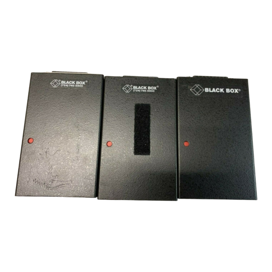
P (SERIAL PARALLEL) CONVERTER (128K) 2.0 Introduction The S P (Serial Parallel) Converter (128K) is a serial-to-parallel or parallel-to-serial converter (conversion direction is user-selectable). It operates at speeds ranging from 600 bps all the way up to 76.8 Kbps and has 128K of buffer memory, which is ideal for most ordinary print jobs and other types of file transfers. -
Page 7: Installation
CHAPTER 3: Installation 3.0 Installation 3.1 What You’ll Need Before you attach any cables or turn anything on, make sure you have everything necessary to set up your S P Converter (128K) system. Each S P Converter comes with its own power supply and a 6-foot (1.8-m) flat satin cable with RJ-45 male connectors. - Page 8 P (SERIAL PARALLEL) CONVERTER (128K) FA080-R2 (Male) FA081-R2 (Female) Pinning DB25 RJ-45 2 -------------------------------------------------------------- 5 3 -------------------------------------------------------------- 6 5, 6, 8 ------------------------------------------------------- 3 7 -------------------------------------------------------------- 4 9 -------------------------------------------------------------- 8 20 ------------------------------------------------------------ 7 (For more detail, see the Appendix) Figure 3-1. DB25 Male and Female Adapters and Required Pinning.
- Page 9 CHAPTER 3: Installation FA082-R2 Pinning RJ-45 1, 6, 8 ------------------------------------------------------- 3 2 -------------------------------------------------------------- 6 3 -------------------------------------------------------------- 5 4 -------------------------------------------------------------- 7 5 -------------------------------------------------------------- 4 (For more detail, see the Appendix) Figure 3-2. DB9 Female Adapter and Required Pinning. C. If the serial port you need to connect is not an RJ-45 female, you will also need one modular adapter conversion: To connect RJ-45 UTP to a printer’s...
- Page 10 RJ-45 TO DB25 PARALLEL MALE ADAPTER SERIAL PARALLEL PORT (FA080-R2) (FA080) CONVERTER (128K) (PI035A*) Up to 20 ft. (6.1 m) Up To 20 Ft. Up to 50 ft. (15.2 m) Up To 50 Ft. (ECN25C) (ECN25C) (EYN730MS-MM) (EYN730MS-MM) SERIAL PRINTER...
- Page 11 SERIAL PARALLEL SERIAL PARALLEL PORT CONVERTER (128K) CONVERTER (128K) (PI035A*) (PI035A*) Up to 20 ft. (6.1 m) Up to 20 ft. (6.1 m) Up To 20 Ft. Up To 20 Ft. Up to 50 ft. (15.2 m) Up To 50 Ft.
-
Page 12: Installation Procedures
P (SERIAL PARALLEL) CONVERTER (128K) EDN25C. Two DB25-female-to-RJ-45-female adapters pinned as in Figure 3-1 should be connected to the EDDC, one at each end. Our product code for these adapters is FA081-R2. Cable running from the Converters’ serial ports to these modular adapters could be the two flat satin cables that came with your units. - Page 13 CHAPTER 3: Installation • If you’re running EDDC, attach the EDDC to the Converter-end adapter and run it to your serial device. Attach its free end to the DB25 female serial port on the device or to the DB25 female connector on a second adapter.
- Page 14 P (SERIAL PARALLEL) CONVERTER (128K) Table 3-1. DIP Switch Settings for S P (Serial Parallel) Converter (128K) Option Switch Position* Baud Rate 76800 38400 19200 9600 4800 2400 1200 Data Bits/Parity 8, no parity OFF OFF 7, odd parity OFF ON 7, even parity Self-Test Normal Operation...
- Page 15 CHAPTER 3: Installation 3.2.2 C ONVERTER ROCEDURES 1. First locate each Converter within 20 feet (6.1 m) of its associated parallel device, close to a power outlet. 2. Run your parallel input cable from the PC (or whatever device is transmitting) to the input-side Converter’s parallel (DB25 female) port.
- Page 16 P (SERIAL PARALLEL) CONVERTER (128K) Set DIP switch position 8 to ON (parallel to serial conversion) on the S P Converter connected to the input (transmitting) device and to OFF (serial to parallel conversion) on the Converter connected to the output (receiving) device.
-
Page 17: Operation
CHAPTER 4: Operation 4.0 Operation Once you’ve installed the S P Converter (128K), run a few test transmissions. If one or more don’t get through intact, see Chapter 5: Troubleshooting If at any time something goes wrong with a transmission, you can press the Reset button to reset the Converter without having to unplug it or restart your devices. -
Page 18: Troubleshooting
P (SERIAL PARALLEL) CONVERTER (128K) 5.0 Troubleshooting 5.1 Common Concerns This section lists some problems that might come up during installation or operation of the S P Converter (128K), along with some solutions. 5.1.1 T ’ LED D ’ ONVERTER OWER OESN IGHT... - Page 19 CHAPTER 5: Troubleshooting 4. Check the Converter’s DTE/DCE slide switch and the word- structure and flow-control settings of its DIP switch. If they are correctly set for communication with your serial device, go to Step 5. 5. A cable run may be too long. Cable length for parallel communica- tion must not exceed 20 feet (6.1 m) between any pair of devices;...
- Page 20 P (SERIAL PARALLEL) CONVERTER (128K) or parallel cable, or an identical cable you know is OK. If communication goes smoothly for both of your devices and their associated cables when the Converter isn’t involved, go to Step 10. If there is still a problem after you make these substitutions, any of several device-related difficulties may be occurring.
- Page 21 CHAPTER 5: Troubleshooting 5. A cable run may be too long. Cable length for parallel communica- tion must not exceed 20 feet (6.1 m) between any pair of devices; serial cable length must not exceed 50 feet (15.2 m) for UTP or 500 feet (152.4 m) for extended distance data cable.
- Page 22 P (SERIAL PARALLEL) CONVERTER (128K) 11. If the problem isn’t solved, check the hardware and software configurations of the attached devices. If possible, test both of your devices by detaching them from the S P Converter and connecting them to each other with your input or output cable.
-
Page 23: Calling Us
CHAPTER 5: Troubleshooting 5.2 Calling Us If your Serial Parallel Converter (128K) seems to be malfunctioning, do not Contact us; the problem might be solvable attempt to alter or repair the unit. over the phone. Before you do, make a record of the history of the problem. We’ll be able to provide more efficient and accurate assistance if you have a complete description, including: •... -
Page 24: Appendix: Connector Pinouts
P (SERIAL PARALLEL) CONVERTER (128K) Appendix: Connector Pinouts A.1 Serial Connectors of Converter and Adapters The first column shows the pinning of the S P Converter’s RJ-45 connector, the second column shows the pinning of the DB25 connectors of the FA080-R2 and FA081-R2 adapters, and the third column shows the pinning of the FA082-R2 adapter’s DB9 connector. - Page 25 APPENDIX: Connector Pinouts A.2 The Converter’s Parallel Connector This pinout is not affected by whether the Converter is set as DCE or DTE. Pin No. Function Direction, Converter set for: Serial to Parallel* Parallel to Serial Strobe From Converter To Converter Data Bit 1 From Converter To Converter...
- Page 26 NOTES...