Table of Contents
Advertisement
Quick Links
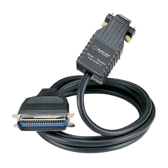
Serial↔Parallel Converter V
Serial↔Parallel Converter V-DB25
CUSTOMER SUPPORT INFORMATION
Order toll-free in the U.S.: Call 877-877-BBOX (outside U.S. call 724-746-5500)
FREE technical support 24 hours a day, 7 days a week: Call 724-746-5500 or fax 724-746-0746
Mailing address: Black Box Corporation, 1000 Park Drive, Lawrence, PA 15055-1018
Web site: www.blackbox.com • E-mail: info@blackbox.com
FEBRUARY 1998
PI045A
PI046A
Advertisement
Table of Contents

Related Manuals for Black Box PI045A


Summary of Contents for Black Box PI045A
- Page 1 Order toll-free in the U.S.: Call 877-877-BBOX (outside U.S. call 724-746-5500) FREE technical support 24 hours a day, 7 days a week: Call 724-746-5500 or fax 724-746-0746 Mailing address: Black Box Corporation, 1000 Park Drive, Lawrence, PA 15055-1018 Web site: www.blackbox.com • E-mail: info@blackbox.com...
- Page 2 SERIAL↔PARALLEL CONVERTER V AND V-DB25 FEDERAL COMMUNICATIONS COMMISSION AND CANADIAN DEPARTMENT OF COMMUNICATIONS RADIO FREQUENCY INTERFERENCE STATEMENTS This equipment generates, uses, and can radiate radio frequency energy and if not installed and used properly, that is, in strict accordance with the manufacturer’s instructions, may cause interference to radio communication.
- Page 3 SERIAL↔PARALLEL CONVERTER V AND V-DB25 NORMAS OFICIALES MEXICANAS (NOM) ELECTRICAL SAFETY STATEMENT INSTRUCCIONES DE SEGURIDAD 1. Todas las instrucciones de seguridad y operación deberán ser leídas antes de que el aparato eléctrico sea operado. 2. Las instrucciones de seguridad y operación deberán ser guardadas para referencia futura.
- Page 4 SERIAL↔PARALLEL CONVERTER V AND V-DB25 10. El equipo eléctrico deber ser situado fuera del alcance de fuentes de calor como radiadores, registros de calor, estufas u otros aparatos (incluyendo amplificadores) que producen calor. 11. El aparato eléctrico deberá ser connectado a una fuente de poder sólo del tipo descrito en el instructivo de operación, o como se indique en el aparato.
-
Page 5: Table Of Contents
SERIAL↔PARALLEL CONVERTER V AND V-DB25 Contents Chapter Page 1. Specifications............1 2. Introduction ............3 2.1 Description ...........3 2.2 Features............4 3. Configuration ............5 3.1 Configuration Switches........5 3.2 Detailed Switch Settings ......7 4. Installation ............9 5. Operation ............10 Appendix A. Interface Connections ....12 Appendix B. -
Page 6: Specifications
SERIAL↔PARALLEL CONVERTER V AND V-DB25 1. Specifications Interface Async, RS-232C compatible Connectors PI045A—Serial: DB9 female; Parallel: Centronics 36-pin male; PI046A—Serial: DB9 female; Parallel: DB25 male 6-foot (1.8-m) integral cable Cables Data Rates Up to 38,400 bps, selected by external DIP switch... - Page 7 SERIAL↔PARALLEL CONVERTER V AND V-DB25 32° to 140°F (0° to 60°C) Temperature Humidity Up to 95%, noncondensing Up to 10,100 feet (3078 m) Altitude Size 2.7"H x 1 ⁄ "W x ⁄ "D (6.9 x 3.2 x 1.9 cm) 2 oz. (56.7 g) Weight...
-
Page 8: Introduction
SERIAL↔PARALLEL CONVERTER V AND V-DB25 2. Introduction 2.1 Description The Serial↔Parallel Converter V and V-DB25 automatically convert RS-232C serial data to parallel-data format and vice versa. Incorporating advanced microprocessor technology, the Converters are able to automatically sense and select parallel and serial modes. Requiring no AC power or batteries, the Serial↔Parallel Converters support serial data rates up to 38.4 Kbps. -
Page 9: Features
SERIAL↔PARALLEL CONVERTER V AND V-DB25 a DB25 male connector on the parallel side. A six- foot (1.8-meter) integral cable is also included. 2.2 Features •Converts parallel data to serial data and vice versa •Automatically selects parallel-to-serial and serial-to-parallel operation •Serial data rates to 38,400 bps •No AC power or batteries required •Supports both software and hardware flow control... -
Page 10: Configuration
SERIAL↔PARALLEL CONVERTER V AND V-DB25 3. Configuration The Converter is simple to install and designed for excellent reliability: just set it and forget it. 3.1 Configuration Switches The Serial↔Parallel Converter V or V-DB25 uses a set of eight external DIP switches (see Figure 3-1) that allow configuration for a wide range of applications. - Page 11 SERIAL↔PARALLEL CONVERTER V AND V-DB25 Configuration Switches Figure 3-1. The location of the configuration switches. The Serial↔Parallel Converter V uses a miniature configuration-switch package. To configure your unit, use a small screwdriver and gently push each switch to its proper setting. The ON and OFF positions are shown below.
-
Page 12: Detailed Switch Settings
SERIAL↔PARALLEL CONVERTER V AND V-DB25 3.2 Detailed Switch Settings This section describes the function of each DIP switch and lists all possible settings. Switch 1: Hardware/Software Control The setting for Switch 1 determines whether these interface converters will control either hardware or software flow control. - Page 13 SERIAL↔PARALLEL CONVERTER V AND V-DB25 Data Parity Stop Bit Switches 6 through 8: Frequency and Data Rate Switches 6 through 8 determine the frequency and data rate. The chart below shows the settings that may be used. Data Rate 1200 2400 4800 9600...
-
Page 14: Installation
SERIAL↔PARALLEL CONVERTER V AND V-DB25 4. Installation The Converter is very simple to install. Once you have configured the DIP switches, just plug it in like a normal cable and you’re ready to go. The figure below illustrates the proper connections for the standard cables. -
Page 15: Operation
SERIAL↔PARALLEL CONVERTER V AND V-DB25 5. Operation Once your Converter is properly configured and installed, it should operate transparently—as if it were a standard cable connection. Operating power is derived from the RS-232 data and control signals; there is no “ON/OFF” switch. The Serial↔Parallel Converter features an easy-to- read status LED that glows red to indicate the condition of the transmission line. - Page 16 SERIAL↔PARALLEL CONVERTER V AND V-DB25 LED Codes ••-•—••-•— Computer is sending data. •—•—•— Serial device is connected; computer is not sending data. ••—••— Both serial and parallel devices are connected; Computer not sending data. •-•—•-•— Printer not ready, data held in buffer.
-
Page 17: Appendix A. Interface Connections
SERIAL↔PARALLEL CONVERTER V AND V-DB25 Appendix A. Interface Connections Centronics Interface (PI045A) Ground -19 1- Strobe (Output) Ground -20 2- Data bit 0 (I/O) Ground -21 3- Data bit 1 (I/O) Ground -22 4- Data bit 2 (I/O) Ground -23... - Page 18 SERIAL↔PARALLEL CONVERTER V AND V-DB25 DB9 Interface (PI045A and PI046A) 1- Carrier Detect (CD) Data Set Ready (DSR) -6 2- Receive Data (RD) Ready To Send (RTS) -7 3- Transmit Data (TD) Clear To Send (CTS) -8 4- Data Terminal Ready (DTR)
-
Page 19: Appendix B. Block Diagram
SERIAL↔PARALLEL CONVERTER V AND V-DB25 Appendix B. Block Diagram 100K PULL UP NETWORK DATA BIT 1 Parallel DATA BIT 2 Interface DATA BIT 3 DCE Port DATA BIT 4 DATA BIT 5 Centronics DATA BIT 6 PARALLEL or DB25 DATA BIT 7 SERIAL Connector DATA BIT 8... - Page 20 © Copyright 2002. Black Box Corporation. All rights reserved. 1000 Park Drive • Lawrence, PA 15055-1018 • 724-746-5500 • Fax 724-746-0746...
Need help?
Do you have a question about the PI045A and is the answer not in the manual?
Questions and answers