Renault Espace Driver's Handbook Manual
Hide thumbs
Also See for Espace:
- Quick manual (24 pages) ,
- Technical note (64 pages) ,
- Driver's handbook manual (314 pages)
Table of Contents
Advertisement
Quick Links
Advertisement
Chapters
Table of Contents

Related Manuals for Renault Espace


Summary of Contents for Renault Espace
- Page 1 ESPACE DRIVER’S HANDBOOK...
- Page 2 Warning: to ensure the engine operates optimally, the use of a lubricant may be restricted to certain vehicles. Please ELF has developed a complete range of lubricants for RENAULT: refer to your maintenance document. engine oils manual and automatic gearbox oils Benefiting from the research applied to Formula 1, lubricants are very high-tech products.
-
Page 3: Driving
This handbook may also contain information about items of equipment to be introduced later in the model year. Throughout the manual, the “approved Dealer” is your RENAULT Dealer. Enjoy driving your new vehicle. - Page 5 Sections Getting to know your vehicle ....... Driving ..............Your comfort ............Maintenance ............Practical advice ............ Technical specifications ........Alphabetical index ..........
-
Page 7: Table Of Contents
RENAULT card: general information, use, deadlocking ........ -
Page 8: Battery Life
Section 3); ing, etc. It is therefore advisable always – operation of certain devices (e.g.: to keep the same RENAULT card so radio, electrically controlled seats, that you can recall your personal set- etc.);... -
Page 9: Doors
Do not keep the RENAULT card in a place where it could be bent or damaged accidentally, such as in a back pocket of a garment. - Page 10 “Hands-free” renaULT card: general information (3/3) replacement: need for an additional renaULT card If you lose your RENAULT card or require another, you can obtain one from an approved dealer. If a RENAULT card is replaced, it will be necessary to take the vehi-...
-
Page 11: Locking The Doors
Operation in manual mode With the doors closed, walk away from If you wish, you can exit the hands-free the vehicle carrying your RENAULT mode by pressing button 1 or 2; you will card: the doors will lock automatically. then switch to manual mode and the... - Page 12 To unlock the doors, you must press times to indicate that the vehicle is button 1 (refer to the information on the locked. “Hands-free RENAULT card: use"). note: deadlocking is not possible if the Hands-Free mode returns automati- hazard warning lights or the side lights cally each time the vehicle ignition is are lit.
- Page 13 Once the doors have been unlocked, or Pull handle 2. electric windows or locking the with the hands-free RENAULT card on doors. your person, pull handle 1 towards you Lights-on warning buzzer to open the door.
-
Page 14: Child Safety
OPenInG and cLOsInG THe dOOrs (continued) safety of rear occupants The driver can authorise operation of the rear doors child safety Vehicles not fitted with switch 3 and, depending on the ve- To make it impossible for the rear doors hicle, the electric windows by press- Vehicles fitted with switch 3 with to be opened from the inside, move... - Page 15 – use of appliances operating on the same frequency as the card (mobile phone, etc.); – when the RENAULT card battery is drained, flat battery, etc. It is then possible: Unlocking using integrated Insert the key 2 into the lock and lock or –...
- Page 16 LOcKInG/UnLOcKInG THe dOOrs (2/3) Unlocking using separate Locking the doors manually emergency key 3 Turn the screw 4 with the door open (depending on vehicle) (using a tool such as a flat blade screw- driver) and close the door. Insert key 3 in the left-hand side door and lock or unlock the door.
- Page 17 For example, in the event of a dis- When the ignition is switched on, the charged battery or if the RENAULT card indicator light integrated in switch 5 in- is temporarily not working, etc. forms you of the status of the doors and...
-
Page 18: Operating Principle
(raId) Operating faults You can decide whether you want to activate this function. If you notice an operating fault (auto- matic locking impossible), first check Operating principle that all doors are correctly locked. If they are correctly locked and the fault... -
Page 19: Engine Immobiliser System
IMMOBILIser This prevents the vehicle from being started by anyone not in possession of the vehicle’s renaULT card. The vehicle is automatically protected a few seconds after the engine is switched off. Operating principle If the vehicle does not recognise the... - Page 20 Indicator lights If the RENAULT card is faulty (card reader and warning light 1 flashing rap- Vehicle protection tell-tale light idly), use the second RENAULT card (supplied with the vehicle) if possible.
-
Page 21: Front Headrests
frOnT HeadresTs To adjust the angle of the headrest Depending on the vehicle, tilt section A towards or away from you to the re- quired position. To remove the headrest Raise the headrest to its highest po- sition (tilt the seatback backwards if necessary). - Page 22 frOnT seaTs WITH ManUaL cOnTrOL To move forwards or backwards To adjust the driver’s seat height: Lift lever 1 to unlock the seat. When the Move lever 3 as many times as neces- seat is in the required position, release sary: We would advise you not the lever and ensure that the seat is...
- Page 23 RENAULT Card. Pull handle 4. The system operates: – hands-free RENAULT card de- tected or, depending on the vehicle, RENAULT remote control in ‘acces- sories’ position in the card reader; – for vehicles with button 2, this also...
-
Page 24: Storing The Driver's Seat Position
RENAULT Card used are automati- When driving, it is possible to adjust cally recalled when the doors are un- the driving position, but it is not possible locked and opened using the RENAULT to recall a driving position. - Page 25 frOnT arMresTs/HeaTed seaTs armrests Heated seats With the engine running, press adjustment switch 2. The indicator light in the If the vehicle is fitted with this, lift arm- switch lights up. rest 1 fully. Lower it fully then raise it to The system, which has a thermostat, the desired height.
-
Page 26: Seat Belts
seaT BeLTs (1/3) adjusting your driving Always wear your seat belt when trav- elling in your vehicle. You must also position comply with the legislation of the par- – sit well back in your seat (having ticular country you are in. removed your coat or jacket etc.). - Page 27 seaT BeLTs (2/3) ç front seat belt reminder warning light If this warning light on the instrument panel or the dashboard goes out, the front seat belts have been correctly fas- tened. Unfastening Press button 4 on buckle 5 and the seat belt will be rewound by the inertia reel.
- Page 28 seaT BeLTs (3/3) The following information applies to the vehicle’s front and rear seat belts. – No modification may be made to the component parts of the originally fitted restraint system: belts, seats and their mountings. For special operations (e.g. fitting child seats), contact an authorised dealer. –...
-
Page 29: Methods Of Restraint In Addition To The Front Seat Belts
MeTHOds Of resTraInT In addITIOn TO THe frOnT seaT BeLTs (1/4) These are: – Have the entire restraint – buckle pretensioners, system checked following an accident. – lap belt pretensioners in the front seats, – No operation whatso- ever is permitted on any part of –... - Page 30 MeTHOds Of resTraInT In addITIOn TO THe frOnT seaT BeLTs (2/4) force limiter Each air bag system consists of: – an air bag and gas generator fitted Above a certain level of impact force, on the steering wheel for the driver this mechanism is used to limit the force and in the dashboard for the front of the belt against the body so that it is...
- Page 31 MeTHOds Of resTraInT In addITIOn TO THe frOnT seaT BeLTs (3/4) Operating faults å This warning light will light up on the instrument panel when the ignition is switched on and then go out after a few seconds. If it does not light up when the ignition is switched on, or comes on when the engine is running, there is a fault in the system.
- Page 32 MeTHOds Of resTraInT In addITIOn TO THe frOnT seaT BeLTs (4/4) all of the warnings below are given so that the air bag is not obstructed in any way when it is inflated and also to prevent the risk of serious injuries caused by items which may be dislodged when the air bag inflates. Warnings concerning the driver’s air bag –...
-
Page 33: Side Protection Devices
sIde PrOTecTIOn deVIces curtain air bags B Depending on the vehicle, a mark- These are fitted on both upper sides of ing on the windscreen informs you the vehicle. They deploy along the front of the presence of additional means and rear side windows to protect oc- of restraint (air bags, pretensioners, cupants in the event of a severe side... -
Page 34: Additional Methods Of Restraint
addITIOnaL MeTHOds Of resTraInT all of the warnings below are given so that the air bag is not obstructed in any way when it is inflated and also to prevent the risk of serious injuries caused by items which may be dislodged when the air bag inflates. The air bag is designed to complement the action of the seat belt. -
Page 35: Child Safety: General Information
cHILd safeTY: General information (1/2) carrying children Children, and adults, must be correctly seated and strapped in for all journeys. The children being carried in your vehi- cle are your responsibility. A child is not a miniature adult. Children are at risk of specific injuries as their muscles and bones have not yet fin- driver’s responsibility ished growing. - Page 36 cHILd safeTY: General information (2/2) Using a child seat Set a good example by always fas- The level of protection offered by the tening your seat belt and teaching child seat depends on its ability to re- your child: strain your child and on its installation. –...
- Page 37 cHILd safeTY: choosing a child seat rear-facing child seats forward-facing child seats Booster cushions A baby’s head is, proportionally, heavier The child’s head and abdomen need to From 15 kg or 4 years, the child can than that of an adult and its neck is very be protected as a priority.
-
Page 38: Choosing A Child Seat Mounting
cHILd safeTY: choosing a child seat mounting (1/2) There are two ways of attaching child attachment using the IsOfIX Do not use the child seat seats: via the seat belt or using the system if it may unfasten the seat ISOFIX system. - Page 39 cHILd safeTY: choosing a child seat mounting (2/2) To access ring 3, lower cover 4 shown by a marking on the back of the seat. Fix the hook of the strap onto ring 3 and pull the strap so that the seatback of the child seat comes into contact with the seatback of the vehicle seat.
-
Page 40: Fitting A Child Seat
cHILd safeTY: fitting a child seat (1/4) In the rear seat Some seats are not suitable for fitting In the front seat child seats. The diagram on the follow- The laws concerning children travel- A carrycot can be installed across the ing page shows you how to attach a ling in the front passenger seat differ in vehicle and will take up at least two... - Page 41 cHILd safeTY: fitting a child seat (2/4) child seat attached using the IsOfIX mounting ü Seat which allows an ISOFIX child seat to be fitted. ± The rear seats are fitted with an anchorage point which allows a forward-facing ISOFIX child seat with universal approval to be fitted.
- Page 42 cHILd safeTY: fitting a child seat (3/4) The table below summarises the information already shown on the diagram on the previous page, to ensure the regula- tions in force are respected. seats suitable for fitting a child seat seat size Weight of Type of child seat the child...
- Page 43 cHILd safeTY: fitting a child seat (4/4) X = Seat not suitable for fitting child seats. U = Seat which allows a child seat with “Universal” approval to be installed using a seat belt; check that it can be fitted. IUf/IL = On equipped vehicles, seat which allows an approved “Universal”/“semi-universal”...
-
Page 44: Deactivating/Activating The Front Passenger Airbag
cHILd safeTY: deactivating/activating the front passenger air bag (1/3) deactivating the front To deactivate the air bags: when the vehicle is stationary, push and turn passenger air bags lock 1 to the Off position. (on equipped vehicles) With the ignition on, you must check You must deactivate the devices in ad- ã... - Page 45 cHILd safeTY: deactivating/activating the front passenger air bag (2/3) The markings on the dashboard and labels A on each side of passenger sun blind 3 (example: label shown above) remind you of these instructions. danGer Since operation of the front passenger air bag is not compatible with the position of a rear-facing child seat, neVer...
- Page 46 cHILd safeTY: deactivating/activating the front passenger air bag (3/3) danGer Since operation of the front passenger air bag is not compatible with the position of a rear-facing child seat, neVer fit a rear-facing child seat on a front passenger seat with an active front air bag.
-
Page 47: Steering Wheel
sTeerInG WHeeL/POWer-assIsTed sTeerInG Power-assisted steering With the engine running, do not leave the steering wheel at full lock while sta- tionary as this may damage the power- assisted steering pump. With the engine switched off, or if there is a system fault, it is still pos- sible to turn the steering wheel. - Page 48 drIVer’s POsITIOn, LefT-Hand drIVe 9 10 11 15 16 28 27 26 19 18 17 21 20 1.42...
-
Page 49: Instrument Panel
– cruise control and speed limiter. 8 Controls for: 18 Lower centre storage compart- – windscreen and rear screen 27 Assisted parking brake. wash/wipe; ment. – trip computer and warning 28 Bonnet release control. 19 Gear lever. system information readout. RENAULT card reader. 1.43... - Page 50 drIVer’s POsITIOn, rIGHT-Hand drIVe 10 11 14 15 18 17 1.44...
- Page 51 2 Heating and ventilation controls. 12 Radio remote control. 20 Gear lever. 3 Air vent. 13 Controls for: 21 RENAULT card reader. 4 Location for passenger air bag. – windscreen and rear screen wash/wipe; 22 Multimedia equipment controls 5 Left-hand upper storage compart- –...
- Page 52 WarnInG LIGHTs (1/4) The presence and operation of the warning lights dePend On THe eQUIPMenT and cOUnTrY. á Headlight main beam indica- tor light dipped beam headlight tell- tale light side light indicator light front fog light tell-tale light rear fog light tell-tale light Ã...
- Page 53 WarnInG LIGHTs (2/4) The presence and operation of the warning lights dePend On THe eQUIPMenT and cOUnTrY. û Ú À sTOP light Battery charge warning light Oil pressure warning light This lights up when the ignition This comes on when the This comes on when the is switched on and goes out as soon as engine is started then goes out as soon...
- Page 54 WarnInG LIGHTs (3/4) The presence and operation of the warning lights dePend On THe eQUIPMenT and cOUnTrY. ú ç å Warning light driver or front passenger air bag warning light This lights up when the ignition seat belt reminder warning This comes on when the igni- is switched on and goes out as soon as light...
- Page 55 WarnInG LIGHTs (4/4) The presence and operation of the warning lights dePend On THe eQUIPMenT and cOUnTrY. Ì speed limiter and cruise Low fuel level warning light control warning light This comes on when the igni- See the information on the “Speed lim- tion is switched on and goes out after a iter”...
-
Page 56: Rev Counter
InsTrUMenT PaneL: displays and indicators rev counter 1 Instrument panel in miles: To return to the previous mode, repeat the operation. (scale × 1,000) it is possible to switch to km/h. note: once the battery is disconnected, – with the ignition off, press button 3 the trip computer and warning system speedometer 2 and start button 4;... -
Page 57: Coolant Temperature
InsTrUMenT PaneL: displays and indicators (continued) coolant temperature fuel gauge 7 Information display 8 indicator 6 The number of lit squares shows the re- Depending on the vehicle, it includes: maining fuel level. Under normal use, the level must be –... -
Page 58: Trip Computer And Warning System
TrIP cOMPUTer: general information (1/2) display selection keys 2 c) mileage before service, d) Tyre pressures, Scroll through the following information by brief successive presses. e) empty display (no message on the display), a) total mileage and trip mileage re- corder, f) programmed speed (speed limiter/ cruise control),... - Page 59 TrIP cOMPUTer: general information (2/2) Interpreting some of the – You may also notice that the aver- age fuel consumption increases values displayed after when the vehicle is stationary and resetting the engine idling. The values showing average fuel con- This is normal, since the computer sumption, range and average speed takes account of fuel used during...
- Page 60 TrIP cOMPUTer: trip settings (1/4) The display of information shown below dePends On THe VeHIcLe eQUIPMenT and cOUnTrY. examples of selections Interpreting the display selected a) Total mileage and trip mileage recorder. FUEL USED b) Journey parameters. 37.1 L Fuel consumed since the last reset. average fuel consumption since the last reset.
- Page 61 TrIP cOMPUTer: trip settings (2/4) The display of information shown below dePends On THe VeHIcLe eQUIPMenT and cOUnTrY. examples of Interpreting the display selected selections estimated range with remaining fuel RANGE This range takes into account the average fuel consumption since the last time the 623 KM reset button was pressed.
- Page 62 TrIP cOMPUTer: trip settings (3/4) The display of information shown below dePends On THe VeHIcLe eQUIPMenT and cOUnTrY. examples of selections Interpreting the display selected c) Oil change interval Distance remaining until the next oil change (displayed in miles/kilometres and SERVICE DUE months), then when the time nears, several scenarios are possible: –...
- Page 63 TrIP cOMPUTer: trip settings (4/4) The display of information shown below dePends On THe VeHIcLe eQUIPMenT and cOUnTrY. examples of Interpreting the display selected selections FRONT TYRES d) Tyre pressure (refer to the information on the “Tyre pressure monitor” in section 2). 2.3 2.1 e) empty screen There will be no display on the screen when you select this page.
- Page 64 TrIP cOMPUTer and WarnInG sYsTeM: information messages These can help in the vehicle starting phase, or give information about a selection or a driving status. Examples of information messages are given in the following pages. Messages Interpretation of messages « aUTO LIGHTs fUncTIOn Indicates that the automatic lights function is deactivated.
- Page 65 TrIP cOMPUTer: operating fault messages (1/2) ú These appear with the warning light and mean that you should drive very carefully to an approved dealer as soon as possible. If you fail to follow this recommendation, you risk damaging your vehicle. ú...
- Page 66 « cHecK GearBOX » possible. The RENAULT hands-free card is not in the detection zone, or the vehicle has not been « card nOT deTecTed » able to detect it. Insert it in the reader; if the fault persists contact your approved Dealer.
- Page 67 TrIP cOMPUTer warning messages (1/2) û These appear with the warning light and require you to stop immediately, for your own safety, as soon as traffic conditions allow. stop your engine and do not restart it. contact an approved dealer. Examples of warning messages are given in the following pages.
- Page 68 TrIP cOMPUTer warning messages (2/2) û These appear with the warning light and require you to stop immediately, for your own safety, as soon as traffic conditions allow. stop your engine and do not restart it. contact an approved dealer. Examples of warning messages are given in the following pages.
-
Page 69: Clock And Exterior Temperature
cLOcK and eXTerIOr TeMPeraTUre external temperature indicator special note: When the outside temperature is –3°C to +3°C, the °C characters flash (signal- ling a risk of black ice on the road). When the ignition is switched on, the clock and (depending on vehicle) exter- nal temperature are displayed. - Page 70 dOOr MIrrOrs Heated door mirrors With the engine running, mirror de- icing is activated simultaneously with rear screen de-icing/demisting. adjustment folding door mirrors With the ignition on, turn button 1: Turn button 1 to position F and the door mirrors fold in. –...
-
Page 71: Rear-View Mirrors
rear VIeW MIrrOrs Interior rear view mirror auto-dimming rear view mirror Its position can be adjusted. When driv- ing at night, to avoid being dazzled by The rear view mirror 2 darkens auto- the headlights of the vehicle behind, matically at night when you are fol- depress the little lever 1 located behind lowed by a vehicle using main beam the rear view mirror. -
Page 72: Audible And Visual Signals
aUdIBLe and VIsUaL sIGnaLs Horn Hazard warning lights direction indicators é Press steering wheel boss A. Press switch 2. Move stalk 1 parallel to the steering This switch activates all four direction wheel and in the direction you are going indicators and the side indicator lights to turn it. -
Page 73: Exterior Lighting And Signals
– The lights go out when the engine is stopped, when the driver’s door is opened or when the vehicle is locked with the RENAULT card. Manual operation side lights dipped beam Turn the end of stalk 1 until the symbol headlights is opposite mark 3. - Page 74 With the ignition off and the RENAULT card removed from the reader, pull stalk 1 towards you: the dipped beam headlights come on for approximately thirty seconds.
-
Page 75: Front Fog Lights
eXTerIOr LIGHTInG and sIGnaLs (3/3) special case Using the front and/or rear fog front fog lights rear fog lights lights when automatic operation of dipped headlights is activated. With the lights on, turn centre With the lights on, turn ring 5 on the stalk until the symbol centre ring 5 on the stalk until the Turning on the fog lights faces mark 6. -
Page 76: Electric Beam Height Adjustment
eLecTrIc BeaM HeIGHT adJUsTMenT examples of the adjustment position of control A standard chassis Long chassis 5 seater 7 seater 5 seater 7 seater driver alone or with front passenger driver with a front passenger On equipped vehicles, control A allows and passengers in the rear you to adjust the height of the beams according to the load. -
Page 77: Windscreen Wipers
WIndscreen WasH/WIPe (1/2) Vehicle fitted with front windscreen wiper rain sensor With the ignition on, move stalk 1 A park B “automatic wiper function” posi- tion When this position is selected, the system detects water on the wind- screen and triggers the wipers at a suitable wiping speed. -
Page 78: Windscreen Washer
WIndscreen WasH/WIPe (2/2) In frosty weather, make sure that the wiper blades are not stuck by ice (risk of motor overheating). If the wipers do not work, contact an Windscreen washer, approved dealer. When working in the engine compartment, ensure that headlight washers Keep an eye on the condition of the the windscreen wiper stalk... -
Page 79: Special Note
rear screen WasH/WIPe Check the condition of the wiper blades. You are responsible for their service life: – they must remain clean: clean the blades, windscreen and rear screen regularly with soapy water; – do not use them when the wind- screen or rear screen are dry;... -
Page 80: Diesel Versions
fUeL TanK (1/3) fuel grade Use a high-grade fuel that complies with the legislation in force in each country and which complies with the specifications given on the label C on cover A. Please refer to the information on “Engine specifications” in Section 6. diesel versions It is essential to use diesel fuel that conforms with the information given on... - Page 81 fUeL TanK (2/3) Vehicles running on ethanol- filling with fuel Persistent smell of based fuel Insert the nozzle to open valve B and fuel insert it fully before turning it on to fill It is essential to use unleaded petrol or If you notice a persistent the fuel tank (risk of splashing).
- Page 82 TanK (3/3) special circumstances If the RENAULT card is faulty, it is pos- sible to unlock flap A by manually op- erating unlocking rod 1 (inside the lug- gage compartment). 1.76...
- Page 83 Section 2: Driving (Advice on use relating to fuel economy and the environment) Running in ..............Starting/stopping the engine .
-
Page 84: Running In
RUNNING IN – Petrol version – Diesel version For the first 600 miles (1,000 km), do For the first 900 miles (1,500 km), not exceed 78 mph (130 km/h) in the do not exceed 2,500 rpm. After com- highest gear, or 3,000 to 3,500 rpm. pleting this mileage you may drive faster, although you may only expect You may only expect top performance... -
Page 85: Starting/Stopping The Engine
“Stop”, “Accessories” and “+ Starting the engine reader. Otherwise, the child could After ignition feed” positions With the RENAULT card inside the ve- start the engine or operate electrical hicle (area A) but not in high-up areas equipment such as the electric win-... - Page 86 Warning light 2 and card reader 3 flash. In both cases, the pedal must be de- may be affected by interference With the RENAULT card fully inserted in pressed throughout the engine starting from nearby devices, such as exte- card reader 3 (until the steering column phase.
- Page 87 1. Once the engine starts, light 1 goes out (the RENAULT is then locked in the card reader, whose light goes out). If there is a child (or a Stopping the engine...
-
Page 88: Special Features Of Petrol Versions
SPEcIAL FEATURES OF PETROL vERSIONS The following operating conditions If you notice any of the above operating should be avoided: faults, have the necessary repairs car- ried out as soon as possible by an ap- – driving for long periods when the low proved dealer. -
Page 89: Running Out Of Fuel
SPEcIAL FEATURES OF DIESEL vERSIONS Diesel engine speed Running out of fuel Precautions to be taken in winter Diesel engines are fitted with injection After filling the tank if you have run equipment which prevents the engine completely out of fuel, the engine To avoid faults in icy weather: speed being exceeded irrespective of may be started normally on condition... -
Page 90: Applying The Assisted Parking Brake
ASSISTED PARKING BRAKE Indicator light 2 on the dashboard and indicator light 3 on the instrument panel light up to confirm that the assisted parking brake is applied. Indicator lights 3 and 2 go out when the doors are locked. Depending on the vehicle, the “parking brake applied”... - Page 91 – pull handle 1 while pressing unlock- Indicator lights 2 on the dashboard ing button 4 and then release; and 3 on the instrument panel light – remove the RENAULT card from the up to confirm that it has been ap- card reader. plied.
-
Page 92: Emergency Unlocking
RENAULT card in the card reader or passenger com- partment. They could release the parking brake and cause the vehicle to move off unintentionally. -
Page 93: Gear Lever
GEAR LEvER/POWER-ASSISTED STEERING Power-assisted steering The reversing lights will come on as soon as reverse gear is selected with If you have power-assisted steering the ignition on. fitted, do not leave the steering wheel Vehicles fitted with parking distance at full lock while stationary as this may control: refer to the information on the damage the pump. -
Page 94: Engine Adjustments
ADvIcE: antipollution, fuel economy and driving Maintenance Engine adjustments Your vehicle complies with criteria for recycling and recovering vehicles at the – ignition: this does not require ad- It is important to remember that failure to end of their service life which will come justment. - Page 95 ADvIcE: antipollution, fuel economy and driving (continued) Exhaust gas monitoring – Brake as little as possible by suitably anticipating an obstacle or bend and system then simply releasing the accelerator The exhaust gas monitoring system will pedal. detect any operating faults in the vehi- –...
- Page 96 ADvIcE: antipollution, fuel economy and driving (continued) – In vehicles fitted with air condi- tioning, it is normal to observe an increase in fuel consumption (es- pecially in city conditions) when it is used. For vehicles fitted with manual air conditioning, switch off the system when it is not required.
-
Page 97: Environment
– In all cases, comply with local legis- use, and therefore to consume less fuel This commitment is illustrated by the lation. (eg. 140 g/km, equivalent to 5.3 l/100 Renault eco² signature. km for a diesel vehicle). Recycling Our vehicles are also equipped with a Manufacture... -
Page 98: Tyre Pressure Monitor
TYRE PRESSURE MONITOR The tyre pressures can be adjusted If the vehicle is equipped with the func- tion, this system monitors the tyre pres- when cold (refer to the information on sure. “Tyre pressure” for the values). If tyre pressures cannot be checked Operating principle when the tyres are cold, the normal pressures must be increased by 0.2 to... - Page 99 TYRE PRESSURE MONITOR Fitting tyres (replacing tyres or fitting winter tyres) Since replacing tyres requires special precautions, we advise you to contact your approved dealer. Reading the tyre pressure on the in- strument panel (if fitted to the vehicle). After the vehicle’s tyre pressures have been checked, the warning messages on the instrument panel and/or the values read on the trip computer and...
- Page 100 TYRE PRESSURE MONITOR Emergency spare wheel The emergency spare wheel has no sensor, and cannot be recognised by the system. When it is fitted in the place of another wheel, the system then detects an op- erating fault. Replacing wheels/tyres This system requires specific equip- ment (wheels, hubcaps, etc.).
- Page 101 TYRE PRESSURE MONITOR Examples of messages which may appear on the display “Inflate tyres to motorway Operating faults pressure” In certain conditions involving readjust- ment of tyre pressures, the fault mes- The tyre pressure is not suitable for the sage may continue to be displayed (for speed of travel.
-
Page 102: Electronic Stability Programme: Esp
ELEcTRONIc STABILITY PROGRAM: ESP This system helps to keep control of When the function begins to operate, the vehicle in critical driving situations warning light A flashes to warn you. (avoiding an obstacle, loss of grip when If the warning light comes on accom- cornering, etc.) and works in conjunc- panied by the “ESP deactivated”... -
Page 103: Traction Control: Asr
TRAcTION cONTROL: ASR (1/2) This system helps to limit wheelspin of The system also adjusts the engine the drive wheels and to control the vehi- speed to the grip available under the cle when pulling away or accelerating. wheels, independently of the pressure exerted on the accelerator pedal. - Page 104 TRAcTION cONTROL: ASR (2/2) Operating faults If the system detects an operating fault, the message “Check ESP” is displayed on the instrument panel display along ú with the warning light and warn- ing light A. Consult an approved dealer. If the warning light comes on accom- panied by the “ESP deactivated”...
-
Page 105: Anti-Lock Braking System: Abs
ANTI-LOcK BRAKING SYSTEM: ABS Under heavy braking, the essential re- This system also allows you to optimise You will feel pulsing through the brake quirements are to limit the stopping stopping distances when the grip of one pedal each time the system is activated. distance and keep your vehicle under or more wheels may be lost (wet roads, These tangible signs will warn you that... - Page 106 ANTI-LOcK BRAKING SYSTEM: ABS (continued) One of two situations may arise if there is a fault in the ABS system: 1 – Orange warning light is lit on the instrument panel. Braking is still performed, but without the ABS system. Contact an approved Dealer as soon as possible.
-
Page 107: Emergency Brake Assist
EMERGENcY BRAKE ASSIST This system is complementary to the ABS and helps reduce vehicle stopping distances. Operating principle The system allows an emergency brak- ing situation to be detected via a sensor that measures the speed with which the brake pedal is depressed. In this case, the braking assistance instantly pro- vides its maximum power. - Page 108 cRUISE cONTROL - SPEED LIMITER: limiter function controls Indicator light The speed limiter function helps you Ì stay within the driving speed limit that 1 Main “On/Off” switch. This indicator light on the in- you choose. strument panel lights up to indicate that 2 Limit speed memorisation and ad- This may be useful, for example, driving the limiter function is in operation.
- Page 109 cRUISE cONTROL - SPEED LIMITER: limiter function (continued) Driving When a limit speed has been memo- rised, if this speed is not reached the vehicle behaves in a similar way to a vehicle without the speed limiter func- tion. Once this speed is reached, no effort on the accelerator pedal will allow you to exceed the programmed speed except in an emergency (refer to infor-...
- Page 110 cRUISE cONTROL - SPEED LIMITER: limiter function (continued) Exceeding the limit speed In the event of an emergency It is possible to exceed the limit speed at any moment. To do this: depress the accelerator pedal firmly and fully (beyond the kickdown point). The speed flashes on the instrument panel (trip computer and warning system) while the speed is being ex-...
- Page 111 cRUISE cONTROL - SPEED LIMITER: cruise control function This function is an addi- tional driving aid. However, the function does not take the place of the driver. controls The cruise control function helps you to Therefore, it can under no circum- maintain your driving speed at a speed 1 Main “On/Off”...
-
Page 112: Cruise Control
cRUISE cONTROL - SPEED LIMITER: cruise control function (continued) Driving Once a cruising speed is memorised and the cruise control function is active, you may lift your foot off the accelera- tor pedal. Important: you are never- theless advised to keep your feet close to the pedals in order to react if neces- sary. - Page 113 cRUISE cONTROL - SPEED LIMITER: cruise control function (continued) Exceeding the cruising speed In the event of an emergency The cruising speed may be exceeded at any time by depressing the accel- erator pedal. The speed flashes on the instrument panel (trip computer and warning system) while the speed is being exceeded.
- Page 114 cRUISE cONTROL - SPEED LIMITER: cruise control function (continued) Recalling the cruising speed If a speed has been memorised, it is possible to recall it by pressing button 3, on condition that you are driving faster than 18 mph (30 km/h) and that you are sure that the driving conditions are suitable (traffic, road surface condition, weather conditions, etc.).
-
Page 115: Parking Distance Control
PARKING DISTANcE cONTROL Operating principle Ultrasonic detectors, installed in the front or rear bumper depending on the vehicle, measure the distance between the vehicle and an obstacle whilst re- versing. This measurement is indicated by beeps which become more frequent the closer you come to the obstacle, until This function is an addi- they become a continuous beep when... - Page 116 PARKING DISTANcE cONTROL (continued) Deactivating the system You can deactivate the system for pro- longed periods by pressing the switch Press switch 1 to deactivate the system. for longer than approximately three The warning light in the switch comes seconds. on to remind you that the system has The warning light in the switch stays been deactivated: the “parking distance...
- Page 117 PARKING DISTANcE cONTROL (continued) Manual activation/ When reverse gear is selected, the system switches automatically to ma- deactivation of the front and noeuvre mode. rear parking distance control Any object located less than approxi- Press switch 1 quickly to deactivate the mately 1 metre away from the front and/ system.
- Page 118 PARKING DISTANcE cONTROL (continued) Automatic activation/ In this case you can reactivate the system by pressing and holding deactivation of the system switch 1 for longer than three seconds: The system is activated when the vehi- the warning light on the switch goes cle is being driven at a speed below ap- out and the message “parking distance proximately 7 mph (12 km/h).
-
Page 119: Automatic Gearbox
AUTOMATIc GEARBOX Operation With the selector lever 1 in position P or N, turn the ignition. To move out of position P, you must de- press the brake pedal before pressing unlocking button 2. With the foot on the brake pedal (warn- ing light on the display 3 goes out), move the lever out of position P. - Page 120 AUTOMATIc GEARBOX (continued) Driving in automatic mode Special cases In certain driving conditions (e.g.: Select position D. In the majority of engine protection, operation of the traffic conditions, you will not have to electronic stability program: ESP), the touch the gear selector lever again: the automated system may change the gear will be changed automatically at gear automatically.
-
Page 121: Parking The Vehicle
AUTOMATIc GEARBOX (continued) Special circumstances Parking the vehicle – If the bends and road surface do When the vehicle is stopped, move the not allow you to stay in automatic lever to position P while keeping your mode (e.g. in the mountains), we foot on the brake pedal: the gearbox is recommend that you change to in neutral and the drive wheels are me-... - Page 122 AUTOMATIc GEARBOX (continued) Operating faults – When driving, if the message “Check auto gearbox” appears on the instrument panel, this indicates there is a fault. Contact your approved Dealer as soon as possible. – When driving, if the message “Auto gearbox overheating”...
-
Page 123: Your Comfort
Section 3: Your comfort Air vents............... Heating and air conditioning . - Page 124 AIR VENTS: air outlets (1/3) 1 and 4 Side window demister out- 5 Windscreen demisting vents lets 6 Centre air vents 2 Heating and ventilation controls 7 Front passenger footwell heater 3 Side air vents outlets...
-
Page 125: Air Vents
AIR VENTS: air outlets (2/3) To remove bad odours from your ve- hicles, only use the systems designed for this purpose. Consult an approved Dealer. Dashboard air vents Direction Right/left: move tabs 2. Air flow Up/down: lower or raise tabs 2. Move the control knob 1 (beyond the point of resistance). - Page 126 AIR VENTS: air outlets (3/3) Rear air vents 3 Rear seat air vents To direct, take hold of the air vent and turn it to the required position. To open, press on the air vent. Air vent 4 distributes air to the first row rear seats.
-
Page 127: Heating And Air Conditioning
HEATING/AIR CONDITIONING (1/7) 5 Air temperature adjustment tab 6 Switching the air conditioning on 7 Switching the rear screen de-icing 9 Ventilation speed adjustment tab Information and advice for use: Refer to the end of the section on “Heating/air conditioning”. The controls Passenger side Driver’s side... - Page 128 HEATING/AIR CONDITIONING (2/7) If you are the passenger and you wish to set the air to a different temperature to the driver, press button 10: operat- ing tell-tales 3 and 11 come on and you can then adjust the temperature with tab 12.
- Page 129 HEATING/AIR CONDITIONING (3/7) De-icing/demisting the rear For greater efficiency, the air condition- ing is automatically switched on (oper- screen and rear view mirrors ating tell-tale C comes on) and the air Press button 7: operating tell-tale recirculation is switched off (operating light D comes on.
- Page 130 HEATING/AIR CONDITIONING (4/7) Button 1 Button 8 Repeatedly pressing button 1 allows Repeatedly pressing button 8 allows you to switch between the different you to switch between the different modes of distribution. modes of distribution. Distribution Distribution The air is directed to the wind- Air exits through the front and screen, the side windows and the front rear vents.
-
Page 131: Adjusting The Ventilation Speed
HEATING/AIR CONDITIONING (5/7) Advice on use of this function For your comfort, it is recommended that you have at least a minimum level of ventilation to renew the air in the pas- senger compartment and to ensure that the air temperature is stable. Note When the “Clear View”... - Page 132 HEATING/AIR CONDITIONING (6/7) Note: Repeatedly pressing button 6 enables you to: – there is no cold air when tab 9 is po- – select the “air conditioning” func- sitioned right at the bottom; tion. – you may adjust the air temperature Operating tell-tale E comes on.
- Page 133 HEATING/AIR CONDITIONING (7/7) Advice on use of the air recirculation Air recirculation is for: – isolating the vehicle from the exter- nal atmosphere (driving in polluted areas, etc.); – bringing the passenger compartment to the desired temperature more quickly. Note Air recirculation is automatically switched off when the “Clear View”...
-
Page 134: Automatic Climate Control
AUTOMATIC CLIMATE CONTROL Information and advice on use 5 Button for switching the air condi- tioning on Refer to the end of the section on “heat- ing/air conditioning”. 6 Button for adjusting the distribution of air in the passenger compart- ment 7 Driver’s control panel display 8 Button for switching on rear screen... - Page 135 AUTOMATIC CLIMATE CONTROL (continued) Front passenger side Rear passenger sides 12 Front passenger control panel dis- 15 Rear passenger control panel dis- play play 13 and 14 Passenger compartment 16 and 17 Ventilation speed adjust- air temperature adjustment but- ment buttons tons 3.13...
-
Page 136: Automatic Mode
AUTOMATIC CLIMATE CONTROL (continued) Automatic mode The operating tell-tales, along with the information shown on displays 7, 12 Press button 1. Operating tell-tale A and 15 inform you which system has comes on. been chosen and its settings. Automatic mode is the recom- The system controls: mended mode of use –... - Page 137 AUTOMATIC CLIMATE CONTROL (continued) If the maximum temperature settings are identical on both the passenger and driver sides, changing the temperature setting on one of the controls can lead to a forced air temperature variation on the side where the control is still set at the maximum temperature.
- Page 138 The RENAULT card stores the set- tings selected by the user. It is there- fore advisable always to keep the same RENAULT card so that you can find your personal settings. The displayed temperature values The are two options for enabling the show a comfort level.
- Page 139 AUTOMATIC CLIMATE CONTROL (continued) To inhibit the air flow from the rear seat air vents, press button 16 until the last bar on indicator B goes out. To return to normal ventilation speed (the minimum speed adjustment as de- fined by the system) in the rear seats, there are two options: –...
- Page 140 AUTOMATIC CLIMATE CONTROL (continued) To quit this function: – It stops automatically after a time specified by the system; – press button 8 again. Note The rear screen and rear view mirror de- icing function is automatically switched on when the “Clear View” button 11 is pressed.
- Page 141 AUTOMATIC CLIMATE CONTROL (continued) For greater efficiency, it automatically switches on the air conditioning (op- erating tell-tale E lit), the rear screen de-icing (operating tell-tale F lit) and switches off the air recirculation (oper- ating tell-tales C and D off). Optimum air flow is then directed to- wards the windscreen and front side windows.
- Page 142 AUTOMATIC CLIMATE CONTROL (continued) Exit automatic mode by pressing button 6 (indicator light A goes out). However, in this case, only the air dis- tribution will no longer be controlled au- tomatically by the system. There are four choices for air distribu- tion that are determined by pressing button 6 repeatedly.
- Page 143 AUTOMATIC CLIMATE CONTROL (continued) Button 5 starts or stops the air condi- tioning system. Press button 1 to return to automatic mode. Adjusting automatic mode (continued) Switching air conditioning on or off In automatic mode, the system switches the air conditioning system on or off, depending on the climate conditions.
- Page 144 AUTOMATIC CLIMATE CONTROL (continued) Buttons 9 and 10 allow you to respec- tively decrease or increase the ventila- tion speed. Adjusting automatic mode (continued) Ventilation speed In automatic mode, the system uses the most suitable amount of air to reach and maintain the desired comfort level.
- Page 145 AUTOMATIC CLIMATE CONTROL (continued) Air recirculation (isolation of With automatic recirculation the passenger compartment) Indicator light C comes on. The system analyses the quality of the outside air The heating and air conditioning system and, when necessary, isolates the pas- uses air from the outside to heat or cool senger compartment automatically.
- Page 146 AUTOMATIC CLIMATE CONTROL (continued) Stopping the system Press button 9 until displays 7, 12 and 15 are shown. The system is now switched off. In this situation, the passenger com- partment is isolated from the outside at- mosphere. To exit this function, press the AUTO button 1, on “Clear View”...
-
Page 147: Maintenance
AIR CONDITIONING: information and advice on use Fuel consumption Vehicles fitted with an auxiliary Operating faults heater You will normally notice an increase As a general rule, contact your ap- in fuel consumption (especially Some vehicles are fitted with an proved dealer in the event of an op- when driving in town) when the air auxiliary heater which heats the pas-... -
Page 148: Electric Windows
Driver’s responsibility Never leave your vehicle with the RENAULT card inside and never leave a child (or a pet) unsupervised, even for a short while. The reason for this is that the child may endanger himself or others by starting the vehicle, activating equipment such as the windows, or locking the doors. - Page 149 Driver’s responsibility Never leave your vehicle with the RENAULT card inside and never leave a child (or a pet) unsuper- vised, even for a short while. The reason for this is that the child may...
- Page 150 Press switches 1, 2, 3, 5, 6 or 7. Driver’s responsibility Never leave your vehicle with the RENAULT card or remote control inside and The system operates: never leave a child (or a pet) unsupervised, even for a short while. The reason –...
- Page 151 When locking the doors, pressing and fully: the window is raised completely. close the window, then hold the switch holding the RENAULT card's locking Pressing the switch again while the (still on the closure side) for one second button for more than 2 seconds will window is moving will stop its move- to reinitialise the system.
- Page 152 WINDSCREEN/FIXED GLASS SUNROOF Heat reflecting windscreen This windscreen reflects the sun and limits the infrared rays entering the pas- senger compartment. There are two locations for storing pass cards (e.g.: for motorway tolls and car parks, etc.), located either side of the rear view mirror.
-
Page 153: Electric Sunroof
ELECTRIC SUNROOF Precautions during use – Vehicle with loaded roof bars. As a general rule, if there is a load on the roof, use of the sunroof is not recommended. Before using the sunroof, check the objects and/or accessories (bike racks, roof boxes, etc.) attached to the roof bars: they should be prop- erly arranged and secured and... -
Page 154: Remote Control
(vehicles with one-touch electric win- dows). When locking the doors, pressing and holding the RENAULT card’s lock- – Never operate the sunroof with ing button for more than 2 seconds the blind closed. will close the windows and sunroof au- tomatically. -
Page 155: Sun Visor
SUN VISOR Front sun visor Courtesy mirror 3 without light Lower the sun visor 1 over the wind- screen or unclip it and lower it over the Slide cover 3. side window. To fill in the space be- tween the two front sun visors, pull out Courtesy mirror with light flap 2 in each of the sun visors. - Page 156 SUN VISOR (continued) Side sun blind Rear sun blind Pull the sun visor up by tab 4 until Using tab 7, pull the sun visor upwards hooks 5 engage in the housing (make until hook 6 engages in its housing sure the hooks are properly locked in (make sure that the hook is correctly position).
-
Page 157: Interior Lighting
INTERIOR LIGHTING Courtesy light A or B Map reading lights Press switch 2 or 5 for: In the front seats, press switch 1 for the driver and 3 for the front passenger. – continuous lighting; In the rear seats, press switch 4 or 6. –... - Page 158 INTERIOR LIGHTING (continued) Courtesy lights C Floor lights 8 Door lights or retroreflectors 9 Press switch 7 for: These are located underneath the dashboard: one on the driver’s side and When the vehicle is fitted with lights, – continuous lighting; one on the passenger side.
-
Page 159: Storage Compartments
DASHBOARD FITTINGS/STORAGE COMPARTMENTS (1/2) Dashboard fittings and Cup holder E Centre storage storage compartments compartment B Designed to accommodate cups or an ashtray. Upper storage compartments A To open, lift cover 2. Centre storage compartment B Depending on the vehicle, this storage Centre storage compartment C compartment may be split into one or Glove box D... -
Page 160: Navigation System
DASHBOARD FITTINGS/STORAGE COMPARTMENTS (2/2) Glove box D Navigation system To open, press button 4 and lower the The system comprises: cover. – display 5; – controls 6 located on the centre con- sole. 3.38... -
Page 161: Passenger Compartment Storage/Fittings
PASSENGER COMPARTMENT STORAGE/FITTINGS (1/2) Door pockets 1 Driver footwell storage Rear parcel shelf 4 compartment 3 Front seat storage pockets 5 Depending on the vehicle, this loca- tion is provided for housing an electri- cal unit. Otherwise, it can be used as a storage compartment: lift cover 2. - Page 162 PASSENGER COMPARTMENT STORAGE/FITTINGS (2/2) Cup holder 6 Rear side storage Grab handle 9 compartment 8 It can hold a can, a cup or the ashtray. It enables you to get into or get out of the vehicle more easily. Lift cover 7. It is possible to remove this storage Grab handle 10 compartment by lifting it using cover 7...
-
Page 163: Cigar Lighter
ASHTRAYS/CIGAR LIGHTER/ACCESSORIES SOCkET Ashtray Cigar lighter Accessories sockets It can be housed in either position 3 With the ignition on, push in the cigar Either of socket locations 4 or 6 can be or 5. lighter 1. used. They are designed for connect- ing accessories with a maximum power Press cover 2 to open. - Page 164 REAR SEATS: headrests To refit the headrest Insert the rods into the sleeves, with the notches at bottom to the front, and lower the headrest to the desired height. Rear headrest storage position Press tab 1 on the headrest guide and lower the headrest completely.
- Page 165 CHILD’S CONVERTIBLE HEADREST To remove the headrest Press tabs 1 and raise the headrest to remove it. To refit the headrest Insert the headrest rods into the holes, with the notches to the front, and lower the headrest to the desired height. Depending on the vehicle, the child To adjust the height headrests are fitted to the rear side...
- Page 166 CHILD’S CONVERTIBLE HEADREST (continued) For child use To refit the headrest Child headrest storage position Lift latch 2 again, refit cushion B, Lift latch 2, disengage strap 3, and then Press tab 1 on the headrest guide and engage strap 3, and then lower latch 2 lower latch 2 again.
- Page 167 REAR SEATS: armrests Rear armrests Removing armrests Refitting – position the armrest vertically; – Remove blanking cover 1 ; On equipped vehicles, these can be fitted to the rear seats on a maximum of – push down on the armrest at the ro- –...
- Page 168 REAR SEATS: adjustment To move the seat forwards or To adjust the angle of the Table function back seatback An occasional table position can be created by folding the seatback all the Lift control 2, handle 3 or pull on re- –...
- Page 169 REAR SEATS: FUNCTIONS (1/4) The rear seats are separate seats. Each seat is anchored onto two rails. There can be up to three seats on the first rear row and up to two seats on the second rear row. They can be positioned forward-facing, which is the required position for driving the vehicle, or in the rear-facing posi- tion.
- Page 170 REAR SEATS: FUNCTIONS (2/4) Third example: all the seats are taken Next install seat 3 on rails B, with the Special information for seats posi- out. seatback folded down, move it as far tioned in the rear-facing position forward as possible, then install seat 4, Fourth example: the seats are in stor- in the rear-facing position with the age position.
- Page 171 REAR SEATS: FUNCTIONS (3/4) – Do not attempt to pull a seat back if it is not in the table position. – When the seat is removed from the rails, the seatback is locked in the table position. Do not attempt to open the seat- back as this may damage the seat.
- Page 172 REAR SEATS: FUNCTIONS (4/4) Accessing rear seats: Lift control 2, handle 3 or pull on re- lease 6 to move the seat forward and free up access to the rear seats. Leaving the vehicle from the rear seats Pull on release 6 and push the seat to- wards the front.
-
Page 173: Luggage Compartment
LUGGAGE COMPARTMENT To close Opening manually from the The tailgate is locked and unlocked at the same time as the doors. inside Lower the tailgate using interior han- dles 2 to help you. If it is impossible to unlock the tailgate, To open it can be done from inside. -
Page 174: Opening Rear Screen
OPENING REAR SCREEN Vehicle with opening rear To close Driving with the rear screen screen Hold the base of screen wiper 2 and open may be unpleasant fold back the rear screen until it locks for passengers as exhaust The rear screen is locked and unlocked in position. -
Page 175: Luggage Compartment Cover
LUGGAGE COMPARTMENT COVER Depending on the vehicle, this is either Parcel shelf B can be fitted on its own luggage compartment cover A, or (for example when the third row seats parcel shelf B with a luggage compart- are in use). ment cover which consists of soft sec- tion C plus a roller. - Page 176 LUGGAGE COMPARTMENT COVER (continued) To roll up soft section C Removing parcel shelf B Removing the luggage cover Gently pull on the soft section to detach With the soft section rolled up, gently In all cases, once the luggage compart- pins 2 from their mounting point located pull parcel shelf B to detach it from its ment cover has been rolled up, take...
-
Page 177: Transporting Objects In The Luggage Compartment
TRANSPORTING OBJECTS IN THE LUGGAGE COMPARTMENT Always position the objects transported so that the largest surface is against: – The rear seatbacks for normal loads (example A). Lashing points – The folded rear seats for heavier Always position the heavi- loads (example B). -
Page 178: Luggage Net
LUGGAGE NET Upper mounting Upper mounting Luggage net A is fixed to either side of the inside of the vehicle. Slide the cover upwards to access Slide tab 3 into runner 4 and then turn it upper mounting point 1. anti-clockwise. -
Page 179: Roof Bars
ROOF BARS Storage position Moving the bars Loading To make the vehicle as aerodynamic On each side, pull lever 2 inwards to re- The load should be evenly distributed as possible, roof bars 1 must be stored lease it (movement A). and must not exceed the maximum right at the rear of the vehicle. -
Page 180: Precautions During Use
ROOF BARS (continued) Refitting the bars Proceed in the reverse order to re- moval. Check the bars are correctly locked in position. Precautions during use Using the sunroof (on equipped vehicles) or the tailgate. Removing the bars As a general rule, it is not advisable It may sometimes be necessary to to use the sunroof when there is a remove the roof bars. -
Page 181: Hands-Free Telephone Integrated Control
HANDS-FREE TELEPHONE INTEGRATED CONTROL Telephone holder For vehicles fitted with a telephone holder, it is located behind the gear lever. Steering wheel controls 1 Position for microphone 3 and 2 As each telephone has its own tech- Using the telephone Refer to the manufacturer’s instruc- nical specifications, it is essen- We remind you of the need... - Page 182 3.60...
- Page 183 Section 4: Maintenance Bonnet ............... . Engine oil level/Engine oil change .
-
Page 184: Bonnet
Bonnet (1/2) To open the bonnet, pull handle 1. The engine may be hot Unlocking the bonnet catch when carrying out opera- To unlock, lift catch 2. tions in close proximity. In addition, the engine cooling fan can come on at any moment. Risk of injury. -
Page 185: Opening The Bonnet
Bonnet (2/2) opening the bonnet Closing the bonnet Lift the bonnet; you will need to guide it Before closing the bonnet, check to as it is held by a strut. make sure that nothing has been left in the engine compartment. To close the bonnet again, hold the bonnet in the middle and lower it to 30 cm above the closed position, then release it. - Page 186 enGIne oIL LeVeL: general information It is normal for an engine to use oil for lubrication and cooling of moving parts Message 1 and it is normal to top up the level be- Level above tween oil changes. However, contact minimum your approved Dealer if more than 0.5 litres is being consumed every...
- Page 187 enGIne oIL LeVeL: general information (continued) To prevent splashback, you are rec- ommended to use a funnel to top up Maximum engine oil level the oil. exceeded. The oil level should only be read with the dipstick as explained above. If the oil level exceeds the maximum level, do not start your vehicle and contact an approved Dealer.
- Page 188 enGIne oIL LeVeL: topping up/filling (1/2) topping up/filling – Unscrew cap 1; – top up the level (as a guide, the ca- The vehicle must be parked on level pacity between the minimum and ground and the engine should be cold maximum reading on the dipstick 2 (for instance, before the engine is is between 1.5 and 2 litres, depend-...
-
Page 189: Oil Change
enGIne oIL LeVeL: topping up/filling (2/2) oil change Service intervals: please refer to your vehicle’s maintenance document. Average capacities for oil change oil filter included. (for information) 2.0 t engine : 5.40 litres engine 2.0 dCi : 8.20 litres engine oil grade Refer to the Maintenance Service Booklet for your vehicle. -
Page 190: Levels
LeVeLS (1/4) Checking intervals Replacement intervals Check the coolant level regularly Refer to the Maintenance Service (very severe damage is likely to be Booklet for your vehicle. caused to the engine if it runs out of coolant). If the level needs to be topped up, only use products approved by our Technical Department which ensure: –... -
Page 191: Power-Assisted Steering Pump
LeVeLS (2/4) Level With the engine switched off and cold, and on level ground, the level must be visible between the MInI and MAXI levels on reservoir 2. For topping up or refilling with oil, use products approved by our Technical Department. -
Page 192: Brake Fluid
LeVeLS (3/4) Level 3 Filling It is normal for the level to drop as the After any operation on the hydraulic cir- brake shoes become worn, but it must cuit, a specialist must replace the fluid. never drop lower than the “MInI” warn- Only use fluids approved by our ing line. -
Page 193: Windscreen/Headlight Washer Reservoir
LeVeLS FILteRS (4/4)/ Filters The replacement of filter elements (air filter, passenger compartment filter, diesel filter, etc.) is scheduled in the maintenance operations for your vehi- cle. Replacement intervals for filter el- ements: refer to the Maintenance Service Booklet for your vehicle. Windscreen/headlight washer reservoir Filling... -
Page 194: Tyre Pressure
tyRe PReSSURe F: tyre pressures for the rear wheels (motorway). G: tyre pressure for the emergency spare wheel. tyre safety and use of snow H: emergency spare wheel tyre dimen- chains sion if different to the four tyres fitted to the vehicle. -
Page 195: Battery
BAtteRy Access to the battery It does not need to be serviced: never Label B open battery cover 1. Observe the indications on the battery: Depending on the vehicle, remove – 3 naked flames and smoking forbid- cover A by turning screw 2 a quarter den;... -
Page 196: Bodywork Maintenance
BoDyWoRk MAIntenAnCe (1/2) Minor impacts A well-maintained vehicle will last Allow rust to form following minor im- longer. It is therefore recommended to pacts. You should take a minimum number of maintain the exterior of the vehicle reg- precautions in order to safeguard your Use solvents not approved by our ularly. - Page 197 BoDyWoRk MAIntenAnCe (2/2) you should – bird droppings, which cause a If it is necessary to clean mechani- chemical reaction with the paint that cal components, hinges, etc., spray Observe the vehicle stopping distances rapidly discolours paintwork and them with products approved by our when driving on gravelled surfaces to may even cause the paint to peel Technical Department to protect them...
-
Page 198: Interior Trim Maintenance
InteRIoR tRIM MAIntenAnCe (1/2) Glass instrument panel textiles (seats, door trim, etc) A well-maintained vehicle will last longer. It is therefore recommended to (e.g. instrument panel, clock, exterior Vacuum-clean the textiles regularly. maintain the interior of the vehicle regu- temperature display, radio display, etc.) larly. - Page 199 InteRIoR tRIM MAIntenAnCe (2/2) Removal/replacing removable you should not: equipment originally fitted in You are strongly advised not to po- the vehicle sition objects such as deodorants, scents, etc. near air vents, as this could If you need to remove equipment in damage your dashboard trim.
- Page 200 4.18...
-
Page 201: Practical Advice
RENAULT card: battery ........ -
Page 202: Puncture
Puncture/eMerGencY SPAre WHeeL (1/2) In the event of a puncture, Ensure that the end piece 1 is securely – stand the wheel up outside the vehi- attached to the ratchet spanner 2. cle; depending on the vehicle, The ratchet spanner has one direction –... -
Page 203: Emergency Spare Wheel
Puncture/eMerGencY SPAre WHeeL (2/2) Advice Check the pressure of the emergency spare wheel regularly. note: The bolts for the aluminium wheel may be used to secure the steel emergency spare wheel. Vehicles fitted with an emergency spare wheel which is different to the using the emergency spare four other wheels: wheel... -
Page 204: Tyre Inflation Kit
tYre InFLAtIOn KIt Do not attempt to use the When driving, vibration may inflation kit if the tyre has be felt due to the presence been damaged as a result of the repair product in- of driving with a puncture. jected into the tyre. - Page 205 tYre InFLAtIOn KIt (continued) With the engine running and the 4 5 6 parking brake applied, – unscrew the valve cap of the wheel concerned and screw the inflation hose 10 onto the valve; – connect end piece 9 to one of the ve- hicle’s accessories sockets (refer to the information on the “Accessories socket”...
- Page 206 tYre InFLAtIOn KIt (continued) – affix the driving recommendation – If the pressure is above 1.3 bar but label, located under bottle 1, to the lower than the recommended pres- dashboard where it can easily be sure, readjust it (refer to the label seen by the driver;...
-
Page 207: Tool Kit (Jack, Wheelbrace)
tOOL KIt (1/2) Tool kit A is located in the luggage com- Some of the tools are stored inside the Jack 5 partment. kit and others are stored on lid 2 or on towing hitch 6 The tools included in the tool kit depend base 3. -
Page 208: Wheel Trims - Wheel
tOOL KIt /WHeeL trIM - WHeeL (2/2) Assembling the wheelbrace Wheel trim Screwdriver handle 8 two screwdriver heads 9 Use jack extension piece 11, ratchet Remove the wheel trim using hubcap Comprising four different tips. spanner 10 and its extension piece 7. tool 3 (located in the tool kit) by fit- ting the hook into one of the openings ratchet spanner 10... -
Page 209: Changing A Wheel
cHAnGInG A WHeeL (1/2) Position the jack horizontally, with the jack head positioned at the same height as support 2 provided in the lower sec- tion of the bodywork, closest to the wheel concerned. Start cranking up jack 3 by hand to align the base plate (which should be pushed slightly under the vehicle). - Page 210 cHAnGInG A WHeeL (2/2) Undo the bolts and take off the wheel. Fit the emergency spare wheel on the central hub and turn it to locate the mounting holes in the wheel and the hub. Tighten the bolts and lower the jack. With the wheels on the ground, tighten the bolts as fully as possible and check the tightness as soon as possible (tight-...
-
Page 211: Tyres (Tyre And Wheel Safety, Use In Winter)
tYreS (1/3) tyre and wheel safety When the tyre tread has been worn to the level of the warning strips, they The tyres are the only contact between become visible 2: it is then neces- the vehicle and the road, so it is essen- sary to replace your tyres because the tial to keep them in good condition. -
Page 212: Tyre Pressures
tYreS (2/3) tyre pressures Pressures should be checked when the tyres are cold; ignore higher pressures Tyre pressures must be adhered to (in- which may be reached in hot weather cluding the emergency spare wheel). or following a fast journey. Pressures must be checked at least If tyre pressures cannot be checked once a month and always before a long... - Page 213 tYreS (3/3) Fitting new tyres use in winter – Snow or winter tyres We would recommend that these be – chains fitted to all four wheels to ensure For safety reasons, this op- For safety reasons, fitting snow that your vehicle retains maximum eration must be carried out chains to the rear axle is strictly adhesion.
-
Page 214: Daytime Running Light
HALOGen HeADLIGHtS: changing bulbs Front side light B Never remove cover B. Consult an approved dealer. Daytime running light Consult an approved dealer. Dipped headlights A Main Direction indicator lights beam headlights C Turn bulb holder 4 a quarter of a turn Remove the cover A or C. -
Page 215: Xenon Headlights
XenOn HeADLIGHtS: changing bulbs Bulb type: H1 It is essential to use anti-U.V. 55W bulbs so as not to damage the plastic on the headlights. Do not touch the bulb glass. Hold it by its base. When the bulb has been changed, make sure you refit cover A correctly. - Page 216 XenOn HeADLIGHtS: changing bulbs (continued) Direction indicators Front side lights C Turn bulb holder 4 a quarter of a turn Never remove cover C. and take out the bulb. Consult an approved dealer. Bulb type: orange pear-shaped, bay- onet type PY21 W Silver bulb. Daytime running lights Consult an approved dealer.
-
Page 217: Headlights (Changing Bulbs)
HeADLIGHtS: fog lights/additional lights Additional lights If you wish to fit fog lights or long range headlights to your vehicle, consult an approved dealer. Front fog lights 1 changing a bulb Consult an approved dealer. Bulb type: H11. Any operation on (or modi- fication to) the electrical system must be performed by an approved dealer... -
Page 218: Rear Lights: Changing Bulbs
reAr LIGHtS: changing bulbs upper light unit Disconnect and remove the unit. 4 Side lights and stop lights Pear-shaped, bayonet type bulb with Move aside tabs 2 to release bulb With the tailgate open, remove screw 1 two filaments: P21/5W. holder 3 and to access the bulbs. - Page 219 reAr LIGHtS: changing bulbs (continued) Lower light unit Remove screw 8. Turn bulb holder 9 a quarter of a turn and take out the bulb. Turn the unit to remove it. With the tailgate open, remove screw 7 rear fog light (using the screwdriver from the kit in the luggage compartment) and remove Pear-shaped, bayonet type bulb:...
- Page 220 reAr LIGHtS: changing bulbs (continued) High level brake light 10 number plate lights 11 Consult an approved dealer. Unclip light 11 by pressing the tab 12. Remove the light cover to gain access to the bulb. Bulb type: W5W. The bulbs are under pres- sure and can break when replaced.
-
Page 221: Indicator Lights: Changing Bulbs
InDIcAtOr LIGHtS: changing bulbs Unclip indicator light 1 (using a tool Turn the bulb holder a quarter of a turn such as a flat-blade screwdriver) on the and take out the bulb. side indicated by the arrow. Bulb type: W5W. 5.21... -
Page 222: Interior Lighting: Changing Bulbs
InterIOr LIGHtInG: changing bulbs courtesy light Remove the bulb concerned. Bulb type 1: W5W. Insert a flat-blade screwdriver type tool to unclip the light cover on side A then side B. 5.22... -
Page 223: Interior Lighting: Changing Bulbs
InterIOr LIGHtInG: changing bulbs (continued) courtesy light A Release the bulb. Bulb type 3: W5W. Unclip cover 2 (using a flat-blade screwdriver or similar). 5.23... - Page 224 InterIOr LIGHtInG: changing bulbs (continued) Front floor lights They are located under the dashboard. Turn the bulb holder a quarter of a turn and take out the bulb. Bulb type: W5W. rear floor lights They are located under the front seats. Remove the bulb holder from its hous- ing and take out the bulb.
-
Page 225: Luggage Compartment Light
InterIOr LIGHtInG: changing bulbs (continued) Door lights Luggage compartment light Press tab 12 to release the bulb holder and gain access to bulb 13. Unclip light 10 (using a flat-blade Unclip light 11 by pressing the tabs on Bulb type: W5W. screwdriver or similar). -
Page 226: Fuses
FuSeS Fuse box 3 Disconnect the fuse using tweezers 4. To remove the fuse from the tweezers, If an electrical component fails to op- slide the fuse to the side. erate, check that the fuses are sound before carrying out any other checks. Open cover 1 then lift flap 2. - Page 227 FuSeS (continued) Allocation of fuses (DePenDInG On tHe eQuIPMent LeVeL) numbers Allocation numbers Allocation numbers Allocation Electrical management Hazard warning lights/ Passenger compartment É ë ALIM unit/Engine immobiliser Indicators accessory socket Anti-lock Braking System Á Not used Rear fog light (ABS) Ì...
-
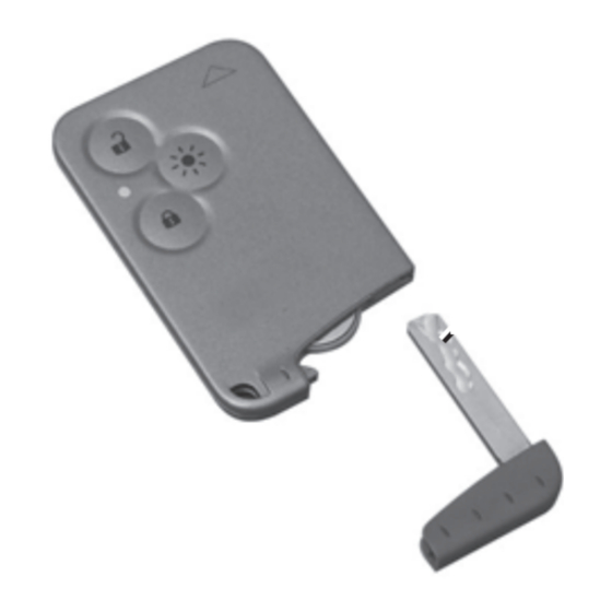
Page 228: Renault Card: Battery
Pull firmly on emergency key 1. Replace battery 2 in accordance with the polarity denoted on the emergency key (check that indicator light 3 lights The batteries are available from ap- up properly by pressing a button on the proved dealers. - Page 229 BAtterY: troubleshooting to avoid all risk of sparks: – Ensure that any electrical consumers (courtesy lights, etc.) are switched off before disconnecting or recon- necting the battery. – When charging, stop the charger before connecting or disconnecting the battery. – Do not place metal objects on the battery to avoid creating a short cir- cuit between the terminals.
-
Page 230: Connecting A Battery Charger
BAtterY: troubleshooting (continued) connecting a battery charger – When the exterior temperature drops If your vehicle is to be left stationary (in winter), the charge decreases. for a relatively long time, disconnect the battery charger must be com- In winter, only use electrical equip- the battery or have it recharged regu- patible with a battery with a nominal ment which is really necessary. - Page 231 BAtterY: troubleshooting (continued) Starting the vehicle using the Check that there is no contact between leads A and B and that the positive (+) battery from another vehicle lead A is not touching any metal parts If you have to use the battery from an- on the vehicle supplying the current.
-
Page 232: Windscreen Wiper Blades
WInDScreen WIPer BLADeS replacing windscreen wiper Windscreen washer jets rear screen wiper blade 4 blades 1 These can be adjusted using a tool – Lift wiper arm 5 as far as it will go; such as a flat-blade screwdriver. – Lift wiper arm 2; –... -
Page 233: Accessories
AcceSSOrIeS Before fitting an electrical or If you are using an anti-theft electronic device (particu- device, only attach it to the larly for transmitters/receiv- brake pedal. ers: frequency bandwidth, power level, position of the aerial etc.), ensure that it is compatible with your vehicle. -
Page 234: Towing: Breakdown
The speed specified by current legis- lation for towing must always be ob- remove served. If your vehicle is the towing RENAULT card from the vehicle, do not exceed the maximum reader when the vehicle is towing weight for your vehicle (refer being towed. - Page 235 tOWInG: breakdown (continued) towing a vehicle with an automatic transmission: special features With the engine switched off: the gearbox is no longer lubricated. It is preferable to tow this type of vehicle on a trailer or tow it with the front wheels off the ground.
- Page 236 tOWInG: towing equipment Permissible nose weight, maxi- mum permissible towing weight, braked and unbraked: refer to the information on “Weights” in Section 6. Please refer to the manufacturer’s instructions on how to fit and use the bars. Please keep these instructions with the rest of the vehicle documenta- tion.
-
Page 237: Operating Faults
POSSIBLe cAuSeS WHAt tO DO The RENAULT card does not lock or Card battery is flat. Replace the battery. You can still lock/ unlock the doors. unlock and start your vehicle (refer to the information on “Locking/unlocking the... - Page 238 The engine will not start. Starting conditions are not fulfilled. Refer to the information on “Starting/stop- ping the engine” in Section 2. The hands-free RENAULT card Insert the card in the card reader in order to does not work. start the engine.
- Page 239 OPerAtInG FAuLtS (3/5) On the road POSSIBLe cAuSeS WHAt tO DO Vibrations. Tyres not inflated to correct pres- Check the tyre pressures: if this is not the sures, incorrectly balanced or dam- problem, have them checked by an ap- aged. proved dealer.
- Page 240 OPerAtInG FAuLtS (4/5) On the road POSSIBLe cAuSeS WHAt tO DO Steering becomes heavy. Assistance overheating. Consult an approved dealer. The engine overheats. The coolant Engine cooling fan not working. Stop the vehicle, switch off the engine and temperature indicator is in the warn- contact an approved dealer.
- Page 241 OPerAtInG FAuLtS (5/5) electrical equipment POSSIBLe cAuSeS WHAt tO DO The wipers do not work. Wiper blades stuck. Free the blades before using the wipers. Faulty electrical circuit. Consult an approved dealer. The wiper does not stop. Faulty electrical controls. Consult an approved dealer.
- Page 242 5.42...
-
Page 243: Technical Specifications
Section 6: Technical specifications Vehicle identification plates ............Engine identification plates . -
Page 244: Vehicle Identification Plates
VEHICLE IDENTIFICATION pLATEs Quote the manufacturer’s plate 3 GTW (Gross train weight – vehicle (right-hand side) in all correspond- fully loaded, with trailer). ence or when ordering parts. 4 Front axle maximum permissible all-up weight. The presence and location of the in- 5 Rear axle maximum permissible formation depends on the vehicle. -
Page 245: Engine Identification Plates
ENgINE IDENTIFICATION pLATEs Quote the information on the identi- fication plate (or label) in all corre- spondence or when ordering parts. Engine marking A 1 Engine type. 2 Engine suffix. 3 Engine number. -
Page 246: Engine Specifications
ENgINE spECIFICATIONs Versions 2.0 T 2.0 dCi Engine type F4R turbo M9R turbo (see engine plate) Cubic capacity (cc) 1 998 1 998 Type of fuel It is essential that you use unleaded petrol Octane rating of the octane rating stated on the label inside the fuel filler flap. -
Page 247: Weights
WEIgHTs (in kg) The weights indicated for a basic vehicle without options: they vary depending on the your vehicle’s equipment. Consult your approved Dealer. Maximum permissible all-up weight (MMAC) Weights are indicated on the vehicle identification plate (refer to Total train weight (MTR) the information on “Vehicle identification plates”... -
Page 248: Dimensions
DIMENsIONs (in metres) 0.175 0.832 (1) 1.574 0.967 (2) 1.026 2.803 (1) – 2.868 (2) 4.661 (1) – 4.861 (2) Unladen 1.801 (1) 1.819 (2) (1) normal chassis (2) long chassis 1.556 1.894... -
Page 249: Replacement Parts And Repairs
REpLACEMENT pARTs AND REpAIRs Original parts are based on strict specifications and are subject to highly-specialised tests. Therefore, they are of at least the same level of quality as the parts fitted originally. If you always fit genuine replacement parts to your vehicle, you will ensure that it performs well. Furthermore, repairs carried out within the manufacturer’s Network using original parts are guaranteed according to the conditions set out on the reverse of the repair order. -
Page 250: Service Sheets
sERVICE sHEETs (1/6) VIN: .................. Date: Miles (km): Invoice number: Comments/miscellaneous Type of operation: stamp Service □ ........ □ Anticorrosion check: OK □ Not OK* □ *See specific page Date: Miles (km): Invoice number: Comments/miscellaneous Type of operation: stamp Service □ ........ □ Anticorrosion check: OK □ Not OK* □... - Page 251 sERVICE sHEETs (2/6) VIN: .................. Date: Miles (km): Invoice number: Comments/miscellaneous Type of operation: stamp Service □ ........ □ Anticorrosion check: OK □ Not OK* □ *See specific page Date: Miles (km): Invoice number: Comments/miscellaneous Type of operation: stamp Service □ ........ □ Anticorrosion check: OK □ Not OK* □...
- Page 252 sERVICE sHEETs (3/6) VIN: .................. Date: Miles (km): Invoice number: Comments/miscellaneous Type of operation: stamp Service □ ........ □ Anticorrosion check: OK □ Not OK* □ *See specific page Date: Miles (km): Invoice number: Comments/miscellaneous Type of operation: stamp Service □ ........ □ Anticorrosion check: OK □ Not OK* □...
- Page 253 sERVICE sHEETs (4/6) VIN: .................. Date: Miles (km): Invoice number: Comments/miscellaneous Type of operation: stamp Service □ ........ □ Anticorrosion check: OK □ Not OK* □ *See specific page Date: Miles (km): Invoice number: Comments/miscellaneous Type of operation: stamp Service □ ........ □ Anticorrosion check: OK □ Not OK* □...
- Page 254 sERVICE sHEETs (5/6) VIN: .................. Date: Miles (km): Invoice number: Comments/miscellaneous Type of operation: stamp Service □ ........ □ Anticorrosion check: OK □ Not OK* □ *See specific page Date: Miles (km): Invoice number: Comments/miscellaneous Type of operation: stamp Service □ ........ □ Anticorrosion check: OK □ Not OK* □...
- Page 255 sERVICE sHEETs (6/6) VIN: .................. Date: Miles (km): Invoice number: Comments/miscellaneous Type of operation: stamp Service □ ........ □ Anticorrosion check: OK □ Not OK* □ *See specific page Date: Miles (km): Invoice number: Comments/miscellaneous Type of operation: stamp Service □ ........ □ Anticorrosion check: OK □ Not OK* □...
-
Page 256: Anticorrosion Check
ANTICORROsION CHECk (1/5) If the continuation of the warranty is subject to repair, it is indicated below. VIN: ............stamp Corrosion repair operation to be carried out: Date of repair: Repair to be carried out: stamp Date of repair: Repair to be carried out: stamp Date of repair: 6.14... - Page 257 ANTICORROsION CHECk (2/5) If the continuation of the warranty is subject to repair, it is indicated below. VIN: ............stamp Corrosion repair operation to be carried out: Date of repair: Repair to be carried out: stamp Date of repair: Repair to be carried out: stamp Date of repair: 6.15...
- Page 258 ANTICORROsION CHECk (3/5) If the continuation of the warranty is subject to repair, it is indicated below. VIN: ............stamp Corrosion repair operation to be carried out: Date of repair: Repair to be carried out: stamp Date of repair: Repair to be carried out: stamp Date of repair: 6.16...
- Page 259 ANTICORROsION CHECk (4/5) If the continuation of the warranty is subject to repair, it is indicated below. VIN: ............stamp Corrosion repair operation to be carried out: Date of repair: Repair to be carried out: stamp Date of repair: Repair to be carried out: stamp Date of repair: 6.17...
- Page 260 ANTICORROsION CHECk (5/5) If the continuation of the warranty is subject to repair, it is indicated below. VIN: ............stamp Corrosion repair operation to be carried out: Date of repair: Repair to be carried out: stamp Date of repair: Repair to be carried out: stamp Date of repair: 6.18...
-
Page 261: Alphabetical Index
AlphAbeticAl index (1/5) ABS ............... 1.48, 2.23 – 2.24 card emergency key ............1.4 accessories................ 5.33 catalytic converter..............2.6 accessories socket ............1.45 central door locking ..........1.7 → 1.11 additional methods of restraint .....1.23 → 1.26, 1.28 changing a bulb .............5.14 → 5.25 adjusting the seats............. 1.20 changing a wheel.............. -
Page 262: Headlight Beam Adjustment
AlphAbeticAl index (2/5) driving ......2.2 → 2.14, 2.16 → 2.19, 2.21 → 2.40 front seats adjustment ............1.15, 1.19 fuel electric windows ............3.26 → 3.29 advice on fuel economy ........2.12 → 2.14 Electronic Stability Program: ESP ........2.20 filling ..............1.74 → 1.76 emergency brake assist............. 2.25 grade ..............1.74 → 1.76 emergency braking ............2.25 fuel economy ............2.12 → 2.14 emergency spare wheel .......... - Page 263 6.5 functions ............3.47 → 3.50 locking the doors .............1.7 → 1.12 rear view mirrors ............. 1.64 – 1.65 luggage compartment cover ........3.53 – 3.54 RENAULT card luggage retaining net ............3.56 battery ................5.28 use ...............1.2 → 1.8 replacement parts ..............6.7...
- Page 264 AlphAbeticAl index (4/5) reverse gear tool kit ................. 5.7 – 5.8 selecting ............... 2.11 towing roof bars ..............3.57 – 3.58 breakdown ............5.34 – 5.35 roof rack towing a caravan ............5.36 roof bars ............3.57 – 3.58 towing a caravan ..............6.5 running in ................
- Page 265 AlphAbeticAl index (5/5) windscreen washer ..........1.71 → 1.73 wiper blades ..............5.32 wipers ..............1.71 → 1.73 blades ................5.32...
- Page 267 à999105731Rî ö ê ä RENAULT S.A.S. SOCIÉTÉ PAR ACTIONS SIMPLIFIÉE AU CAPITAL DE 533 941 113 € / 13-15, QUAI LE GALLO 92100 BOULOGNE-BILLANCOURT R.C.S. NANTERRE 780 129 987 — SIRET 780 129 987 03591 / TÉL. : 0810 40 50 60...
Need help?
Do you have a question about the Espace and is the answer not in the manual?
Questions and answers
is there a fuse for the heating and ventilation control situated on the drivers door, the led display is not lit. the hot blowers stay on while driving and the blowers stay on after removing the key which drains the battery