Table of Contents
Advertisement
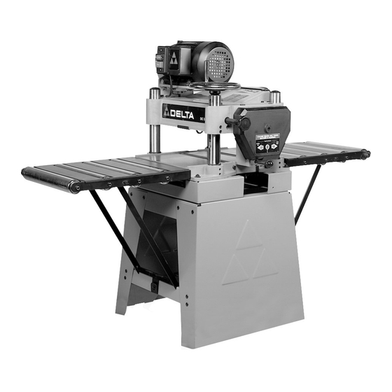
15" Planer
(Model 22-785)
(Model 22-785X)
Shown with Delta
accessory planer stand
and roller extension tables
PART NO. 909593 - 06-07-05
Copyright © 2005 Delta Machinery
To learn more about DELTA MACHINERY
visit our website at: www.deltamachinery.com.
For Parts, Service, Warranty or other Assistance,
1-800-223-7278 (
1-800-463-3582).
please call
In Canada call
Advertisement
Table of Contents

Related Manuals for Delta 22-785


Summary of Contents for Delta 22-785
- Page 1 15" Planer (Model 22-785) (Model 22-785X) Shown with Delta accessory planer stand and roller extension tables PART NO. 909593 - 06-07-05 Copyright © 2005 Delta Machinery To learn more about DELTA MACHINERY visit our website at: www.deltamachinery.com. For Parts, Service, Warranty or other Assistance, 1-800-223-7278 ( 1-800-463-3582).
-
Page 2: Table Of Contents
IMPORTANT SAFETY INSTRUCTIONS ............2 SAFETY GUIDELINES . -
Page 3: Safety Guidelines - Definitions
SAFETY GUIDELINES - DEFINITIONS It is important for you to read and understand this manual. The information it contains relates to protecting YOUR SAFETY and PREVENTING PROBLEMS. The symbols below are used to help you recognize this information. Indicates an imminently hazardous situation which, if not avoided, will result in death or serious injury. Indicates a potentially hazardous situation which, if not avoided, could result in death or serious injury. -
Page 4: General Safety Rules
READ AND UNDERSTAND ALL WARNINGS AND OPERATING INSTRUCTIONS BEFORE USING THIS EQUIPMENT. Failure to follow all instructions listed below, may result in electric shock, fire, and/or serious personal injury or property damage. 1. FOR YOUR OWN SAFETY, READ THE INSTRUCTION MANUAL BEFORE OPERATING THE MACHINE. -
Page 5: Additional Specific Safety Rules
ADDITIONAL SPECIFIC SAFETY RULES FAILURE TO FOLLOW THESE RULES MAY RESULT IN SERIOUS PERSONAL INJURY. DO NOT OPERATE THIS MACHINE until it is completely assembled and installed according to the instructions. A machine incorrectly assembled can cause serious injury. OBTAIN ADVICE from your supervisor, instructor, or another qualified person if you are not thoroughly familiar with the operation of this machine. -
Page 6: Grounding Instructions
POWER CONNECTIONS A separate electrical circuit should be used for your machines. This circuit should not be less than #12 wire and should be protected with a 20 Amp time lag fuse. If an extension cord is used, use only 3-wire extension cords which have 3-prong grounding type plugs and matching receptacle which will accept the machine’s plug. -
Page 7: Extension Cords
FUNCTIONAL DESCRIPTION FOREWORD Delta Models 22-785 and 22-785X are 15" (381mm) Planers with adjustable feed rate for optimum planing under load. They have the following cutting capacities; 15" (381mm) width, 6½" (165mm) thickness and 1/8" (5mm) depth of cut. NOTICE: The photo on the manual cover illustarates the current production model. All other illustrations contained in the manual are representative only and may not depict the actual labeling or accessories included. -
Page 8: Unpacking And Cleaning
1 - Top cover 2 - Cord clamp 3 - Knife setting gage 4 - Open end wrench (14 and 17mm) 5 - Open end wrench (10 and 12mm) 6 - M6x1x16mm hex flange screw (4) - for fastening top cover to machine 7 - Raising and lowering handwheel 8 - Handle for raising and lowering handwheel 9 - Hex wrench (2.5mm) -
Page 9: Lifting The Machine
LIFTING THE MACHINE 1. IMPORTANT: CARE MUST BE TAKEN WHEN LIFTING THE MACHINE ONTO A STAND OR WORKBENCH. THE PLANER IS VERY HEAVY AND A MINIMUM OF FOUR PEOPLE WILL BE REQUIRED TO LIFT THE MACHINE AS FOLLOWS: 2. Raise the cuttinghead (A) Fig. 10, by turning the raising and lowering handwheel (B) clockwise, and insert two 6 or 8 foot long 2 x 4’s (C) between the cuttinghead... -
Page 10: Operation
DUST CHUTE 1. Fasten the top cover and dust chute (A) Fig. 16, to the top of the planer, as shown, using the three M6x16mm screws (B) supplied. IMPORTANT: The dust chute opening (C) must point to the rear as shown. -
Page 11: Feed Speed Control
DEPTH OF CUT ADJUSTMENT The depth of cut on your planer is controlled by raising or lowering the head assembly (A) Fig. 22, which contains the cutterhead and feed rollers. The head assembly (A) moves on four precision ground steel columns, three of which are shown at (B). -
Page 12: Anti-Kickback Fingers
POWER SOURCE. A series of anti-kickback fingers (A) Fig. 27, are provided on the infeed end of the planer, to prevent kickback of the workpiece during the planing operation. These anti- kickback fingers operate by gravity and no adjustment is required. - Page 13 4. Remove the three screws (E) Fig. 34, and remove the chip deflector (F). 5. To check and adjust the knives, proceed as follows: A. Carefully place the knife setting gage (G) Fig. 35, on the cutterhead as shown. B. When the knives are adjusted correctly, the knife (H) Fig.
-
Page 14: Adjusting Height
ADJUSTING HEIGHT OF CHIPBREAKER The chipbreaker extends down around the front of the cutterhead and raises as stock is fed through the planer. The chipbreaker “breaks or curls” the chips as they leave the cutterhead and the bottom edge of the chipbreaker helps hold the stock flat down on the table during the planing operation. - Page 15 ADJUSTING HEIGHT OF INFEED ROLLER The infeed roller is adjusted at the factory at 0.040" below the cutting circle. To check and adjust the height of the infeed roller, proceed as follows: DISCONNECT MACHINE FROM POWER SOURCE. 1. Make sure the knives are adjusted properly as ex- plained under “CHECKING, ADJUSTING AND RE- PLACING KNIVES.”...
-
Page 16: Adjusting Table Rollers
Your planer is supplied with two table rollers (A) Fig. 47, which aid in feeding the stock by reducing friction and turn as the stock is fed through the planer. It is not possible to give exact dimensions on the proper height setting of the table rollers because each type of wood behaves differently. - Page 17 3. Repeat STEPS 2 and 3 on outfeed end of table. 4. If head casting is not parallel to table, tilt planer on its side as shown in Fig. 51. Remove bolt (C) and loosen bolt (D) Fig.
-
Page 18: Machine Use
2. Plane to Thickness – Place the side you just surfaced in STEP 1 face down and feed the board through the planer, plane until this side is flat. Then plane both sides of the board until you are satisfied with the thickness, making thin cuts, alternating sides with each pass. -
Page 19: Service
KEEP MACHINE CLEAN Periodically blow out all air passages with dry compressed air. All plastic parts should be cleaned with a soft damp cloth. NEVER use solvents to clean plastic parts. They could possibly dissolve or otherwise damage the material. Wear ANSI Z87.1 safety glasses while using compressed air. - Page 20 PORTER-CABLE (CENTROS DE SERVICIO DE PORTER-CABLE Parts and Repair Service for Porter-Cable (Obtenga Refaccion de Partes o Servicio para su Herramienta en los Siguientes Centros de Porter-Cable ARIZONA GEORGIA Phoenix 85013-2906 Forest Park 30297 (Atlanta) 4501 N. 7th Ave. 5442 Frontage Road, Phone: (602) 279-6414 Suite 112 Fax: (602) 279-5470...
Need help?
Do you have a question about the 22-785 and is the answer not in the manual?
Questions and answers