Table of Contents
Advertisement
Quick Links
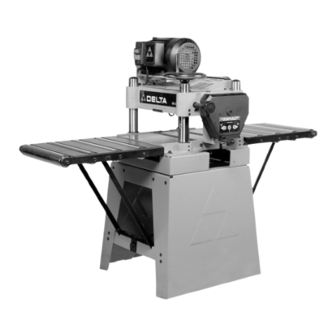
15" Planer
(Model 22-785)
(Model 22-785X)
Shown with Delta
accessory planer stand
and roller extension tables
PART NO. 909593 - 02-26-03
Copyright © 2003 Delta Machinery
To learn more about DELTA MACHINERY
visit our website at: www.deltamachinery.com.
For Parts, Service, Warranty or other Assistance,
1-800-223-7278 (
1-800-463-3582).
please call
In Canada call
Advertisement
Table of Contents

Related Manuals for Delta 22-785


Summary of Contents for Delta 22-785
- Page 1 Shown with Delta accessory planer stand and roller extension tables PART NO. 909593 - 02-26-03 Copyright © 2003 Delta Machinery To learn more about DELTA MACHINERY visit our website at: www.deltamachinery.com. For Parts, Service, Warranty or other Assistance, 1-800-223-7278 ( 1-800-463-3582).
-
Page 2: Safety Guidelines - Definitions
If you have any questions relative to a particular application, DO NOT use the machine until you have first contacted Delta to determine if it can or should be performed on the product. - Page 3 16. USE RECOMMENDED ACCESSORIES. The use of 21. NEVER LEAVE TOOL RUNNING UNATTENDED. accessories and attachments not recommended by Delta TURN POWER OFF. Don’t leave tool until it comes to a may cause hazards or risk of injury to persons.
-
Page 4: Power Connections
POWER CONNECTIONS A separate electrical circuit should be used for your machines. This circuit should not be less than #12 wire and should be protected with a 20 Amp time lag fuse. If an extension cord is used, use only 3-wire extension cords which have 3- prong grounding type plugs and matching receptacle which will accept the machine’s plug. -
Page 5: Extension Cords
FUNCTIONAL DESCRIPTION FOREWORD Delta Models 22-785 and 22-785X are 15" (381mm) Planers with adjustable feed rate for optimum planing under load. They have the following cutting capacities; 15" (381mm) width, 6½" (165mm) thickness and 1/8" (5mm) depth of cut. UNPACKING AND CLEANING Carefully unpack the machine and all loose items from the shipping container(s). - Page 6 PLANER PARTS Your new 15" Planer is shipped complete in one box mounted to a shipping skid. IMPORTANT: The machine is very heavy. Care must be taken when removing the machine from the skid (see the section “LIFTING THE MACHINE”). Remove screw (A) Fig. 2. Remove the re- maining screw from other side of machine in the same manner.
- Page 7 ASSEMBLY FOR YOUR OWN SAFETY, DO NOT CONNECT THE MACHINE TO THE POWER SOURCE UNTIL THE MACHINE IS COMPLETELY ASSEMBLED AND YOU READ AND UNDERSTAND THE ENTIRE INSTRUCTION MANUAL. CUTTINGHEAD RAISING AND LOWERING HANDWHEEL 1. Insert key (A) Fig. 7, into keyway (B) of raising and lowering shaft.
-
Page 8: Operating Controls And Adjustments
ASSEMBLING TOP COVER AND DUST CHUTE 1. Fasten the top cover and dust chute (A) Fig. 16, to the top of the planer, as shown, using the three M6x16mm screws (B) supplied. IMPORTANT: The dust chute opening (C) must point to the rear as shown. Fig. - Page 9 DEPTH OF CUT ADJUSTMENT The depth of cut on your planer is controlled by raising or lowering the head assembly (A) Fig. 22, which contains the cutterhead and feed rollers. The head assembly (A) moves on four precision ground steel columns, three of which are shown at (B).
- Page 10 ANTI-KICKBACK FINGERS WHEN INSPECTING AND CLEANING THE ANTI-KICKBACK FINGERS, MAKE SURE THE MACHINE IS DISCONNECTED FROM THE POWER SOURCE. A series of anti-kickback fingers (A) Fig. 27, are provided on the infeed end of the planer, to prevent kickback of the workpiece during the planing operation.
- Page 11 CHECKING, ADJUSTING AND REPLACING KNIVES To check, adjust or replace the knives, proceed as follows: DISCONNECT MACHINE FROM POWER SOURCE. 1. Remove four screws (A) Fig. 30 and Fig. 31, and remove top cover (B). 2. Loosen two screws (C) Fig. 32, and pivot motor as- Fig.
- Page 12 Fig. 34 Fig. 35 5. If the knives are removed for sharpening, care must be exercised in replacing and resetting them, as follows: A. Remove the knife (M) Fig. 37, locking bar (N), and locking screws (K) from the cutterhead. Repeat this process for the two remaining knives, locking bars, and locking screws.
- Page 13 ADJUSTING HEIGHT OF CHIPBREAKER The chipbreaker extends down around the front of the cutterhead and raises as stock is fed through the planer. The chipbreaker “breaks or curls” the chips as they leave the cutterhead and the bottom edge of the chipbreaker helps hold the stock flat down on the table during the planing operation.
- Page 14 ADJUSTING HEIGHT OF INFEED ROLLER The infeed roller is adjusted at the factory at 0.040" below the cutting circle. To check and adjust the height of the infeed roller, proceed as follows: DISCONNECT MACHINE FROM POWER SOURCE. 1. Make sure the knives are adjusted properly as ex- plained under “CHECKING, ADJUSTING AND RE- PLACING KNIVES.”...
- Page 15 ADJUSTING SPRING TENSION OF INFEED AND OUTFEED ROLLERS The infeed and outfeed rollers are those parts of your planer that feed the stock while it is being planed. The feed rollers are under spring tension and this tension must be sufficient to feed the stock uniformly through the planer without slipping but should not be too tight that it causes damage to the board.
- Page 16 ADJUSTING CUTTINGHEAD PARALLEL TO TABLE The cuttinghead is set parallel to the table at the factory and no further adjustment should be necessary. If your machine is planing a taper, first check to see if the knives are set properly in the cutterhead. Then check to see if the cuttinghead is set parallel to the table as follows: DISCONNECT MACHINE FROM POWER SOURCE.
-
Page 17: Operating Hints
OPERATING HINTS When using your machine, you may want to follow these few simple steps for achieving the best results possible. 1. True Up One Face – Feed one face of the board over a jointer, making thin cuts with each pass, until the entire surface is flat. -
Page 18: Maintenance
LUBRICATION The gear box oil should be changed once a year. Use extreme pressure gear oil, available from Delta in one pint cans (you will need approximately 20 oz.). The gear box drain plug is shown at (A) Fig. 53. The oil fill and level plug is shown at (B) Fig. -
Page 19: Parts, Service Or Warranty Assistance
Two Year Limited Warranty Delta will repair or replace, at its expense and at its option, any Delta machine, machine part, or machine accessory which in normal use has proven to be defective in workmanship or material, provided that the customer returns the product prepaid to a Delta factory service center or authorized service station with proof of purchase of the product within two years and provides Delta with reasonable opportunity to verify the alleged defect by inspection. - Page 20 Delta Distributor, Authorized · Service Center, or Porter-Cable Delta Factory Service Center. If you do not have access to any of these, call 800-223-7278 and you will · be directed to the nearest Porter-Cable Delta Factory Service Center. Las Estaciones de Servicio Autorizadas están ubicadas en muchas grandes ciudades.
Need help?
Do you have a question about the 22-785 and is the answer not in the manual?
Questions and answers