Table of Contents
Advertisement
Advertisement
Table of Contents

Related Manuals for Delta 22-470


Summary of Contents for Delta 22-470
- Page 1 24" Planer (Model 22-470, Three Phase) PART NO. 1342457 06-03-05 Copyright © 2005 Delta Machinery To learn more about DELTA MACHINERY visit our website at: www.deltamachinery.com. For Parts, Service, Warranty or other Assistance, 1-800-223-7278 ( 1-800-463-3582). please call In Canada call...
-
Page 2: Table Of Contents
IMPORTANT SAFETY INSTRUCTIONS ............2 SAFETY GUIDELINES . -
Page 3: Safety Guidelines - Definitions
SAFETY GUIDELINES - DEFINITIONS It is important for you to read and understand this manual. The information it contains relates to protect- ing YOUR SAFETY and PREVENTING PROBLEMS. The symbols below are used to help you recognize this information. Indicates an imminently hazardous situation which, if not avoided, will result in death or serious injury. Indicates a potentially hazardous situation which, if not avoided, could result in death or serious injury. -
Page 4: General Safety Rules
READ AND UNDERSTAND ALL WARNINGS AND OPERATING INSTRUCTIONS BEFORE USING THIS EQUIPMENT. Failure to follow all instructions listed below, may result in electric shock, fire, and/or serious personal injury or property damage. 1. FOR YOUR OWN SAFETY, READ THE INSTRUCTION MANUAL BEFORE OPERATING THE MACHINE. -
Page 5: Additional Specific Safety Rules
ADDITIONAL SPECIFIC SAFETY RULES FAILURE TO FOLLOW THESE RULES MAY RESULT IN SERIOUS INJURY. DO NOT OPERATE THIS MACHINE until it is completely assembled and installed according to the instructions. A machine incorrectly assembled can cause serious injury. OBTAIN ADVICE from your supervisor, instructor, or another qualified person if you are not thor- oughly familiar with the operation of this machine. -
Page 6: Power Connections
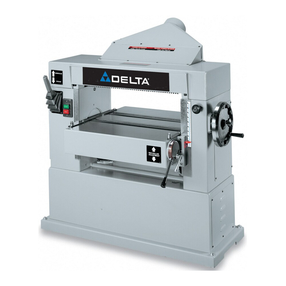
FUNCTIONAL DESCRIPTION FOREWORD The Delta Indusrial Model 22-470 is a 24" Planer with a 7 ation with an LVC magnetic starter and automatic reset overload protection; 3-knife cutterhead, sectional serrated infeed roll, double bed rolls and polyurethane outfeed roll, sectional chipbreakers, dust chute, knife-setting gage and wrench. -
Page 7: Carton Contents
The 22-470 planer is shipped complete in one container mounted to a shipping skid. Remove the wooden crate from around the machine. The planer is shipped with the motor, motor pulleys and belts assembled to the machine. Fig. 2, illustrates the loose items supplied with the machine. -
Page 8: Assembly
NOTE: The other lifting lug is located at the rear and the opposite end of the machine. Carefully remove the planer from the shipping skid. Thread handle assembly (A) Fig. 3, into handwheel (B) and tighten locknut (C). - Page 9 Fig. 7 ASSEMBLING DUST HOOD A dust hood with a 5-inchopening is supplied with your machine and is to be used when connecting the planer to a dust collector or a central dust collection system. Position dust hood (A) Fig. 8, against the rear of the machine and on top of cutterhead guard (B). Align the holes and fasten the dust hood (A) Fig.
-
Page 10: Electrical Connections
ELECTRICAL CONNECTIONS The planer comes wired for 220 volt operation, but it can be wired for 440 volts. Before connecting your machine to an electrical power system, make certain the motor rating agrees with the electrical system it is to be con- nected to. -
Page 11: Operation
OPERATIONAL CONTROLS AND ADJUSTMENTS STARTING AND STOPPING THE PLANER 1. The power switch (A) Fig. 13 is located on the front of the planer. To turn the machine on, push the “START” button. 2. To turn the machine “OFF”, push the stop button (B). - Page 12 FEED ROLLER SPEEDS Your planer is equipped with feed roller speeds of 20 and 30 feet per minute depending on belt placement on the pulleys. As a rule, a faster feed rate is used for gen- eral planing operations, while a slower feed rate (because it provides more cuts per inch of stock) gives a finer and smoother finish to the workpiece.
-
Page 13: Table Rollers
(C) Fig. 20, for quick reference. TABLE ROLLERS Your planer is supplied with two table rollers (A) Fig. 21, which aid in feeding the stock by reducing friction be- tween the stock and the table and rotate as the stock is fed through the planer. - Page 14 CHECKING AND ADJUSTING TABLE ROLLER HEIGHT It is not possible to give exact dimensions on the prop- er height setting of the table rollers because each type of wood has different behavioral patterns. As a general rule, when planing rough stock, the table rollers should be set high (.003 to .005 ) above the table surface.
-
Page 15: Anti-Kickback Fingers
ANTI-KICKBACK FINGERS A series of anti-kickback fingers (A) Fig. 27, are provided on the infeed end of the planer to prevent kickback of the workpiece during planing operations. These anti-kickback fingers operate by gravity and no adjustment is required. It... - Page 16 3. Loosen and tighten two adjustment nuts (C) Fig. 29, to move motor plate up or down as necessary to increase or decrease drive belt tension.Tighten both adjustment nuts (C) against plate (D) Fig. 29, after adjustment is made. 4. Close both side panels. CHECKING AND ADJUSTING FEED ROLLER BELT TENSION Proper tension on the feed roller belt is obtained when...
- Page 17 CHECKING, RESETTING AND REPLACING KNIVES When checking, resetting and replacing knives, proceed as follows: DISCONNECT THE MACHINE FROM THE POWER SOURCE. 2. Remove locking screw and raise top cover (A) Fig. 33, to expose cutterhead (B). 3. Carefully place knife setting gage (C) Figs. 34 and 35, so the gage is positioned on the radiused section of cutterhead (B).
- Page 18 The chipbreakers will rise as stock is fed through the planer and “breaks or curls” the wood chips. The bot- tom of the chipbreakers must be parallel to the knives and set .040 below the cutting circle.
- Page 19 4. Move gage block (B) Fig. 39, directly under chipbreakers (A) as shown. The bottom of chipbreakers (A) Fig. 39, should just touch gage block (B). 5. If an adjustment to the chipbreakers is necessary, loosen two hex nuts (E) Fig. 37, and turn adjustment screws (F) until chipbreakers (A) touch gage block (B) at both sides of the table.
- Page 20 7. Tighten locknuts (E) Fig. 45 after adjustments are com- pleted. ADJUSTING INFEED ROLLER The infeed roller feeds the stock into the planer while the stock is being surfaced. The infeed roller must be posi- tioned uniformly across the planer and .040” below the cutting circle to feed the stock without slipping.
-
Page 21: Leveling The Table
4. Place gage block (A) Fig. 47, under infeed roller (D). The bottom of roller (D) should just touch gage block (A). 5. If an adjustment is necessary, loosen locknut (E) Fig. 48, and turn adjustment screw (F) until the infeed roller just touches the top of gage block (A). -
Page 22: Adjusting Table Gibs
The table height scale indicates the distance the table is from the cutting circle (depth of cut). To check and adjust the pointer, proceed as follows: 1. Run a piece of wood through the planer and stop the machine. 2. Measure the thickness of the planed end of the stock as shown in Fig. -
Page 23: Machine Use
2. Plane to Thickness – Place the side you planed in STEP 1 face down and feed the board through the planer. Plane until this side is flat, then plane both sides of the board until you are satisfied with the thickness. Make thin cuts, and alternate sides with each pass. -
Page 24: Service
PARTS, SERVICE OR WARRANTY ASSISTANCE All Delta Machines and accessories are manufactured to high quality standards and are serviced by a network • of Porter-Cable Delta Factory Service Centers and Delta Authorized Service Stations. To obtain additional information regarding your Delta quality product or to obtain parts, service, warranty assistance, or the loca- tion of the nearest service outlet, please call 1-800-223-7278 (In Canada call 1-800-463-3582). -
Page 25: Warranty
WARRANTY Two Year Limited New Product Warranty Delta will repair or replace, at its expense and at its option, any new Delta machine, machine part, or machine accessory which in normal use has proven to be defective in workmanship or material, provided that the customer returns the prod- uct prepaid to a Delta factory service center or authorized service station with proof of purchase of the product within two years and provides Delta with reasonable opportunity to verify the alleged defect by inspection. - Page 26 NOTES...
- Page 27 NOTES...
- Page 28 PORTER-CABLE (CENTROS DE SERVICIO DE PORTER-CABLE Parts and Repair Service for Porter-Cable (Obtenga Refaccion de Partes o Servicio para su Herramienta en los Siguientes Centros de Porter-Cable ARIZONA GEORGIA Phoenix 85013-2906 Forest Park 30297 (Atlanta) 4501 N. 7th Ave. 5442 Frontage Road, Phone: (602) 279-6414 Suite 112 Fax: (602) 279-5470...
Need help?
Do you have a question about the 22-470 and is the answer not in the manual?
Questions and answers