Table of Contents
Advertisement
Quick Links
Download this manual
See also:
Setup Manual
Advertisement
Table of Contents

Related Manuals for Apogee Mini-DAC


Summary of Contents for Apogee Mini-DAC
- Page 1 2-Channel 24 bit/192kHz D/A Converter (with optional USB) User’s Guide v1.0 - June 2003...
- Page 3 2-Channel 24 bit/192kHz D/A Converter (with optional USB) User’s Guide v1.0 - June 2003...
-
Page 4: Fcc Warning
Copyright Notice The Apogee Mini-DAC is a computer-based device, and as such contains and uses software in ROMs. This software, and all related documentation, including this User’s Guide contain proprietary informa- tion which is protected by copyright laws. -
Page 5: Service Information
This warranty is void if Apogee determines, in its sole business judgment, the defect to be the result of abuse, neglect, alteration or attempted repair by unauthorized personnel. -
Page 6: Declarations Of Conformity
• 73/23/EEC – Low Voltage Directive • 89/336/EEC – EMC Directive Declaration of Conformity – Japan Apogee Electronics Corporation hereby declares that the Mini-DAC, to which this declaration relates, is in material conformity with the VCCI Class A standard. Declaration of Conformity – Australia Apogee Electronics Corporation hereby declares that the Mini-DAC is in material conformity with AN/NZS stan- dard requirements. - Page 7 The serial number is located on the rear panel of the unit. We suggest you record the serial number in the space provided below. Refer to it whenever you call an authorized Apogee Electronics repair facility or the manufacturer. Please be sure to return your completed warranty card immediately! Mini-DAC Serial No.
-
Page 9: Table Of Contents
User’s Guide Table of Contents Introduction .....................2 ..............2 INCLUDED ACCESSORIES ..............2 OPTIONAL ACCESSORIES Getting Started Quickly ................3 ................3 CONNECTING POWER ...................3 QUICKSTART Navigating the Front Panel ..............4-5 ..............4 SAMPLE RATE INDICATORS ..................4 INPUT SELECT ................5 SIGNAL INDICATORS .................5 LOCK INDICATORS ..................5 POWER SWITCH LEVEL... -
Page 10: Introduction
• The Mini-DAC accepts AES, S/PDIF, Optical and USB digital inputs in a wide range of formats, at sample rates up to 192kHz. • Apogee’s Dual-stage clock ensures almost total immunity to jitter at the input stage. • Monitoring facilities such as the front panel Level control, the Output activation matrix, and a powerful, wide- bandwidth headphone output make the Mini-DAC the complete monitoring solution for the Digital Audio Workstation-based studio. -
Page 11: Getting Started Quickly
INPUT SELECT knob to S/PDIF CX. The W(ide) The musical note indicates and N(arrow) LOCK LEDs and the 44.1Khz SAMPLE RATE LED in-depth explanations. should illuminate. 5) Adjust the LEVEL knob for a comfortable listening level. APOGEE ELECTRONICS... -
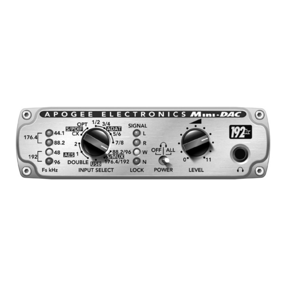
Page 12: Navigating The Front Panel
8) S/MUX 88.2/96 - input is accepted from the Optical connector and treated as S/MUX format at 88.9/96 kHz; only channels 1/2 may be selected as Mini-DAC’s input 9) S/MUX 176.4/192 - input is accepted from the Optical connector and treated as format at 176.4/192 kHz. APOGEE ELECTRONICS... -
Page 13: Signal Indicators
1/8” Output (1/8” OUT Output On Output On jumper on FIX) Fixed Output Level Fixed Output Level FIGURE 1 For more information on configuration of the XLR and 1/8” Outputs, see the section of this manual entitled “INTERNAL ADJUSTMENTS”. APOGEE ELECTRONICS... -
Page 14: Connections On The Rear Panel
LINE OUT – This 1/8” stereo connector provides an unbalanced analog output at a maximum output level of +7 dBV, for use with –10dBV equipment or as a second headphone output. ANALOG OUT – These XLR connectors provide balanced analog outputs with a maximum output level of +24 dBu. APOGEE ELECTRONICS... -
Page 15: Working With Usb
USB cable and driver, as depicted in FIGURE 2. Remember that any device with a digital output may be connected as shown: an Apogee Rosetta or Trak2 A-to-D converter, a CD player or even another DAW. - Page 16 AS WELL AS the USB output. The Mini-DAC’s sample rate is determined by the incoming signal and the INPUT SELECT knob, while the USB output is sample-rate converted to the rate determined by the Host USB device. Digital-Thru-Mode: INPUT SELECT set to any AES , S/PDIF, or Optical setting FIGURE 3 APOGEE ELECTRONICS...
-
Page 17: Using The Minidac With Macintosh Computers
OS 9.1 and later – ASIO For best latency performance and 24-bit recording under Mac OS 9, it’s necessary to download the MiniDAC ASIO driver from the Apogee website at www.apogeedigital.com/usb. Download the driver and decompress the files using Aladdin Systems Stuffit Expander utility. -
Page 18: Os X
OS 9.1 and later – ASIO (continued) Configure the ASIO compatible application for use with the Apogee Mini-DAC ASIO Driver. For example, in Emagic Logic follow these steps: Go to the Preferences>Audio Driver page, expand the ASIO properties and select the Apogee MiniDAC ASIO Driver. -
Page 19: Using The Minidac With Windows Computers
Working with USB - continued Windows – General Regardless of the OS version, it is highly recommended to install the Apogee MiniDAC USB. Please consult the following application notes specific to each Windows version for important warnings and other information. -
Page 20: About Digital Audio Formats
Double Wire format can carry only 1 channel of audio per connection, uses XLR connectors, is used only with sample rates between 88.2 and 192 kHz, and transmits data at half the sample rate – i.e., bits travel at 48kHz when transmitting a 96kHz digital audio signal. APOGEE ELECTRONICS... -
Page 21: Internal Adjustments
When jumpers are installed between the two pins labeled VAR, the output level is controlled by the Front Panel LEVEL knob (factory default). • When jumpers are installed between the two pins labeled FIX, the output level is fixed at a maximum output level of +7 dBV. APOGEE ELECTRONICS... -
Page 22: Installing The Usb Option Card
Mini-DAC rear panel, screws in the locations indicated. Re-install the ensure that connector pins under the card are Mini-DAC Top Cover. properly aligned (indicated at right), and gently press the Option Card into place. APOGEE ELECTRONICS... -
Page 23: Specifications
• Inputs include AES (single & double wide), Optical (ADAT, S/MUX & S/PDIF) coax, & USB • Analog Output level control for direct connection of powered monitors • Low-current, low-voltage -ideal for location/ENG • Digital thru mode adds USB functionality to any digital device including Apogeeʼs Mini-Me, Trak2 and Rosetta Inputs: Specs: •... - Page 24 Mini-DAC USER’S GUIDE - v.1.0 - June 2003 Text conceived and delivered by: Roger Robindore Graphics and product illustration by: Sean McArthur...
Need help?
Do you have a question about the Mini-DAC and is the answer not in the manual?
Questions and answers