Table of Contents
Advertisement
Advertisement
Table of Contents

Related Manuals for Apogee ROSETTA 200


Summary of Contents for Apogee ROSETTA 200
- Page 1 2-channel 24 bit, 192 kHz, AD/DA Converter User’s Guide v1.0 - October 2004...
- Page 3 2-channel 24 bit, 192 kHz, AD/DA Converter User’s Guide v1.0 - October 2004...
-
Page 4: Fcc Warning
Copyright Notice The Apogee ROSETTA 200 is a computer-based device, and as such contains and uses software in ROMs. This software, and all related documentation, including this User’s Guide contain proprietary information which is protected by copyright laws. -
Page 5: Service Information
This warranty is void if Apogee determines, in its sole business judgment, the defect to be the result of abuse, neglect, alteration or attempted repair by unauthorized personnel. -
Page 6: Declarations Of Conformity
• 73/23/EEC – Low Voltage Directive • 89/336/EEC – EMC Directive Declaration of Conformity – Japan Apogee Electronics Corporation hereby declares that the ROSETTA 200, to which this declaration relates, is in material conformity with the VCCI Class A standard. Declaration of Conformity – Australia Apogee Electronics Corporation hereby declares that the ROSETTA 200 is in material conformity with AN/NZS standard requirements. - Page 7 The serial number is located on the rear panel of the unit. We suggest you record the serial number in the space provided below. Refer to it whenever you call an authorized Apogee Electronics repair facility or the manufacturer. Please be sure to return your com- pleted warranty card immediately! ROSETTA 200 Serial No._________________________________________________...
-
Page 9: Table Of Contents
User’s Guide Table of Contents Introduction ........................2 Signal Flow Diagram ....................2 Getting Started Quickly ....................3 Using this manual ....................3 Connecting Power ....................3 Reset ........................3 Quickstart ......................3 Navigating the Front Panel ..................4-7 About Secondary Parameters ................4 Power Switch ......................4 SAMPLE RATE ......................4 AES FMT ........................4... -
Page 10: Introduction
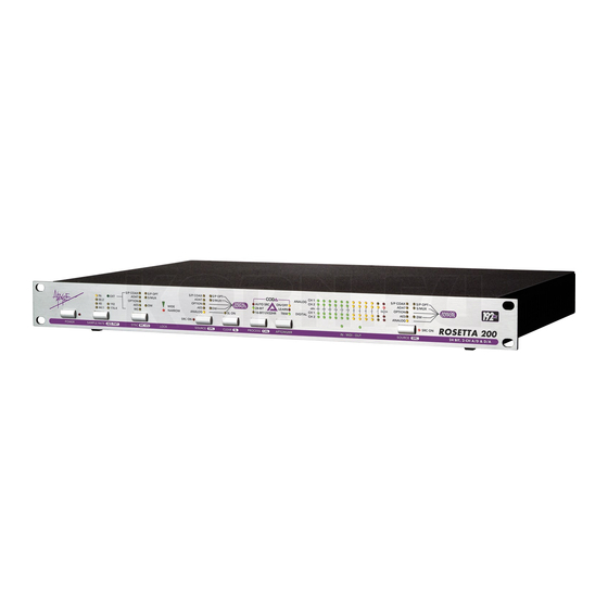
APOGEE ELECTRONICS Introduction Apogee Electronics’ Rosetta 200 is a two channel Analog to Digital and Digital to Analog converter that features the same premium quality signal path as its big brother - the Rosetta-800 - as well as enhanced digital functionality that makes it suitable for a wide variety of applications in the modern digital studio. -
Page 11: Getting Started Quickly
ROSETTA 200 – User’s Guide APOGEE ELECTRONICS Getting Started Quickly USING THIS MANUAL In this manual, “parameters” are defined as the characteristics of operation, such as CLOCK SOURCE or AES format, and are capitalized in this manner : CLOCK SOURCE. -
Page 12: Navigating The Front Panel
ROSETTA 200 – User’s Guide APOGEE ELECTRONICS Navigating the Front Panel About Secondary Parameters - Most front panel buttons control both a primary and secondary parameter; as indicated by the two labels under each button. Secondary parameters are usually accessed by pressing and holding the corresponding button. -
Page 13: Wc I/O
24-BIT/16-BIT/UV22HR – When the unit sample rate is set to a range of 44.1-48k, the bit resolution of all digital outputs may be set to either 24-Bit or 16-Bit/UV22HR. When 16-Bit/UV22HR is selected, Apogee’s proprietary dither signal, UV22HR, is employed to encode 24-bit resolution in a 16-bit signal. -
Page 14: Sample Rate Conversion
Sample Rate Conversion - As the number of digital audio sample rates increases, the necessity for high quality conversion between these rates grows. For the first time on an Apogee product, sample rate conversion is offered on the Rosetta 200. To employ sample rate conversion: 1 Connect the source to one of the Rosetta 200’s digital inputs and set SOURCE (to Digital Outputs) to the... -
Page 15: Aptomizer
5 Select the D/A channel(s) to calibrate, and press the + (CLEAR) or – (SOURCE to Digital Inputs) 15) APTOMIZER – A new Apogee technology developed for the Rosetta 200, APTOMIZER sets A/D and D/A calibration levels by detecting peak level information at the A/D converter and adjusting both analog inputs and outputs for the optimal setting. -
Page 16: Connections On The Rear Panel
ROSETTA 200 – User’s Guide APOGEE ELECTRONICS Connections on the Rear Panel 14 15 L-R ANALOG IN – These female XLR connectors accept balanced analog line inputs, and are adjustable for a maximum level between +2 and +26 dBu. L-R ANALOG OUT – These male XLR connectors provide balanced analog line outputs, and are adjustable a maximum level between +2 and +26 dBu. -
Page 17: Additional Configurations
Additional Configurations Figure 4 MIDI Firmware Update To allow the greatest flexibility in the field, Apogee now employs a firmware update method using stardard Midi protocol. You’ll need the following items to update the firmware of your Apogee device: •... -
Page 18: Power Switch Setting
ROSETTA 200 – User’s Guide APOGEE ELECTRONICS Additional Configurations - continued Power Switch Setting JUMPER P3 DESCRIPTION (as seen from front) When AC power is applied to the input, the unit does not power up immediately; to power on the unit,the POWER button must be pressed. - Page 19 • AES Out: x 2, transformer balanced, XLR connector • S/ PDIF Out: Toslink and Coax • ADAT/SMUX Out: Toslink • WC Out: BNC 75 ohm Due to on-going development Apogee reserves the right to change all information and specifications without notice.
- Page 20 ROSETTA 200 USER’S GUIDE - v1.0 - SEPTEMBER 2004 Text conceived and delivered by: Roger Robindore Graphics and product illustration by: Sean McArthur...
Need help?
Do you have a question about the ROSETTA 200 and is the answer not in the manual?
Questions and answers