Table of Contents
Advertisement
Advertisement
Table of Contents

Subscribe to Our Youtube Channel
Related Manuals for Asus P5KR


Summary of Contents for Asus P5KR
- Page 1 P5KR...
- Page 2 Product warranty or service will not be extended if: (1) the product is repaired, modified or altered, unless such repair, modification of alteration is authorized in writing by ASUS; or (2) the serial number of the product is defaced or missing.
-
Page 3: Table Of Contents
Welcome! ..................1-1 Package contents ................. 1-1 Special features ................1-2 1.3.1 Product highlights ............1-2 1.3.2 ASUS AI Lifestyle features ..........1-4 1.3.3 ASUS Stylish features ............. 1-6 1.3.4 ASUS Intelligent Overclocking features ......1-6 Chapter2:Hardware information Before you proceed ..............2-1 Motherboard overview .............. -
Page 4: Contents
4.1.1 ASUS Update utility ............4-1 4.1.2 Creating a bootable floppy disk ........4-4 4.1.3 ASUS EZ Flash 2 utility ........... 4-5 4.1.4 AFUDOS utility ..............4-6 4.1.5 ASUS CrashFree BIOS 3 utility ........4-8 BIOS setup program ..............4-9 4.2.1... - Page 5 4.6.2 Boot Settings Configuration .......... 4-31 4.6.3 Security ................. 4-32 Tools menu ................. 4-34 4.7.1 ASUS EZ Flash 2 ............4-34 4.7.2 ASUS O.C. Profile ............4-35 Exit menu ..................4-36 Chapter5: Software support Installing an operating system ........... 5-1 Support CD information ..............
- Page 6 Other information ............5-7 Software information ..............5-9 5.3.1 ASUS MyLogo2™ ............5-9 5.3.2 Audio configurations ............5-11 5.3.3 ASUS PC Probe II ............5-15 5.3.4 ASUS AI Suite ............... 5-21 5.3.5 ASUS AI Gear 2 ............5-23 5.3.6 ASUS AI Nap ..............5-24 5.3.7...
-
Page 7: Notices
Notices Federal Communications Commission Statement This device complies with Part 15 of the FCC Rules. Operation is subject to the following two conditions: • This device may not cause harmful interference, and • This device must accept any interference received including interference that may cause undesired operation. -
Page 8: Safety Information
Safety information Electrical safety • To prevent electrical shock hazard, disconnect the power cable from the electrical outlet before relocating the system. • When adding or removing devices to or from the system, ensure that the power cables for the devices are unplugged before the signal cables are connected. -
Page 9: About This Guide
Refer to the following sources for additional information and for product and software updates. ASUS websites The ASUS website provides updated information on ASUS hardware and software products. Refer to the ASUS contact information. Optional documentation Your product package may include optional documentation, such as warranty flyers, that may have been added by your dealer. -
Page 10: Conventions Used In This Guide
Conventions used in this guide To make sure that you perform certain tasks properly, take note of the following symbols used throughout this manual. DANGER/WARNING: Information to prevent injury to yourself when trying to complete a task. CAUTION: Information to prevent damage to the components when trying to complete a task. -
Page 11: P5Kr Specifications Summary
- Supports up to 8 GB system memory * The chipset officially supports the memory frequency up to DDR2 800MHz. Tuned by the ASUS Super Memspeed Technology, this motherboard natively supports up to DDR2 1066MHz. Refer to www.asus.com or this user manual for the Memory QVL (Qualified Vendors Lists). - Page 12 AI Lifestyle Unique ASUS Quiet Thermal Solution: features - ASUS AI Gear 2 - ASUS AI Nap - ASUS Fanless Design: Heat-pipe solution - ASUS Q-Fan 2 ASUS Crystal Sound: - ASUS Noise Filter ASUS EZ DIY: - ASUS Q-Connector - ASUS O.C.
- Page 13 ACPI 2.0a Manageability WfM 2.0, DMI 2.0, WOL by PME, WOR by PME, PXE Support CD contents Drivers ASUS PC Probe II ASUS Update ASUS AI Suite Anti-virus software (OEM version) Form factor ATX form factor: 12 in x 9.6 in (30.5 cm x 24.5 cm) *Specifications are subject to change without notice.
-
Page 15: Chapter1: Product Introduction
This chapter describes the motherboard features and the new technologies it supports. Product introduction... - Page 16 Chapter summary Welcome! ..................1-1 Package contents ................. 1-1 Special features ................1-2 ASUS P5KR...
-
Page 17: Welcome
® The motherboard delivers a host of new features and latest technologies, making it another standout in the long line of ASUS quality motherboards! Before you start installing the motherboard, and hardware devices on it, check the items in your package with the list below. -
Page 18: Special Features
Green ASUS This motherboard and its packaging comply with the European Union’s Restriction on the use of Hazardous Substances (RoHS). This is in line with the ASUS vision of creating environment-friendly and recyclable products/packaging to safeguard consumers’ health while minimizing the impact on the environment. -
Page 19: High Definition Audio
ASUS Super Memspeed Technology To attain top performance, ASUS has managed to break through current FSB and DRAM ratio proportions by utilizing Super Memspeed Technology–the latest technology that provides even more precise overclocking options to unleash the true potential of DDR2 memory. The DDR2 Mode maximizes system performance by eliminating the bottleneck when overclocking both the CPU and memory–... -
Page 20: Asus Ai Lifestyle Features
Q-Fan 2 ASUS Q-Fan 2 technology intelligently adjusts both CPU fan and chassis fan speeds according to system loading to ensure quiet, cool and efficient operation. See pages 4-27 and 5-26 for details. - Page 21 Smart Support CD It provides a checklist to allow the user to see which drivers are already installed, as well as those that aren’t. When using ASUS PC Probe II, you can easily see the critical parts of the computer.
-
Page 22: Asus Stylish Features
See pages 4-17 and 5-25 for details. AI Booster The ASUS AI Booster allows you to overclock the CPU speed in Windows environment without the hassle of booting the BIOS. See page 5-27 for details. -
Page 23: Chapter2:Hardware Information
This chapter lists the hardware setup procedures that you have to perform when installing system components. It includes description of the jumpers and connectors on the motherboard. Hardware information... - Page 24 Chapter summary Before you proceed ..............2-1 Motherboard overview ..............2-2 Central Processing Unit (CPU) ........... 2-6 System memory ................. 2-13 Expansion slots ................2-19 Jumper ..................2-24 Connectors ................. 2-25 ASUS P5KR...
-
Page 25: Before You Proceed
ON, in sleep mode, or in soft-off mode. This is a reminder that you should shut down the system and unplug the power cable before removing or plugging in any motherboard component. The illustration below shows the location of the onboard LED. P5KR SB_PWR Standby Powered P5KR Onboard LED Power ASUS P5KR... -
Page 26: Motherboard Overview
Motherboard overview Before you install the motherboard, study the configuration of your chassis to ensure that the motherboard fits into it. Make sure to unplug the power cord before installing or removing the motherboard. Failure to do so can cause you physical injury and damage motherboard components. -
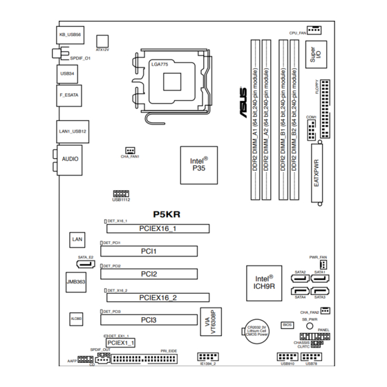
Page 27: Motherboard Layout
SATA3 DET_PCI3 CHA_FAN2 PCI3 ALC883 SB_PWR BIOS CR2032 3V PANEL Lithium Cell CMOS Power DET_EX1_1 PCIEX1_1 CHASSIS CLRTC SPDIF_OUT PRI_EIDE AAFP IE1394_2 USB910 USB78 Refer to 2.7 Connectors for more information about rear panel connectors and internal connectors. ASUS P5KR... -
Page 28: Layout Contents
2.2.4 Layout contents Slots Page DDR2 DIMM slots 2-13 PCI slots 2-21 PCI Express x1 slot 2-21 PCI Express x16 slots 2-21 Jumper Page Clear RTC RAM (3-pin CLRTC) 2-24 Rear panel connectors Page PS/2 keyboard port (purple) 2-25 IEEE 1394a port 2-25 LAN (RJ-45) port 2-25... - Page 29 2-37 • System power LED (2-pin PLED) • Hard disk drive activity LED (2-pin IDE_LED) • System warning speaker (4-pin SPEAKER) • ATX power button/soft-off button (2-pin PWR) • Reset button (2-pin RESET) ASUS Q-connector (system panel) 2-38 ASUS P5KR...
-
Page 30: Central Processing Unit (Cpu)
ASUS will shoulder the cost of repair only if the damage is shipment/transit-related. • Keep the cap after installing the motherboard. ASUS will process Return Merchandise Authorization (RMA) requests only if the motherboard comes with the cap on the LGA775 socket. -
Page 31: Installing The Cpu
This side of the socket box should face you. To prevent damage to the socket pins, do not remove the PnP cap unless you are installing a CPU. Lift the load lever in the direction of the arrow to a 135º angle. ASUS P5KR... - Page 32 Lift the load plate with your thumb and forefinger to a 100º angle (A), then push the PnP cap from the load plate window to remove (B). Load plate Alignment key Position the CPU over the socket, making sure that the gold triangle is on the bottom-left corner of the socket then fit the socket...
-
Page 33: Installing The Cpu Heatsink And Fan
CPU fan connector. Motherboard hole Fastener Narrow end of the groove Make sure to orient each fastener with the narrow end of the groove pointing outward. (The photo shows the groove shaded for emphasis.) ASUS P5KR... - Page 34 Push down two fasteners at a time in a diagonal sequence to secure the heatsink and fan assembly in place. Connect the CPU fan cable to the connector on the motherboard labeled CPU_FAN. CPU_FAN P5KR P5KR CPU fan connector Do not forget to connect the CPU fan connector! Hardware monitoring errors can occur if you fail to plug this connector.
- Page 35 Rotate each fastener counterclockwise. Pull up two fasteners at a time in a diagonal sequence to disengage the heatsink and fan assembly from the motherboard. Carefully remove the heatsink and fan assembly from the motherboard. ASUS P5KR 2-11...
- Page 36 Rotate each fastener clockwise to ensure correct orientation when reinstalling. Narrow end of the groove The narrow end of the groove should point outward after resetting. (The photo shows the groove shaded for emphasis.) Refer to the documentation in the boxed or stand-alone CPU fan package for detailed information on CPU fan installation.
-
Page 37: System Memory
Sockets Channel A DIMM_A1 and DIMM_A2 Channel B DIMM_B1 and DIMM_B2 • This chipset officially supports DDR2-800 MHz. With the ASUS Super Memspeed Technology, this motherboard natively supports up to DDR2-1066 MHz. See the table below. DDR2 1333 1066* 1333... -
Page 38: Memory Configurations
2.4.2 Memory configurations You may install 256 MB, 512 MB, 1 GB, and 2 GB unbuffered non-ECC DDR2 DIMMs into the DIMM sockets. Recommended Memory Configurations Sockets Mode DIMM_A1 DIMM_A2 DIMM_B1 DIMM_B2 – – Populated – Single-Channel Populated – – –... - Page 39 Dual-channel memory configuration. • C*: Supports 4 modules inserted into both the yellow and black slots as two pairs of Dual-channel memory configuration. Visit the ASUS website for the latest DDR2-1066/800/667MHz QVL. ASUS P5KR 2-15...
- Page 40 P5KR Motherboard Qualified Vendors Lists (QVL) DDR2-800 MHz capability DIMM support Size Vendor Chip No. Part No. 512MB KINGSTON K4T51083QC KVR800D2N5/512 • • • 1024MB KINGSTON Heat-Sink Package KHX6400D2LLK2/1GN • • • 1024MB KINGSTON V59C1512804QBF25 KVR800D2N5/1G • • • 256MB Qimonda HYB18T512160BF-25F HYS64T32000HU-25F-B...
- Page 41 TB3D2667C58S • • • 1024MB SMART G64M8XB3ITIX4TUE TB4D2667C58D • • • 2048MB NANYA NT5TU128M8BJ-3C NT2GT64U8HB0JY-3C • • • 512MB NANYA NT5TU64M8BE-3C NT512T64U88B0BY-3C • • • 512MB A3R12E3GEF637BLC5N AL6E8E63B-6E1K • • • 1024MB A3R12E3GEF637BLC5N AL7E8E63B-6E1K • • • ASUS P5KR 2-17...
-
Page 42: Installing A Dimm
2.4.3 Installing a DIMM Unplug the power supply before adding or removing DIMMs or other system components. Failure to do so can cause severe damage to both the motherboard and the components. To install a DIMM: DDR2 DIMM notch Unlock a DIMM socket by pressing the retaining clips outward. -
Page 43: Expansion Slots
IRQ” or that the cards do not need IRQ assignments. Otherwise, conflicts will arise between the two PCI groups, making the system unstable and the card inoperable. Refer to the table on the next page for details. ASUS P5KR 2-19... -
Page 44: Interrupt Assignments
2.5.3 Interrupt assignments Priority Standard function System timer Keyboard controller – Re-direct to IRQ#9 IRQ holder for PCI steering* Communications port (COM1)* IRQ holder for PCI steering* Floppy disk controller IRQ holder for PCI steering* System CMOS/Real Time Clock IRQ holder for PCI steering* IRQ holder for PCI steering* IRQ holder for PCI steering* IRQ holder for PCI steering*... -
Page 45: Pci Slots
2.5.6 Two PCI Express x16 slots This motherboard supports two ATI CrossFire™ PCI Express x16 graphics cards that comply with the PCI Express specifications. The figure shows two graphics cards installed on the PCI Express x16 slots. ASUS P5KR 2-21... - Page 46 We recommend that you install a VGA card on the primary (blue) PCI Express slot, and install any other PCI Express device on the Universal PCI-E slot (black). Primary PCI Express x16 slot The primary PCI Express x16 slot supports PCI Express x16 graphics cards that comply with the PCI Express specifications.
-
Page 47: Ai Slot Detector
When the LEDs light up, turn off the power before reinstalling the devices. The PCIEX16_1 slot (blue) is for a PCIE x16 card. The DET_X16_1 LED lights up despite correct installation when you install a x1, x4, or x8 card to this slot. ASUS P5KR 2-23... -
Page 48: Jumper
Jumper Clear RTC RAM (3-pin CLRTC) This jumper allows you to clear the Real Time Clock (RTC) RAM in CMOS. You can clear the CMOS memory of date, time, and system setup parameters by erasing the CMOS RTC RAM data. The onboard button cell battery powers the RAM data in CMOS, which include system setup information such as system passwords. -
Page 49: Connectors
Side Speaker Out port (gray). This port connects the side speakers in an 8-channel audio configuration. Refer to the audio configuration table on the next page for the function of the audio ports in 2, 4, 6, or 8-channel configuration. ASUS P5KR 2-25... - Page 50 Audio 2, 4, 6, or 8-channel configuration Headset Port 4-channel 6-channel 8-channel 2-channel Light Blue Line In Line In Line In Line In Lime Line Out Front Speaker Out Front Speaker Out Front Speaker Out Pink Mic In Mic In Mic In Mic In Orange...
- Page 51 13. Coaxial S/PDIF Out port. This port connects an external audio output device via a coaxial S/PDIF cable. 14. USB 2.0 ports 5 and 6. These two 4-pin Universal Serial Bus (USB) ports are available for connecting USB 2.0 devices. ASUS P5KR 2-27...
-
Page 52: Internal Connectors
2.7.2 Internal connectors Floppy disk drive connector (34-1 pin FLOPPY) This connector is for the provided floppy disk drive (FDD) signal cable. Insert one end of the cable to this connector, then connect the other end to the signal connector at the back of the floppy disk drive. Pin 5 on the connector is removed to prevent incorrect cable connection when using a FDD cable with a covered Pin 5. - Page 53 If any device jumper is set as “Cable-Select,” make sure all other device jumpers have the same setting. P5KR PRI_EIDE PIN 1 NOTE: Orient the red markings (usually zigzag) on the IDE ribbon cable to PIN 1. P5KR IDE connector ASUS P5KR 2-29...
- Page 54 ICH9R Serial ATA connectors (7-pin SATA1 [red], SATA2 [red], SATA3 [black], SATA4 [black]) These connectors are for the Serial ATA signal cables for Serial ATA hard disk drives. If you installed Serial ATA hard disk drives, you can create a RAID 0, 1, 5, and 10 configuration with the Intel®...
-
Page 55: Serial Ata Hard Disk Drive Connection
SATA cable to the onboard SATA port to avoid mechanical conflict with huge graphics cards. When using hot-plug and NCQ, set the Configure SATA as in the BIOS to [AHCI]. See section 4.3.6 SATA Configuration for details. ASUS P5KR 2-31... - Page 56 ® JMicron JMB363 Serial ATA RAID connector (7-pin SATA_E2) This connector is for a Serial ATA signal cable that supports a Serial ATA hard disk drive. To configure RAID 0, RAID 1, or JBOD, install an internal Serial ATA hard disk drive to this connector and an external Serial ATA drive to the external SATA port.
- Page 57 Never connect a 1394 cable to the USB connectors. Doing so will damage the motherboard! You can connect the front panel USB cable to the ASUS Q-Connector (USB, blue) first, and then install the Q-Connector (USB) to the USB connector onboard if your chassis supports front panel USB ports.
- Page 58 Never connect a USB cable to the IEEE 1394a connector. Doing so will damage the motherboard! You can connect the front panel 1394 cable to the ASUS Q-Connector (1394, red) first, and then install the Q-Connector (1394) to the 1394 connector onboard if your chassis supports front panel 1394 ports.
- Page 59 CHA_FAN2 +12V Rotation P5KR Fan connectors Only the CPU-FAN and CHA-FAN 1-2 connectors support the ASUS Q-FAN 2 feature. 10. Serial port connector (10-1 pin COM1) This connector is for a serial (COM) port. Connect the serial port module cable to this connector, then install the module to a slot opening at the back of the system chassis.
-
Page 60: Chassis Intrusion Connector
11. Chassis intrusion connector (4-1 pin CHASSIS) This connector is for a chassis-mounted intrusion detection sensor or switch. Connect one end of the chassis intrusion sensor or switch cable to this connector. The chassis intrusion sensor or switch sends a high-level signal to this connector when a chassis component is removed or replaced. - Page 61 ® CPU: Intel Pentium Extreme 3.73GHz Memory: 512 MB DDR2 (x4) Graphics card: ASUS EAX1900XT Parallel ATA device: IDE hard disk drive Serial ATA device: SATA hard disk drive (x2) Optical drive: DVD-RW • If you want to use two high-end PCI Express x16 cards, use a PSU with 500W to 600W power or above to ensure the system stability.
-
Page 62: System Panel Connector
14. System panel connector (20-8 pin PANEL) This connector supports several chassis-mounted functions. PLED SPEAKER PANEL P5KR RESET IDE_LED PWRSW Requires an ATX power supply. P5KR System panel connector • System power LED (2-pin PLED) This 2-pin connector is for the system power LED. Connect the chassis power LED cable to this connector. - Page 63 Q-Connector (system panel) You can use ASUS Q-Connector to connect / disconnect chassis front panel cables by only a few steps. Directions below shows how to install ASUS Q- Connector. Step1. Connect correct front panel to ASUS Q- Connector first. You can refer to the marking on Q-Connector itself to know the detail pin definition.
- Page 64 2-40 Chapter 2: Hardware information...
-
Page 65: Chapter3: Powering Up
This chapter describes the power up sequence, the vocal POST messages, and ways of shutting down the system. Powering up... - Page 66 Chapter summary Starting up for the first time ............3-1 Turning off the computer ............. 3-2 ASUS P5KR...
-
Page 67: Starting Up For The First Time
One continuous beep followed by three No VGA detected short beeps One continuous beep followed by four Hardware component failure short beeps At power on, hold down the <Delete> key to enter the BIOS Setup. Follow the instructions in Chapter 4. ASUS P5KR... -
Page 68: Turning Off The Computer
Turning off the computer 3.2.1 Using the OS shut down function ® If you are using Windows Click the Start button then select Turn Off Computer. Click the Turn Off button to shut down the computer. ® The power supply should turn off after Windows shuts down. -
Page 69: Chapter4: Bios Setup
This chapter tells how to change the system settings through the BIOS Setup menus. Detailed descriptions of the BIOS parameters are also provided. BIOS setup... - Page 70 Chapter summary Managing and updating your BIOS ..........4-1 BIOS setup program ..............4-9 Main menu .................. 4-12 Advanced menu ................. 4-16 Power menu ................4-25 Boot menu .................. 4-29 Tools menu ................. 4-33 Exit menu ..................4-35 ASUS P5KR...
-
Page 71: Managing And Updating Your Bios
ASUS Update (Updates the BIOS in Windows environment.) ® ASUS EZ Flash 2 (Updates the BIOS using a floppy disk or USB flash disk.) ASUS AFUDOS (Updates the BIOS using a bootable floppy disk.) ASUS CrashFree BIOS 3 (Updates the BIOS using a bootable floppy disk, USB flash disk or the motherboard support CD when the BIOS file fails or gets corrupted.) - Page 72 To update the BIOS through the Internet: Launch the ASUS Update utility from the Windows desktop by clicking Start ® > Programs > ASUS > ASUSUpdate > ASUSUpdate. The ASUS Update main window appears. Select Update BIOS from the Select the ASUS FTP site nearest...
- Page 73 To update the BIOS through a BIOS file: Launch the ASUS Update utility from the Windows desktop by clicking Start ® > Programs > ASUS > ASUSUpdate > ASUSUpdate. The ASUS Update main window appears. Select Update BIOS from a file option from the drop-down menu, then click Next.
-
Page 74: Creating A Bootable Floppy Disk
4.1.2 Creating a bootable floppy disk Do either one of the following to create a bootable floppy disk. DOS environment a. Insert a 1.44MB floppy disk into the drive. b. At the DOS prompt, type format A:/S then press <Enter>. Windows XP environment ®... -
Page 75: Asus Ez Flash 2 Utility
4.1.3 ASUS EZ Flash 2 utility The ASUS EZ Flash 2 feature allows you to update the BIOS without having to go through the long process of booting from a floppy disk and using a DOS-based utility. The EZ Flash 2 utility is built-in the BIOS chip so it is accessible by pressing <Alt>... -
Page 76: Afudos Utility
Updating the BIOS file To update the BIOS file using the AFUDOS utility: Visit the ASUS website (www.asus.com) and download the latest BIOS file for the motherboard. Save the BIOS file to a bootable floppy disk. Chapter 4: BIOS setup... - Page 77 A:\>afudos /iP5KR.ROM The utility verifies the file and starts updating the BIOS. A:\>afudos /iP5KR.ROM AMI Firmware Update Utility - Version 1.19(ASUS V2.07(03.11.24BB)) Copyright (C) 2002 American Megatrends, Inc. All rights reserved. WARNING!! Do not turn off power during flash BIOS Reading file ..
-
Page 78: Asus Crashfree Bios 3 Utility
4.1.5 ASUS CrashFree BIOS 3 utility The ASUS CrashFree BIOS 3 is an auto recovery tool that allows you to restore the BIOS file when it fails or gets corrupted during the updating process. You can update a corrupted BIOS file using the motherboard support CD, the floppy disk, or the USB flash disk that contains the updated BIOS file. -
Page 79: Bios Setup Program
The BIOS setup screens shown in this section are for reference purposes only, and may not exactly match what you see on your screen. • Visit the ASUS website (www.asus.com) to download the latest BIOS file for this motherboard. ASUS P5KR... -
Page 80: Bios Menu Screen
4.2.1 BIOS menu screen Menu items Menu bar Configuration fields General help BIOS SETUP UTILITY Main Advanced Power Boot Tools Exit Use [ENTER], [TAB] or System Time [10:55:25] [SHIFT-TAB] to select System Date [Fri 03/09/2007] a field. Legacy Diskette A [1.44M, 3.5 in] Use [+] or [-] to configure system Time. -
Page 81: Menu Items
Up/Down arrow keys or <Page Up> /<Page Down> keys to display the other items on the screen. 4.2.9 General help Pop-up window At the top right corner of the menu screen Scroll bar is a brief description of the selected item. ASUS P5KR 4-11... -
Page 82: Main Menu
Main menu When you enter the BIOS Setup program, the Main menu screen appears, giving you an overview of the basic system information. Refer to section 4.2.1 BIOS menu screen for information on the menu screen items and how to navigate through them. BIOS SETUP UTILITY Main Advanced... -
Page 83: Sata 1~4
When set to [Disabled], the data transfer from and to the device occurs one sector at a time. Configuration options: [Disabled] [Auto] PIO Mode [Auto] Selects the PIO mode. Configuration options: [Auto] [0] [1] [2] [3] [4] ASUS P5KR 4-13... -
Page 84: Sata Configuration
DMA Mode [Auto] Selects the DMA mode. Configuration options: [Auto] [SWDMA0] [SWDMA1] [SWDMA2] [MWDMA0] [MWDMA1] [MWDMA2] [UDMA0] [UDMA1] [UDMA2] [UDMA3] [UDMA4] [UDMA5] SMART Monitoring [Auto] Sets the Smart Monitoring, Analysis, and Reporting Technology. Configuration options: [Auto] [Disabled] [Enabled] 32Bit Data Transfer [Enabled] Enables or disables 32-bit data transfer. -
Page 85: Ahci Configuration
S e l e c t t h e t y p e o f devices connected to AHCI Port1 the system. Device :Not Detected SATA Port1 [Auto] SATA Port1 [Auto] Allows you to select the type of device connected to the system. Configuration options: [Auto] [Not Installed] ASUS P5KR 4-15... -
Page 86: System Information
4.3.8 System Information This menu gives you an overview of the general system specifications. The BIOS automatically detects the items in this menu. BIOS SETUP UTILITY Main AMIBIOS Version : 0102 Build Date : 07/04/07 Processor Type : Intel(R) Core(TM)2 Duo CPU @ 3.00GHz Speed : 3000 MHz Count... -
Page 87: Advanced Menu
Loads the optimal settings for the system. Standard Loads the standard settings for the system. N.O.S. The ASUS Non-delay Overclocking System feature intelligently determines the system load and automatically boosts the performance for the most demanding tasks. ASUS P5KR 4-17... - Page 88 Some of the following items appear when you set AI Overclocking to [Manual] or [N.O.S.]. The items vary depending on which option you select. N.O.S. Mode [Auto] Allows you to set the Non-delay Overclocking System mode. Configuration options: [Auto] [Standard] [Sensitive] [Heavy Load] CPU Ratio Control [Auto] Configuration options: [Auto] [Manual] The following item appears when the CPU Ratio Control item is set to...
- Page 89 Transaction Booster [Disabled] Configuration options: [Auto] [Disabled] [Enabled] Clock Over-Charging Mode [Auto] Configuration options: [Auto] [0.70V] [0.80V] [0.90V] [1.00V] CPU Spread Spectrum [Auto] Allows you to enable or disable the CPU spread spectrum. Configuration options: [Auto] [Disabled] ASUS P5KR 4-19...
- Page 90 PCIE Spread Spectrum [Auto] Allows you to enable or disable the PCIE spread spectrum. Configuration options: [Auto] [Disabled] CPU Voltage [Auto] Allows you to select the CPU voltage. Configuration options: [Auto] [1.7000V] [1.6875V] [1.6750V] [1.6625V] [1.6500V] [1.6375V] [1.6250V] [1.6125V] [1.6000V] [1.5875V] [1.5750V] [1.5625V] [1.5500V] [1.5375V] [1.5250V] [1.5125V] [1.5000V] [1.4875V] [1.4750V] [1.4625V] [1.4500V] [1.4375V] [1.4250V] [1.4125V] [1.4000V] [1.3875V] [1.3750V] [1.3625V] [1.3500V] [1.3375V] [1.3250V] [1.3125V] [1.3000V]...
-
Page 91: Usb Configuration
Configuration options: [Disabled] [Enabled] Port 64/60 Emulation [Disabled] Allows you to enable or disable the I/O port 60h/64h emulation support. This item should be enabled for the complete USB keyboard legacy support for non-USB aware OSes. Configuration options: [Disabled] [Enabled] ASUS P5KR 4-21... -
Page 92: Cpu Configuration
Legacy USB Support [Auto] Allows you to enable or disable support for legacy USB devices. Setting to [Auto] allows the system to detect the presence of USB devices at startup. If detected, the USB controller legacy mode is enabled. If no USB device is detected, the legacy USB support is disabled. -
Page 93: Chipset
North Bridge Chipset Configuration ENABLE: Allow remapping of Memory Remap Feature [Enabled] overlapped PCI memory Initiate Graphic Adapter [PEG/PCI] above the total PEG Port Control [Auto] physical memory. PEG Port Force x1 [Disabled] DISABLE: Do not allow remapping of memory. ASUS P5KR 4-23... -
Page 94: Onboard Devices Configuration
Memory Remap Feature [Enabled] Allows you to enabled or disable the remapping of the overlapped PCI memory above the total physical memory. Enable this option only when you install 64-bit operating system. Configuration options: [Disabled] [Enabled] Initiate Graphic Adapter [PEG/PCI] Allows you to decide which graphics controller to use as the primary boot device. -
Page 95: Pci Pnp
When set to [No], BIOS configures all the devices in the system. When set to [Yes] and if you install a Plug and Play operating system, the operating system configures the Plug and Play devices not required for boot. Configuration options: [No] [Yes] ASUS P5KR 4-25... -
Page 96: Power Menu
Power menu The Power menu items allow you to change the settings for the Advanced Power Management (APM). Select an item then press <Enter> to display the configuration options. BIOS SETUP UTILITY Main Advanced Power Boot Tools Exit Select the ACPI state Suspend Mode [Auto] used for System... -
Page 97: Apm Configuration
Allows you to enable or disable the PME to wake up from S5 by PCI devices. Configuration options: [Disabled] [Enabled] Power On By PCIE Devices [Disabled] Allows you to enable or disable the PCIE devices to generate a wake event. Configuration options: [Disabled] [Enabled] ASUS P5KR 4-27... -
Page 98: Hardware Monitor
Power On By PS/2 Keyboard [Disabled] Allows you to disable the Power On by PS/2 keyboard function or set specific keys on the PS/2 keyboard to turn on the system. This feature requires an ATX power supply that provides at least 1A on the +5VSB lead. Configuration options: [Disabled] [Space Bar] [Ctrl-Esc] [Power Key] 4.5.6 Hardware Monitor... - Page 99 N/A. Vcore Voltage, 3.3V Voltage, 5V Voltage, 12V Voltage The onboard hardware monitor automatically detects the voltage output through the onboard voltage regulators. Select [Ignored] if you do not want to detect this item. ASUS P5KR 4-29...
-
Page 100: Boot Menu
Boot menu The Boot menu items allow you to change the system boot options. Select an item then press <Enter> to display the sub-menu. BIOS SETUP UTILITY Main Advanced Power Boot Tools Exit Specifies the Boot Device Priority Boot Device Priority sequence. -
Page 101: Boot Settings Configuration
Configuration options: [Disabled] [Enabled] Full Screen Logo [Enabled] This allows you to enable or disable the full screen logo display feature. Configuration options: [Disabled] [Enabled] Set this item to [Enabled] to use the ASUS MyLogo3 feature. ™ AddOn ROM Display Mode [Force BIOS] Sets the display mode for option ROM. -
Page 102: Security
4.6.3 Security The Security menu items allow you to change the system security settings. Select an item then press <Enter> to display the configuration options. BIOS SETUP UTILITY Boot <Enter> to change Security Settings password. <Enter> again to Supervisor Password :Not Installed disabled password. -
Page 103: Change User Password
Password Check [Setup] When set to [Setup], BIOS checks for user password when accessing the Setup utility. When set to [Always], BIOS checks for user password both when accessing Setup and booting the system. Configuration options: [Setup] [Always] ASUS P5KR 4-33... -
Page 104: Tools Menu
4.7.1 ASUS EZ Flash 2 Allows you to run ASUS EZ Flash 2. When you press <Enter>, a confirmation message appears. Use the left/right arrow key to select between [Yes] or [No], then press <Enter> to confirm your choice. Please see section 4.1.3 for details. -
Page 105: Asus O.c. Profile
4.7.2 ASUS O.C. Profile This item allows you to store or load multiple BIOS settings. BIOS SETUP UTILITY Tools O.C. PROFILE Configuration Save to Profile 1 O.C. Profile 1 Status :Not Installed O.C. Profile 2 Status :Not Installed Save to Profile 1... -
Page 106: Exit Menu
Exit menu The Exit menu items allow you to load the optimal or failsafe default values for the BIOS items, and save or discard your changes to the BIOS items. BIOS SETUP UTILITY Main Advanced Power Boot Tools Exit Exit system setup Exit &... -
Page 107: Chapter5: Software Support
This chapter describes the contents of the support CD that comes with the motherboard package. Software support... - Page 108 Chapter summary Installing an operating system ........... 5-1 Support CD information .............. 5-1 Software information ..............5-9 RAID configurations ..............5-28 Creating a RAID driver disk ............5-37 ASUS P5KR...
-
Page 109: Installing An Operating System
The contents of the support CD are subject to change at any time without notice. Visit the ASUS website(www.asus.com) for updates. 5.2.1 Running the support CD Place the support CD to the optical drive. The CD automatically displays the Drivers menu if Autorun is enabled in your computer. -
Page 110: Drivers Menu
The drivers menu shows the available device drivers if the system detects installed devices. Install the necessary drivers to activate the devices. ASUS InstAll-Drivers Installation Wizard Installs the ASUS InstAll-Drivers Installation Wizard. Intel Chipset Inf Update Program Installs the Intel chipset Inf update program. -
Page 111: Utilities Menu
Installs all of the utilities through the Installation Wizard. ASUS Update Allows you to download the latest version of the BIOS from the ASUS website. Before using the ASUS Update, make sure that you have an Internet connection so you can connect to the ASUS website. - Page 112 You can also install the following utilities from the ASUS Superb Software Library CD. ADOBE Acrobat Reader V7.0 Installs the Adobe Acrobat Reader that allows you to open, view, and print ® ® documents in Portable Document Format (PDF). Microsoft DirectX 9.0c Installs the Microsoft DirectX 9.0 driver.
-
Page 113: Make Disk Menu
JMB363 RAID driver disk. ® Make Intel ICH9 32/64bit RAID/AHCI Driver Disk Allows you to create an ICH9 32/64bit RAID/AHCI driver disk. Make JMicron JMB36X 32/64bit RAID/AHCI Driver Allows you to create a JMicron® JMB36X 32/64bit RAID/AHCI driver. ASUS P5KR... -
Page 114: Manual Menu
® ® opening a user manual file. 5.2.6 ASUS Contact information Click the Contact tab to display the ASUS contact information. You can also find this information on the inside front cover of this user guide. Chapter 5: Software support... -
Page 115: Other Information
The icons on the top right corner of the screen give additional information on the motherboard and the contents of the support CD. Click an icon to display the specified information. Motherboard Info Displays the general specifications of the motherboard. Browse this CD Displays the support CD contents in graphical format. ASUS P5KR... -
Page 116: Technical Support Form
Technical support Form Displays the ASUS Technical Support Request Form that you have to fill out when requesting technical support. Filelist Displays the contents of the support CD and a brief description of each in text format. Chapter 5: Software support... -
Page 117: Software Information
5.3.1 ASUS MyLogo3™ The ASUS MyLogo3™ utility lets you customize the boot logo. The boot logo is the image that appears on screen during the Power-On Self-Tests (POST). The ASUS MyLogo3™ is automatically installed when you install the ASUS Update utility from the Support CD. - Page 118 Ratio box. When the screen returns to the ASUS Update utility, flash the original BIOS to load the new boot logo. 10. After flashing the BIOS, restart the computer to display the new boot logo during POST.
-
Page 119: Audio Configurations
Audio Manager icon on the taskbar. From the taskbar, double-click on the SoundEffect icon to display the Realtek HD Audio Manager. Realtek HD Audio Manager Realtek HD Audio Manager Exit button Configuration options Minimize button Control settings window Information button ASUS P5KR 5-11... -
Page 120: Configuration Options
Information Click the information button ( ) to display information about the audio driver version, DirectX version, audio controller, audio codec, and language setting. Minimize Click the minimize button ( ) to minimize the window. Exit Click the exit button ( ) to exit the Realtek HD Audio Manager. - Page 121 Manager, click the Audio I/O tab. Click the drop-down menu to select the channel configuration. The control settings window displays the status of connected devices. Click for analog and digital options. Click <OK> to effect the Audio I/O settings and exit ASUS P5KR 5-13...
- Page 122 Microphone The Microphone option allows you configure your input/output settings and to check if your audio devices are connected properly. To set the Microphone options: From the Realtek HD Audio Manager, click the Microphone tab. Click the Noise Suppression option button to reduce the static background noise when recording. Click the Acoustic Echo Cancellation option button to reduce the echo from the front speakers when recording.
-
Page 123: Asus Pc Probe Ii
To launch the PC Probe II from the Windows desktop, click Start > All Programs ® > ASUS > PC Probe II > PC Probe II v1.xx.xx. The PC Probe II main window appears. After launching the application, the PC Probe II icon appears in the Windows ®... - Page 124 Button Function Opens the Configuration window Opens the Report window Opens the Desktop Management Interface window Opens the Peripheral Component Interconnect window Opens the Windows Management Instrumentation window Opens the hard disk drive, memory, CPU usage window Shows/Hides the Preference section Minimizes the application Closes the application Sensor alert...
- Page 125 Click to clicking the or buttons. You can increase also adjust the threshold values value using the Config window. Click to You cannot adjust the sensor decrease threshold values in a small value monitoring panel. ASUS P5KR 5-17...
- Page 126 Monitoring sensor alert The monitor panel turns red when a component value exceeds or is lower than the threshold value. Refer to the illustrations below. Small display Large display WMI browser Click to display the WMI (Windows Management Instrumentation) browser. This browser displays various Windows®...
- Page 127 The left panel of the tab lists all logical drives. Click a hard disk drive to display the information on the right panel. The pie chart at the bottom of the window represents the used (blue) and the available HDD space. ASUS P5KR 5-19...
- Page 128 Memory usage The Memory tab shows both used and available physical memory. The pie chart at the bottom of the window represents the used (blue) and the available Configuring PC Probe II Click to view and adjust the sensor threshold values. The Config window has two tabs: Sensor/Threshold and Preference.
-
Page 129: Asus Ai Suite
5.3.4 ASUS AI Suite ASUS AI Suite allows you to launch AI Gear2, AI N.O.S., AI Booster, AI Nap, and Q-Fan2 utilities easily. Installing AI Suite To install AI Suite on your computer: Place the support CD to the optical drive. The Drivers installation tab appears if your computer has an enabled Autorun feature. - Page 130 Other feature buttons Click on right corner of the main window to open the monitor window. Displays the CPU/ system temperature, CPU/memory/PCIE voltage, and CPU/ chassis fan speed Displays the FSB/CPU frequency Click on right corner of the expanded window to switch the temperature from degrees Centigrade to degrees Fahrenheit.
-
Page 131: Asus Ai Gear 2
5.3.5 ASUS AI Gear 2 ASUS AI Gear 2 provides four system performance options that allows you to select the best performance setting for your computing needs. This easy-to-use utility adjusts the processor frequency and vCore voltage to minimize system noise and power consumption. -
Page 132: Asus Ai Nap
5.3.6 ASUS AI Nap This feature allows you to minimize the power consumption of your computer whenever you are away. Enable this feature for minimum power consumption and a more quiet system operation. After installing AI Suite from the bundled support CD, you can launch the utility by double-clicking the AI Suite icon on the Windows OS taskbar and click the AI Nap button on the AI Suite main window. -
Page 133: Asus Ai N.o.s
5.3.7 ASUS AI N.O.S. This ASUS Non-delay Overclocking System feature intelligently determines the system load and automatically boosts the performance for the most demanding tasks. After installing AI Suite from the bundled support CD, you can launch the utility by double-clicking the AI Suite icon on the Windows OS taskbar and click the AI N.O.S. -
Page 134: Asus Q-Fan 2
5.3.8 ASUS Q-Fan 2 This ASUS Q-Fan 2 Control feature allows you to set the appropriate performance level of the CPU Q-Fan 2 or the Chassis Q-Fan 2 for more efficient system operation. After enabling the Q-Fan 2 function, the fans can be set to automatically adjust depending on the temperature, to decrease fan speed, or to achieve the maximum fan speed. -
Page 135: Asus Ai Booster
5.3.9 ASUS AI Booster The ASUS AI Booster application allows you to overclock the CPU speed in WIndows environment without the hassle of booting the BIOS. ® After installing AI Suite from the bundled support CD, you can launch the utility... -
Page 136: Raid Configurations
RAID configurations ® The motherboard comes with the Intel ICH9R Southbridge RAID controller that allows you to configure IDE and Serial ATA hard disk drives as RAID sets. The motherboard supports the following RAID configurations. RAID 0 (Data striping) optimizes two identical hard disk drives to read and write data in parallel, interleaved stacks. -
Page 137: Installing Serial Ata Hard Disks
Select the item Onboard Serial-ATA BOOTROM, press <Enter>, then select Enabled from the options. Save your changes, then exit the BIOS Setup. Refer to the system or the motherboard user guide for details on entering and navigating through the BIOS Setup. ASUS P5KR 5-29... -
Page 138: Intel Matrix Storage Manager Option Rom Utility
® Intel Matrix Storage Manager Option ROM Utility ® The Intel Matrix Storage Manager Option ROM utility allows you to create RAID 0, RAID 1, RAID 10 (RAID 0+1), and RAID 5 set(s) from Serial ATA hard disk drives that are connected to the Serial ATA connectors supported by the Southbridge. ®... -
Page 139: Creating A Raid 0 Set (Striped)
Select 2 to 4 disks to use in creating the volume. [↑↓]-Previous/Next [SPACE]-Selects [ENTER]-Selection Complete Use the up/down arrow key to highlight a drive, then press <Space> to select. A small triangle marks the selected drive. Press <Enter> after completing your selection. ASUS P5KR 5-31... - Page 140 Use the up/down arrow key to select the stripe size for the RAID 0 array, then press <Enter>. The available stripe size values range from 4 KB to 128 KB. The default stripe size is 128 KB. We recommend a lower stripe size for server systems, and a higher stripe size for multimedia computer systems used mainly for audio and video editing.
-
Page 141: Creating A Raid 1 Set (Mirrored)
WARNING: ALL DATA ON SELECTED DISKS WILL BE LOST. Are you sure you want to create this volume? (Y/N): Press <Y> to create the RAID volume and return to main menu or <N> to go back to Create Volume menu. ASUS P5KR 5-33... - Page 142 Creating a RAID 10 set (RAID 0+1) To create a RAID 10 set: From the utility main menu, select 1. Create RAID Volume, then press <Enter>. This screen appears. Intel(R) Matrix Storage Manager Option ROM v5.0.0.1032 ICH9R wRAID5 Copyright(C) 2003-05 Intel Corporation. All Rights Reserved. CREATE ARRAY MENU Name: Volume10...
- Page 143 [↑↓]-Change [TAB]-Next [ESC]-Previous Menu [Enter]-Select Enter a name for the RAID 5 set, then press <Enter>. When the RAID Level item is highlighted, press the up/down arrow key to select RAID 5(Parity), then press <Enter>. ASUS P5KR 5-35...
- Page 144 The Disks item is highlighted, press <Enter> to select the hard disk drives to configure as RAID. The following pop-up screen appears. SELECT DISKS Port Drive Model Serial # Size Status 0 XXXXXXXXXXXX XXXXXXXX XX.XGB Non-RAID Disk 1 XXXXXXXXXXXX XXXXXXXX XX.XGB Non-RAID Disk 2 XXXXXXXXXXXX XXXXXXXX...
-
Page 145: Before Creating A Raid Set
Enter the JMB363 RAID BIOS utility to set up your RAID configuration. ® Create a JMB363 RAID driver disk for Windows OS installation. See section “5.5 Creating a RAID driver disk” for details. ® Install the JMB363 driver after the Windows OS had been installed. ASUS P5KR 5-37... -
Page 146: Creating A Raid Set
Entering the JMB363 RAID BIOS utility During POST, press <Ctrl-J> to enter the JBM363 RAID BIOS menu. JMicron Technology Corp. PCI-to-SATA II/IDE RAID Controller BIOS v0.97 Copyright (C) 2004-2005 JMicron Technology http://www. jmicron.com HDD0 : HDS722516VLSA80 164 GB Non-RAID HDD1 : HDS722516DLA380 164 GB Non-RAID Press <Ctrl-J>... - Page 147 Key in the RAID volume capacity. Use the up/down arrow to choose the block size. The default value indicates the maximum allowed capacity. [Create New RAID] Name : JRAID Level: 0-Stripe Disks: Select Disk Block: 128 KB Size : 319 GB Confirm Creation ASUS P5KR 5-39...
- Page 148 When done, press <Enter> to confirm the creation of the RAID set. A dialogue box appears to confirm the action. Press <Y> to confirm; otherwise, press <N>. JMicron Technology Corp. PCI-to-SATA II/IDE RAID Controller BIOS v0.97 [Create New RAID] [Hard Disk Drive List] Model Name Available Type/Status...
-
Page 149: Deleting A Raid Set
ARE YOU SURE TO DELETE (Y/N)? Y Model Name RAID Level Capacity Status Members(HDDx) RDD0: JRAID 0-Stripe XXX GB Normal TAB]-Switch Window [ ↑↓ ]-Select Item [ENTER]-Action [ESC]-Exit Pressing <Y> deletes all the data in the HDDs. ASUS P5KR 5-41... -
Page 150: Resetting Disks To Non-Raid
Resetting disks to non-RAID An HDD that has been previously configured as part of another RAID set in another platform is called a broken RAID HDD. When you install a broken RAID HDD, you cannot select this HDD when configuring a RAID set through the JMB363 utility. -
Page 151: Solve Mirror Conflict
164 GB RAID Inside Solve Mirror Conflict Rebuild Mirror Drive Save and Exit Setup Exit Without Saving [RAID Disk Drive List] Model Name RAID Level Capacity Status Members(HDDx) RDD0: JRAID 1-Mirror XXX GB Rebuild Rebuilding... 01%, please wait... ASUS P5KR 5-43... -
Page 152: Rebuild Mirror Drive
Rebuilding a Mirror Drive When one of the disks in a RAID 1 (Mirror) configuration is unplugged from the system, then plugged in again, a dialogue box appears to ask you to rebuild the Mirror drive. Press <Y> to confirm; otherwise, press <N>. This option allows you to rebuild the Mirror drive later and synchronize the data between two hard disks. -
Page 153: Creating A Raid Driver Disk
Press <F6> then insert the floppy disk with RAID driver into the floppy disk drive. When prompted to select the SCSI adapter to install, make sure you select Intel(R) SATA RAID Controller (Desktop ICH9R) and JMicron JMB363. Follow the succeeding screen instructions to complete the installation. ASUS P5KR 5-45... - Page 154 To install the RAID driver in Windows Vista: ® Insert the floppy disk/USB device with RAID driver into the floppy disk drive/USB port. During the OS installation, select Intel(R) SATA RAID Controller (Desktop ICH9R) and JMicron JMB363. Follow the succeeding screen instructions to complete the installation.. 5-46 Chapter 5: Software support...
-
Page 155: Appendix: Cpu Features
The Appendix describes the CPU features and technologies that the motherboard supports. CPU features... - Page 156 Chapter summary ® Intel EM64T ..................A-1 ® Enhanced Intel SpeedStep Technology (EIST) ......A-1 ® Intel Hyper-Threading Technology ...........A-3 ASUS P5KR...
-
Page 157: Intel ® Em64T
32-bit operating systems. • The motherboard comes with a BIOS file that supports EM64T. You can download the latest BIOS file from the ASUS website (www.asus.com/ support/download/) if you need to update the BIOS file. See Chapter 4 for details. -
Page 158: Using The Eist
A.2.2 Using the EIST To use the EIST feature: Turn on the computer, then enter the BIOS Setup. Go to the Advanced Menu, highlight CPU Configuration, then press <Enter>. Set the Intel(R) SpeedStep Technology item to [Automatic], then press <Enter>. See page 4-22 for details. Press <F10>... -
Page 159: Intel ® Hyper-Threading Technology
Power up the system and enter the BIOS Setup. Under the Advanced Menu, make sure that the item Hyper-Threading Technology is set to [Enabled]. The BIOS item appears only if you installed a CPU that supports Hyper-Threading Technology. Restart the computer. ASUS P5KR... - Page 160 Appendix: CPU features...
Need help?
Do you have a question about the P5KR and is the answer not in the manual?
Questions and answers