
Related Manuals for dbx DriveRack 220i


Summary of Contents for dbx DriveRack 220i
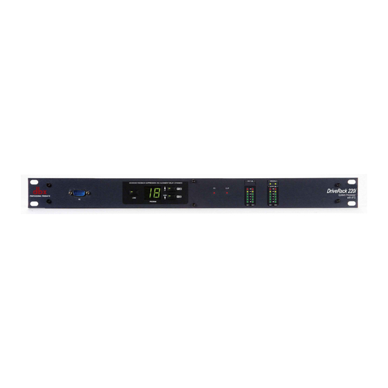
- Page 1 ® System Processor with Advanced Feedback Suppression 220i User Manual...
-
Page 2: Important Safety Instructions
IMPORTANT SAFETY INSTRUCTIONS WARNING FOR YOUR PROTECTION READ THE FOLLOWING: KEEP THESE INSTRUCTIONS HEED ALL WARNINGS The symbols shown above are internationally accepted symbols that warn of FOLLOW ALL INSTRUCTIONS potential hazards with electrical products. The lightning flash with arrowpoint in the apparatus shall not be exposed to dripping or splashing liquid and no object filled an equilateral triangle means that there are dangerous voltages present within with liquid, such as vases, shall be placed on the apparatus. -
Page 3: Electromagnetic Compatibility
8760 S. Sandy Parkway Sandy, Utah 84070, USA Date: May 31, 2012 European Contact: Your local dbx Sales and Service Office or Harman Signal Processing 8760 South Sandy Parkway Sandy, Utah... -
Page 4: Table Of Contents
220i Table Of Contents Introduction Utilities 0.1 - Defining the 220i System ............2 4.1 - Program List/Program Change ..........34 0.2 - Service Contact Info ..............3 4.2 - ZC Setup ...................34 0.3 - Warranty ..................4 4.3 - Front Panel Lockout ...............36 Getting Started Application Guide 1.1 - Rear Panel ...................6... - Page 5 220i Introduction Intro CuStomer ServICe InFo Defining the Driverack WArrAntY InFo...
-
Page 6: Defining The 220I System
0.1 - Defining the 220i System The dbx 220i is the most effective way to manage all aspects of post mixer processing and signal routing. The 220i essentially becomes the only device that you will need between the mixer and the power amps. -
Page 7: Service Contact Info
0.2 - Service Contact Info If you require technical support, contact dbx Customer Service. Be prepared to accurately describe the problem. Know the serial number of your unit - this is printed on a sticker attached to the top panel. If you have not already taken the time to fill out your warranty registration card and send it in, please do so now. -
Page 8: Warranty
In no event shall dbx or its dealers be liable for special or consequential damages or from any delay in the performance of this warranty due to causes beyond their control. -
Page 9: Getting Started
220i Section 1 Getting Started GettInG StArteD... -
Page 10: Rear Panel
220i Section 1 Getting Started 1.1 - Rear Panel IEC Power Cord Receptacle The DriveRack 220i comes with a power supply that will accept voltages ranging from 100V-120V at frequencies from 50Hz-60Hz. An IEC cord is included. EU version accepts 220V-240V at frequencies from 50Hz-60Hz. -
Page 11: Front Panel
220i Section 1 Getting Started 1.2 - Front Panel PC Connection This DB-9 type connection is used to send and receive information to and from the computer running the DriveWare™ software. NOTE: Front and rear PC connections should not be used at the same time as these connections are wired in parallel. -
Page 12: Connections
• 16 bit color • 64 meg RAM Installation • Install DriveWare from the included CD ROM or download DriveWare from the dbx website at www.dbxpro.com. • After clicking on the “.exe” install file, follow the instructions in the installer. The application will proceed to prompt you for the installation location. -
Page 13: Software Operation
220i Section 2 Software Operation SoFtWAre oPerAtIon... -
Page 14: Driverack 220I Philosophy
220i Section 2 Software Operation For your convenience, all editing functions of the DriveRack 220i are performed via the included Driveware GUI. This section has been created to act as a tutorial for performing various editing aspects of the unit. 2.1 - DriveRack 220i Philosophy The philosophy of the DriveRack 220i is built around the idea of a program. -
Page 15: Configuration
220i Section 2 Software Operation 2.4 - Configuration Configuration of the DriveRack units is done in Unit view. The DriveRack 220i configuration can be changed by clicking on the CONFIG button. Once the CONFIG button has been clicked, the modules can be changed by right clicking on the module to be changed. For example, if you want to change the processing module in one of the inserts, you simply right-click on that module and you will be able to select another processing block as well as unlink that module (if it is stereo linked). -
Page 16: Copy And Paste
220i Section 2 Software Operation 2.6 - Copy and Paste Parameters can be copied and pasted between channels in the DriveRack devices. From the program screen right click on the module that you want to copy and select Copy. To paste, right click on a like module and select Paste. -
Page 17: Storing
220i Section 2 Software Operation 2.9 - Storing Programs can be stored in the DriveRack unit or saved on the computer. To store a program in the DriveRack unit the GUI software must be on-line with the unit. The DriveRack 220i allows both program naming and along with that name you can also select where in the user program table you would like to store the program. -
Page 18: Utilities
220i Section 2 Software Operation 2.11 - Utilities The DriveRack 220i utilities can be entered by clicking on Edit on the Menu Bar and selecting Utilities. 2.12 - Online/Offline The DriveWare GUI provides a mechanism for creating programs while not physically connected to the DriveRack unit. -
Page 19: Detailed Parameters
220i Section 3 Detailed Parameters DetAILeD PArAmeterS... -
Page 20: Input Routing
220i Section 3 Detailed Parameters The 220i DriveRack offers complete editing flexibility, by offering in-depth control over every parameter within each effect module. The following section will provide you with a module block representation for each effect, as well as descriptions and explanations of all parameters within the 220i. 3.1 - Input Routing The signal routing begins at the INPUT ROUTING block of the 220i. - Page 21 220i Section 3 Detailed Parameters EQ On/Off Turns the EQ on and off. Flatten/Restore This parameter either flattens the GEQ or restores the GEQ to the last setting before flattening. The DriveRack unit allows you to leave the EQ edit window and return without losing the edited EQ settings.
-
Page 22: Advanced Feedback Suppression
220i Section 3 Detailed Parameters Q (2-8) 0.105 to 16.0 Q is adjustable from 0.105 to 16.000 Level (2-8) -12 to 12 dB Sets the overall level of the selected parametric EQ frequency. Band 9 Frequency 20 to 20k (High Shelf) Selects the frequency of the high shelf parametric EQ. - Page 23 220i Section 3 Detailed Parameters Clear Live/All This parameter clears the filters. If Clear Live is selected, then (if invoked) the live filters are reset. If Clear All is selected, then (if invoked) all of the filters are reset. When either Clear Live or Clear All is selected, the third parameter row displays “Start w/ Data Wheel.”...
-
Page 24: Automatic Gain Control (Agc)
220i Section 3 Detailed Parameters Sensitivity -20-+20dB The AFS algorithm is very effective when the audio has a nominal level of 0 dBu, however if the audio is too low in level the AFS algorithm may not catch feedback as quickly as possible. By increasing or decreasing the sensitivity you can adjust for audio that is either too loud or too soft and help the AFS function properly. -
Page 25: De-Esser
220i Section 3 Detailed Parameters Low Threshold: -60 to -30dB The Low Threshold sets a lower limit to the AGC. This prevents the AGC from adding gain to low level signals or noise. Attack: 0.20 to 5 Seconds This adjusts how fast the AGC will increase gain. Release: 30.0 to 1 dB/Second This adjusts how fast the AGC will reduce gain. -
Page 26: Ducker
220i Section 3 Detailed Parameters 3.6 - Ducker The Ducker provides a method for attenuating the signal in one channel when a signal is present in the other channel. Ducker On/Off Turns the Ducker on or off. Threshold -40 to +20dBu Threshold is the level from signal path A at which the Ducker will begin attenuating the signal passing through the Ducker (signal path B). - Page 27 220i Section 3 Detailed Parameters Compressor On/Off Turns the Compressor module on and off. OverEasy (O) Off to 10 ® There are ten levels of OverEasy that can be used for the limiters. The point when the compressor starts to compress is the “knee.” When the compressor starts to reduce the level of a signal abruptly ®...
-
Page 28: Noise Gate
220i Section 3 Detailed Parameters Gain (G) -20 to +20 dB This parameter is used to compensate for the gain lost during compression. By using heavy compression on a signal and then boosting the signal with the output gain, the user can create a signal that sounds much louder than it actually is. -
Page 29: Notch Filters
220i Section 3 Detailed Parameters Gate On/Off Turns the Gate on and off. Threshold -50 to 20 dBu The threshold is the volume level at which the gate opens. Anything above the threshold passes, while signal that is lower than the threshold is attenuated. Beware, setting the threshold to high can cut off the tail end of signals as they fade out (the sustain of a guitar note, a held piano chord, a reverb tail, etc.). -
Page 30: Matrix Mixer
220i Section 3 Detailed Parameters Gain -36 to 6 dB Sets the level of the selected notch filter. Set to +6dB to help find unwanted feedback, then set to -3dB to -36dB to remove. Q 16 to 128 Selects the Q of the selected notch filter. 3.10 - Matrix Mixer This adjusts the mix and output levels of the 220i. - Page 31 220i Section 3 Detailed Parameters PEQ On/Off Turns the PEQ band on and off. The following figure shows the constant Q parametric filter. Flatten/Restore This parameter either flattens the PEQ or restores the PEQ to its original shape. Type This parameter selects the PEQ type. Types include: 1. Bell-All parametrics are bell-shaped 2. HShelf - One shelf is High, while all others are bell 3.
-
Page 32: Bandpass Filter
220i Section 3 Detailed Parameters 3.12 - Bandpass Filter This Bandpass FIlter module allows the user to adjust the output bandwidth. Highpass Out to 20kHz Adjusts the lowest frequency that the output will achieve. Lowpass Out to 20Hz Adjusts the highest frequency that the output will achieve. 3.13 - Limiter The 220i offers a dedicated Limiter module. - Page 33 220i Section 3 Detailed Parameters OverEasy (O) Off to 10 There are ten levels of OverEasy ® that can be used for the limiters. The point when the compressor starts to compress is the “knee.” When the compressor starts to reduce the level of a signal abruptly ®...
-
Page 34: Delay
220i Section 3 Detailed Parameters Overshoot 1-6 This parameter sets the amount of overshoot for the Instantaneous Transient Clamp™. 3.14 - Delay The parameters for the delay are as follows and are user adjustable: Delay On/Off Turns the delay on and off. Length Sets the amount of delay time. -
Page 35: Subharmonic Synthesizer
220i Section 3 Detailed Parameters Polarity Positive or Negative This section is used to select either the Positive or Negative polarity. Phase 0 to 180 This parameter sets the amount of phase within the selected output path. The phase is referenced to the uppermost frequency within the band. -
Page 37: Utilities
220i Section 4 Utilities Program List Zone Control Front Panel Lockout... -
Page 38: Program List/Program Change
220i Section 4 Utilities The Utility section of the DriveRack 220i gives you the ability to perform several key operational functions including: custom Program List creation, Zone Controller set- tings, and front panel lockout mode selection. Use this section of the manual to make yourself familiar with all aspects of the Utility menu of the DriveRack system. - Page 39 220i Section 4 Utilities Programming To be programmed, each Zone Controller must have its identification set using the DIP switches on the rear of the panel. The Zone Controllers are programmed from the Utility menu in the GUI. The Zone Controllers are programmed from the Utility menu in the GUI.
-
Page 40: Front Panel Lockout
220i Section 4 Utilities 4.3 - Front Panel Lockout The Utility menu of the 220i also offers the option of performing a front panel lockout. This is the perfect security deterrent for unwanted editing. Open the utility menu by selecting Edit on the Menu Bar and then clicking on Utilities. -
Page 41: Application Guide
220i Section 5 Application Guide APPLICAtIon GuIDe... -
Page 42: Mic Processing/Mixing
220i Section 5 Application Guide ® This Application guide section is provided to offer suggested installation applications of the DriveRack units that will allow you to optimize peak performance of the units. Note that the four included ® applications represent the extensive flexibility of the DriveRack units. -
Page 43: Stereo/Dual Mono System Processing
220i Section 5 Application Guide 5.2 - Stereo/Dual Mono System Processing Hardware 1. Connect the outputs of the mixer to the inputs of the DriveRack. 2. Connect the outputs of the DriveRack to the inputs of the amplifier. 3. Making sure that all outputs are muted, apply power to the mixer and amplifiers. Software 1. -
Page 44: Room Combining
220i Section 5 Application Guide 5.3 - Room Combining Hardware 1. Connect the audio source to the inputs of the DriveRack. 2. Connect the outputs of the DriveRack to the amplifier. 3. Making sure that all outputs are muted, apply power to the mixer and amplifiers. 4. -
Page 45: Bgm/Paging
220i Section 5 Application Guide 5.4 - BGM/Paging Hardware 1. Connect the audio source to CH 2 of the DriveRack 220i. 2. Connect the outputs of the DriveRack to the amplifier. 3. Making sure that all outputs are muted, apply power to the mixer and amplifiers. 4. -
Page 47: Appendix
220i Appendix Appendix... -
Page 48: Factory Reset/Flash Update
220i Appendix A.1 - Factory Reset/Flash Update ® In the event that a reset is required, the DriveRack 220i offers you the option of performing a “Soft” or “Hard” reset. The Soft Reset resets all operating parameters except user programs. The Hard Reset Procedure will reset all programmable information back to the factory defaults. -
Page 49: Specifications
Electronically balanced, RF filtered Impedance: 120 Ω balanced, 60Ω unbalanced Max Output Level: +20dBu A/D Performance: Type: dbx Type IV™ conversion system Dynamic Range line: >113 dB A-weighted, >110 dB unweighted Type IV dynamic range: >119 dB, A-weighted, 22kHz BW >117 dB, unweighted, 22kHz BW Sample Rate:... -
Page 50: Program List
220i Appendix A.3 - Program List Factory Program List 1. Stereo & AFS - Designed for Stereo systems. 2. Two Mics - Processing for two separate microphones. 3. Mic Mix - Processing and mixing two microphones together. 4. Page 2 Zones - With a microphone in ch. 1 and music in ch. 2 this will send both music and page announcements to both outputs. -
Page 51: Block Diagram
220i Appendix A.4 - Block Diagram DriveRack User Manual ®... -
Page 52: Gain And Relay Jumpers
220i Appendix A.5 - Gain and Relay Jumpers CAUTION: These servicing instructions are for use by qualified service personnel only. To reduce the risk of electric shock, do not perform any servicing other than that contained in the operating instructions unless you are qualified to do so. -
Page 53: Tips, Tricks And Troubleshooting
220i Appendix A.6 - Tips, Tricks and Troubleshooting Speaker Tunings Various “Speaker Tunings” are available for some of the different DriveRack units; on the DriveRack 480 units speaker tunings can be downloaded from the website, whereas on the DriveRack 260 the speaker tunings are found in the Wizard function. -
Page 54: Zone Controller Wiring And Install
220i Appendix A.7 - Zone Controller Wiring and Install Zone Controller Wiring The DriveRack Zone Controllers, (ZC-1, ZC-2, ZC-3, ZC-4) can be wired serially or in parallel. To wire in series each Zone Controller must have an identification or zone number chosen using the DIP switches on the side of the controller (see diagram A). - Page 55 220i Appendix Diagram A Diagram B ID# 1 ID# 4 80-1342- A 80-1342- A Diagram C ID# 3 ID# 6 DriveRack User Manual ®...
- Page 56 220i Appendix Zone Controller Cable Speci cations: Cat 5 Cable / 4-Twisted Pairs of 24 AWG Wire / 568B Standard RJ-45 RJ-45 (8-Position) (8-Position) White / Orange Voltage Reference Orange Controller 1 1 2 3 4 5 6 White / Green Controller 2 1 2 3 4 5 6 Blue...
- Page 57 8760 South Sandy Parkway • Sandy, Utah 84070 Phone: (801) 568-7660 • Fax (801) 568-7662 Int’l Fax: (801) 568-7583 Questions or comments? E-mail us at: customer@dbxpro.com or visit our website at: www.dbxpro.com or www.driverack.com 18-0239-B...
Need help?
Do you have a question about the DriveRack 220i and is the answer not in the manual?
Questions and answers