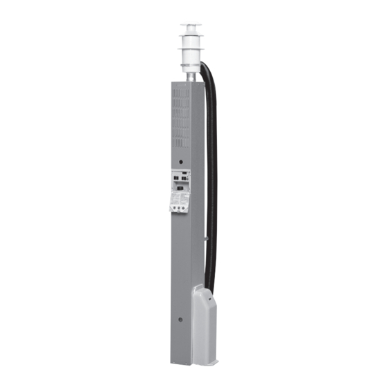
Alde Comfort 2928 Instructions For Use Manual
Hide thumbs
Also See for Comfort 2928:
- Instructions for use manual (32 pages) ,
- Installation instructions manual (16 pages) ,
- Service manual (28 pages)
Summary of Contents for Alde Comfort 2928
- Page 1 Installationsanvisning - Comfort 2928 Instructions for use - Comfort 2928 Betriebsanweisung - Comfort 2928...
- Page 2 Ø14 max 500 120-125...
- Page 3 42 1 min 150...
- Page 4 Kapitel Sida en garderob, bör en skiljevägg sättas dit, så att bränn- bart material ej kan komma i kontakt med varma delar. Teknisk data Är varmvattenberedare och elpatron monterade på Montering av värmepannan värmepannan, gör då hål i skiljeväggen enligt fig 3 för Montering av värmepanna att kunna komma åt varmvattenberedarens luftskruv inbyggd i skåp...
- Page 5 en genom ventilation strumman och golvet. Skruva fast DAnMArK ventilations trumman i golv och värmepanna. Danmarks Gasmateriel Prøvning “Gasreglementets Om värmepannan monteras i t.ex. en garderob, bör afsnitt B-3 for F-gas anlæg i campingvogne” m.m. skall en skiljevägg sättas dit, så att brännbart material ej tillæmpas.
- Page 6 inkopplat från fabrik. Kablar får ej läggas intill eller på Fig 12 elementbehållaren. Utgående vatten VArnInG: 230 volt skall vara väl skiljt från 12 volt. Returvatten Fig 10 Ventilationstrumma Kopplingsplint Konvektor Säkring 1 amp Luftnippel Rumstermostat Avtappningskran Batteri 12 volt Rumstermostat Värmepanna sedd uppifrån Anslutning till värmesystemet...
- Page 7 • Kontrollera att reduceringsventilen är på rätt tryck. För att ytterligare öka säkerheten rekommenderas montering av Alde gasolläckagetestare. Denna mon- teras närmast reduceringsventilen och med ett tryck på en knapp kontrollerar man lätt om installationen är tät.
-
Page 8: Fitting The Boiler
FITTInG THE BoILEr Chapter page Technical data Mark out where the boiler is to stand. If the boiler is Fitting the boiler to be positioned against a wall or bulkhead made of a Mounting a boiler in a cupboard inflammable material, a 1 mm air gap must be allowed. Fitting the flue terminal Make holes in the floor, one for the ventilation duct and LPG Installation... - Page 9 tube and one for the ventilation drum, if one is to be Fig 4 mounted (see Figure 1 in the installation instructions). The boiler from above The ventilation drum can be placed either to the left or Centre marking for the chimney to the right, depending on the space available.
- Page 10 The pipes should with the aid of Alde’s filling pump. This pump both fills be run horizontally and air screws should be located at and bleeds the system. If the system is filled manually, suitable places where air cannot escape by itself, e.g.
- Page 11 • Check that the reduction valve is at the right pressure. We recommend the mounting of an Alde LP gas leak- age tester in order to further increase safety. The tester is mounted closest to the reducing valve and enables you to test that the system does not leak by simply pushing a button.
-
Page 12: Table Of Contents
Kapitel Seite soll. Den hinter dem unteren Verkleidungsblech befind- lichen Plastikschlauch ausrollen, dessen Ende spitz Technische Daten zu schneiden und durch Frischluftkasten sowie Boden Installation des Kessels ver legen. Frischluftkasten an Boden und Kessel fest- Montage eines Kessels, der in einem schrauben. -
Page 13: 2:2 Installations Des Schornsteins
des Warm wasserbereiters, der Abzapfhahn sowie der Abb. 5 Rück stellknopf für den Überhitzungsschutz auf der Schornsteinhaube Elektro patrone zugänglich sind. Ansaug stutzen Abb. 1 Schornsteinrohr Loch für Frischluftkasten Flüssiggasinstallation Entwässerungsschlauch Die Flüssiggasinstallation des Heizkessels soll gemäß Abb. 2 der Vorschriften der VFG und DVGW-Bestimmungen Loch zur Befestigung des Kessels ausgeführt werden. -
Page 14: Installation Der Heizanlage
Die Rohrverlegung erfolgt waagerecht unter Anbringung von Entlüftungschrauben an geeigneten Die Füllung des Systems erfolgt im Expansions- behälter, entweder manuell oder mit Hilfe der Alde- Stellen, an denen die Luft nicht entweichen kann, Auffüllpumpe, die sowohl das System auffüllt als auch z.B. -
Page 15: Anschluß Des Heißwasserbereiters
Überprüfen, dass das Reduzierventil den richtigen Druck aufweist. • Um die Sicherheit zusätzlich zu erhöhen, wird die Montage eines Alde-Flüssiggasleckagetesters emp fohlen. Dieser wird in der Nähe des Reduzierventils montiert. Mit einem Knopfdruck wird einfach kontrol liert, ob die Installation dicht ist. - Page 16 Alde International Systems AB Wrangels allé 90 • Box 11066 • 291 11 Färlöv • Kristianstad • Sweden Tel +46 (0)44 712 70 • Fax +46 (0)44 718 48 • www.alde.se • e-mail: info@alde.se...


Need help?
Do you have a question about the Comfort 2928 and is the answer not in the manual?
Questions and answers