
Related Manuals for Honeywell NetAXS NX4S1


Summary of Contents for Honeywell NetAXS NX4S1
-
Page 1: Installation Guide
NetAXS™ NX4S1 Access Control Unit Installation Guide May 2007 © 2007 Honeywell. All rights reserved. 800-00008, Revision A... - Page 2 Ordering Information Please contact your local Honeywell representative or visit us on the web at www.honeywellaccess.com for information about ordering. Feedback Honeywell appreciates your comments about this manual. Please visit us on the web at www.honeywellaccess.com to post your comments.
-
Page 3: Table Of Contents
4.5 Communications ......................16 RS-232 Communications ..................... 16 RS-485 Communications ..................... 18 Ethernet TCP/IP Communications ................19 4.6 DIP Switch Settings ...................... 21 4.7 Jumper Settings......................23 4.8 Downstream I/O......................23 NetAXS Access Control Unit NX4S1 Installation Guide, Document 800-00008, Revision A... - Page 4 6.1 LED Operation......................42 7.0 Hardware Specifications ......................... 7.1 Relay Contacts ......................44 7.2 Reader Interface ......................44 7.3 NX4S1 Wire Requirements ..................44 7.4 Maximum Output Loading ................... 44 7.5 Common Connections....................45 7.6 Mechanical........................45 7.7 Environment........................45 7.8 Communications and Wiring ..................
- Page 5 A.4.3 Reader Tamper Inputs....................60 A.4.4 Door Egress Inputs....................60 A.4.5 Door Status Inputs..................... 61 A.4.6 ACFAIL and Panel Tamper Inputs ................61 A.4.7 Additional Generic Outputs ..................62 NetAXS Access Control Unit NX4S1 Installation Guide, Document 800-00008, Revision A...
- Page 6 www.honeywell.com...
- Page 7 Figure 30: N-485-PCI-2/NetAXS™ Access Controller Panel Connection Detail ..40 Figure 31: NetAXS™/NetAXS™ Access Controller Panel Connection Detail ..41 Figure 32: System, Relay and Power LEDs ............... 42 Figure 33: NX4S1 Panel Wiring Diagram ..............47 NetAXS Access Control Unit NX4S1 Installation Guide, Document 800-00008, Revision A...
- Page 8 www.honeywell.com...
-
Page 9: Ist Of
Table 4 MIRO 32/0 DIP Switch and Jumper Settings ............. 23 Table 5 LED Status ........................43 Table 6 Communications and Wiring ..................46 Table 7 Reader Wiring ......................46 Table 8 Troubleshooting Problems and Solutions ..............48 NetAXS Access Control Unit NX4S1 Installation Guide, Document 800-00008, Revision A... - Page 10 www.honeywell.com...
-
Page 11: Netaxs™ Nx4S1 Installation
If any damage to the shipment is noticed, a claim must be filed with the Caution: commercial carrier responsible. Electro-static discharge (ESD) can damage CMOS integrated circuits and Caution: modules. To prevent damage always follow these procedures: NetAXS Access Control Unit NX4S1 Installation Guide, Document 800-00008, Revision A... -
Page 12: Product Liability, Mutual Indemnification
Customer harmless for any costs or damages including reasonable attorneys’ fees which the Customer may be required to pay as a result of the defective Product or the negligence of Honeywell, its agents or its employees. -
Page 13: Federal Communications Commission
This Class B digital apparatus meets all requirements of the Canadian Interference-Causing Equipment Regulations. Cet appareil numérique de la classe B respecte toutes les exigences du Réglement sur le matériel brouilleur du Canada. NetAXS Access Control Unit NX4S1 Installation Guide, Document 800-00008, Revision A... -
Page 14: Underwriters Laboratories Incorporated
The NetAXS™ panel is not intended as a Proprietary Alarm Unit - Category APOU, UL1076 standard. The NetAXS™ panel was reviewed using the following Honeywell readers: OmniAssure (TM) OT30, OmniClass (TM) OM40 and OM55, and OmniProx (TM) OP30 and OP40. -
Page 15: Introduction
RS-232, RS-485, or Ethernet network protocols. This document describes how to install and configure the NX4L1 access control unit. NetAXS Access Control Unit NX4S1 Installation Guide, Document 800-00008, Revision A... -
Page 16: Panel Components And Descriptions
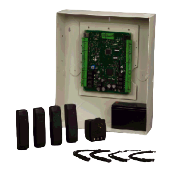
Panel Components and Descriptions 3.0 Panel Components and Descriptions The NX4S1 access control unit consists of a NetAXS™ panel control board and battery. The components are enclosed in a pre-wired cabinet. The 16.5 VAC power supply (Basler Electric Model BE156250CAA0004, M&G Electronics Model MGT1650, or Honeywell Access Systems part number X-4) provides power for the panel control board, which is a four-reader panel providing access control for up to four doors. -
Page 17: Netaxs™ Access Control Unit
600 mA: Reader 1 + Reader 2 + Reader 3 + Reader 4 + AUX Power < 600 mA. AUX Power must not be used to power locks. Caution: For NetAXS™ maximum current draw, refer to Hardware Specifications, page 44. NetAXS Access Control Unit NX4S1 Installation Guide, Document 800-00008, Revision A... -
Page 18: Power Supply
The NetAXS™ panel is capable of operating on AC or DC input power. UL has not reviewed the use of a DC power supply with the NX4S1 panel. The AC input must be supplied at 16.5 VAC utilizing one of the following UL-listed, 50 VA, Class 2 transformers: Basler Electric Model BE156250CAA0004, M&G Electronics Model... -
Page 19: Installation
12.If you are using a battery backup function, place the 7 A-Hr battery in the enclosure. 13.Attach the positive (red) Power Supply-to-Battery cable to the positive (red) battery terminal. NetAXS Access Control Unit NX4S1 Installation Guide, Document 800-00008, Revision A... -
Page 20: Cabinet Mounting
All dimensions are given in inches. See Table 1 on page 14 for dimensions of the conduit entries into the cabinet. Figure 2: NetAXS™ NX4S1 Panel Cabinet, Front View 31/32" (25 mm) 1/4" (6.25 mm) 2 30/32"" (75 mm) 2 30/32"... -
Page 21: Figure 3: Netaxs™ Nx4S1 Panel Cabinet, Top View
All knockouts punched through for easy removal without damage to cabinet 1 3/32" (28.125 mm) diameter knockout 14/16" ( 21.875 mm) diameter knockout 3/4" (18.75 mm) 1 16/32" (38.275 mm) Back NetAXS Access Control Unit NX4S1 Installation Guide, Document 800-00008, Revision A... -
Page 22: Figure 5: Netaxs™ Panel Cabinet, Left View
NetAXS™ NX4S1 Installation Installation Figure 5: NetAXS™ Panel Cabinet, Left View Back 7/8" (21.875 mm) diameter knockout 1 15/32" (37.5 mm) 3/4" (18.75 mm) www.honeywell.com... -
Page 23: Figure 6: Netaxs™ Nx4S1Panel Cabinet, Right View
NetAXS™ NX4S1 Installation Installation Figure 6: NetAXS™ NX4S1Panel Cabinet, Right View Back 7/8" (21.875 mm) diameter knockout NetAXS Access Control Unit NX4S1 Installation Guide, Document 800-00008, Revision A... -
Page 24: Reader Wiring
NetAXS™ NX4S1 Installation Installation 4.2 Reader Wiring Each reader port supports a single 12-volt reader with Wiegand output format. Power to the readers is shared with the AUX Power ports TB3 and TB14. The maximum power draw is 600 mA for readers and AUX Power combined. -
Page 25: Figure 7: Typical Supervised Input Wiring Diagram
The wire used for the inputs should be shielded and cannot exceed 30 ohms over the entire length of the cable. Remember that the distance from the panel to the door must be doubled to determine the total resistance. NetAXS Access Control Unit NX4S1 Installation Guide, Document 800-00008, Revision A... -
Page 26: Nx4S1 Control Output Wiring
Caution: Alarm units and systems. 4.4 NX4S1 Control Output Wiring Relay 1 is defaulted for control of the Door 1 lock, Relay 2 is defaulted for the control of the Door 2 lock, Relay 3 is defaulted for the control of the Door 3 lock, and Relay 4 is defaulted for the control of the Door 4 lock. -
Page 27: Figure 8: Rj-45 Serial Port
Installation Figure 8 on page 17 illustrates the connections for an RS-232, DB9 (9 pin) connector to the panel’s RJ-45 serial port. Replacement cables can be obtained by contacting your Honeywell Access System Representative. Figure 8: RJ-45 Serial Port Figure 9: RS-232 Configuration... -
Page 28: Rs-485 Communications
NetAXS™ NX4S1 Installation Installation RS-485 Communications The NetAXS™ panel can reside on an existing RS-485 drop line hosted by either a NetAXS™ panel configured as a Gateway, or N-485-PCI-2, PCI-3, or N-485-HUB-2 (see Figure 10 on page 18, Figure 11... -
Page 29: Ethernet Tcp/Ip Communications
Each NetAXS™ panel has a port for an Ethernet TCP/IP interface (see Figure 12, Ethernet TCP/IP Configuration). The Ethernet TCP/IP interface provides 10/100 Mbit Ethernet support for each panel. Up to 31 panels can be configured on each TCP/IP connection. NetAXS Access Control Unit NX4S1 Installation Guide, Document 800-00008, Revision A... -
Page 30: Figure 13: Ethernet Mac Address Location
NetAXS™ NX4S1 Installation Installation Figure 13 on page 20 shows the location of the panel’s unique MAC ID. Figure 13: Ethernet MAC Address Location Label with Ethernet MAC Address www.honeywell.com... -
Page 31: Dip Switch Settings
NetAXS™ NX4S1 Installation Installation 4.6 DIP Switch Settings Figure 14 on page 21 locates the NX4S1 DIP switch panel and the J36 and J37 (termination and biasing) jumpers. Figure 14: DIP Switch and Jumper Locations Switches NetAXS Access Control Unit NX4S1 Installation Guide, Document 800-00008, Revision A... -
Page 32: Table 3 Dip Switch Settings
NetAXS™ NX4S1 Installation Installation Use the following DIP switch configurations to set the panel address. Table 3 DIP Switch Settings Selection Address 1 (default) Address 2 Address 3 Address 4 Address 5 Address 6 Address 7 Address 8 Address 9... -
Page 33: Jumper Settings
Installation 4.7 Jumper Settings The NX4S1 panel control board includes jumpers 36 and 37, which set end-of-line termination and biasing for the Multidrop RS-485 line. The board ships with all jumpers set to OFF. For a Multidrop RS-485 line, you must set both J36 and J37 to CLOSED (terminated and biased) at the two end-point panels. - Page 34 NetAXS™ NX4S1 Installation Installation Table 4 MIRO 32/0 DIP Switch and Jumper Settings (continued) Module Setting Value Jumper settings JP1 - CLOSED (if the module is the last module on the downstream bus), OPEN (if the module is not the last module on...
-
Page 35: Netaxs Access Control Unit Nx4S1 Installation Guide, Document 800-00008, Revision A Iii
The following figure shows the default downstream I/O system configuration with communication and power wiring. This configuration has not been reviewed by UL. Figure 15: Default Downstream I/O Configuration with Wiring NetAXS Access Control Unit NX4S1 Installation Guide, Document 800-00008, Revision A... -
Page 36: System Configuration
NetAXS™ NX4S1 Installation System Configuration 5.0 System Configuration This section provides wiring diagrams for each of the NetAXS™ system configurations. 5.1 RS-485 Connection via PCI-2 This connection supports thirty-one NetAXS™ Access Controller panels for each drop line. It has been reviewed by Underwriters Laboratories Incorporated (UL). Note that PCI-2 units can also be wired anywhere along the drop line. -
Page 37: Rs-485 Connection Via Netaxs
120 ohm, 23 pf (HAS part no. NCP2441- See RS-485 Cable Note Only Earth Ground (EG) one side of cable It is recommended to Earth Ground (EG) each NetAXS enclosure individually NetAXS Access Control Unit NX4S1 Installation Guide, Document 800-00008, Revision A... -
Page 38: Rs-485 Connections With Multidrop Panels At Both Ends Of The Cable
NetAXS™ NX4S1 Installation System Configuration 5.3 RS-485 Connections with Multidrop Panels at Both Ends of the Cable You can connect Multidrop panels at both ends of an RS-485 cable via either a NetAXS™ panel or a PCI-2 device. These configurations have not been reviewed by UL. -
Page 39: Figure 19: Rs-485 Connection Via Pci-2 With Multidrop Panels At Both Ends
J36 OPEN J37 OPEN NetAXS Panel n y ar roun one side of cable one side of cable It is recommended to Earth Ground (EG) each NetAXS enclosure individually NetAXS Access Control Unit NX4S1 Installation Guide, Document 800-00008, Revision A... -
Page 40: Rs-232 Connection
NetAXS™ NX4S1 Installation System Configuration 5.4 RS-232 Connection This connection supports one NetAXS™ Access Controller panel for each COM port. It has been reviewed by UL. However, because UL has reviewed the NetAXS™ panel only as a standalone system, the computer terminal and NetAXS™ gateway panel appear in this section only to illustrate the installation and programming of the NetAXS™... -
Page 41: Ethernet Connection
This connection supports a maximum of 255 IP connections per server. It has not been reviewed by Figure 21: Ethernet Connection 100BaseT (CAT 5) 328 Ft. Max. Terminal RS-485 Multidrop DIP Switch Settings S1-S5 Panel Address S6: OFF NetAXS Panel NetAXS Access Control Unit NX4S1 Installation Guide, Document 800-00008, Revision A... -
Page 42: Lansrlu1 Connection
NetAXS™ NX4S1 Installation System Configuration 5.6 LANSRLU1 Connection This connection supports thirty-one panels for each drop line and a maximum of 255 IP connections. It has not been reviewed by UL. Note that PCI-2 units can also be wired anywhere along the drop line. -
Page 43: Rs-485 Short Haul Modem Connection Via Pci-2
2 (TX) 2 (RX) 3 RX 3 (RX) or 3 (TX) 5 Comm 7 (GND) 7 (GND) Refer to 485-PCI/NetAXS Panel S8: OFF )19,200 Baud Rate) Connection Detail diagram NetAXS Access Control Unit NX4S1 Installation Guide, Document 800-00008, Revision A... -
Page 44: Rs-485 Short Haul Modem Connection Via Netaxs
NetAXS™ NX4S1 Installation System Configuration 5.8 RS-485 Short Haul Modem Connection via NetAXS™ Thirty-one NetAXS™ Access Controller panels for each drop line. It has not been reviewed by UL. Figure 24: RS-485 Short Haul Modem Connection via NetAXS™ RS232 Cable... -
Page 45: Rs-232 Short Haul Modem Connection
(RS-232 50 Ft. Max.) (DB-9) (Straight) (Null) Male 9 Pin Male 25 Pin 2 TX 2 (TX) 2 (RX) 3 RX 3 (RX) or 3 (TX) 5 Comm 7 (GND) 7 (GND) NetAXS Access Control Unit NX4S1 Installation Guide, Document 800-00008, Revision A... -
Page 46: M-56K Dial-Up Modem, Rs-485 Connection Via Hub
NetAXS™ NX4S1 Installation System Configuration 5.10 M-56K Dial-up Modem, RS-485 Connection via Hub Thirty-one NetAXS™ Access Controller panels for each drop line. It has not been reviewed by UL. Figure 26: M-56K Dial-up Modem, RS-485 Connection via Hub M-56K FAX/MODEM... -
Page 47: M-56K Dial-Up Modem, Rs-485 Connection Via Netaxs
NetAXS Panels TB7-1 (RS485+) TB7-2 (RS485-) TB7-3 (RS485 COM) 4,000 ft. (1,200 m) max, 24 AWG, 2 twisted pairs with shield, 120 ohm, 23 pf (HAS part no. NCP2441-TN) NetAXS Access Control Unit NX4S1 Installation Guide, Document 800-00008, Revision A... -
Page 48: Fiber Converter To Rs-485 Connection Via Pci-2
NetAXS™ NX4S1 Installation System Configuration 5.12 Fiber Converter to RS-485 Connection via PCI-2 This connection supports thirty-one NetAXS™ Access Controller panels for each drop line. It has not been reviewed by UL. Note that PCI-2 units can also be wired anywhere along the drop line. See... -
Page 49: Fiber Converter To Rs-485 Connection Via Netaxs
S1-S5 Panel Address S6: OFF 4,000 ft. (1,200 m) max, 24 AWG, 2 twisted pairs with J36: OPEN shield, 120 ohm, 23 pf (HAS part no. NCP2441-TN) J37: OPEN NetAXS Access Control Unit NX4S1 Installation Guide, Document 800-00008, Revision A... -
Page 50: N-485-Pci-2/Netaxs™ Access Controller Panel Connection Detail
NetAXS™ NX4S1 Installation System Configuration 5.14 N-485-PCI-2/NetAXS™ Access Controller Panel Connection Detail This diagram has not been reviewed by UL. Note that PCI-2 units can also be wired anywhere along the drop line. See Figure 18 on page 28 and Figure 19 on page 29. -
Page 51: Netaxs™/Netaxs™ Access Controller Panel Connection Detail
SHIELD side of cable shield NetAXS Panel Shield Common 485 + 485 - NetAXS TB7 4,000 ft.(1,200 m) max,24 AWG,2 twisted pairs with shield,120 ohm,23 pf (NCI part no.NCP2441-TN) NetAXS Access Control Unit NX4S1 Installation Guide, Document 800-00008, Revision A... -
Page 52: Netaxs™ Startup
NetAXS™ NX4S1 Installation NetAXS™ Startup 6.0 NetAXS™ Startup 6.1 LED Operation When the panel wiring is complete, turn on the power. It might take a few minutes for the panel to complete the power-up sequence. When the board does initialize, verify that the appropriate LEDs... -
Page 53: Table 5 Led Status
TX & TX & Data Data Data Data Power Mal- 10Mbit Relay Normal function Link The Ethernet/COM status LED will be green even if no cable is attached. Note: NetAXS Access Control Unit NX4S1 Installation Guide, Document 800-00008, Revision A... -
Page 54: Hardware Specifications
• Reader Data Input: TTL compatible inputs. • Reader Buzzer Output: Open collector driver capable of sinking 8 mA at 15 VDC. 7.3 NX4S1 Wire Requirements • Power: One twisted pair shielded, 18 AWG. • RS-485: 24 AWG, 4,000 ft. (1,200 m) max, twisted pairs with shield, 120 ohm, 23 pf (HAS part number NC2441-TN). -
Page 55: Common Connections
• Enclosure Weight, including 7 A-Hr battery: 22.1 pounds (10 kg) 7.7 Environment • Temperature: 0C to 49C operating, -55C to +85C storage. • Humidity: 5% to 85% RHNC. NetAXS Access Control Unit NX4S1 Installation Guide, Document 800-00008, Revision A... -
Page 56: Communications And Wiring
NetAXS™ NX4S1 Installation Hardware Specifications 7.8 Communications and Wiring Table 6 Communications and Wiring Maximum Maximum Distance: Communication Type Description Panels Feet (Meters) Direct to COM Port CBL50, RS-232 Cable 9-pin to RJ-45 50 (15) N-485-PCI-2 RS-485 9-pin to CPU... -
Page 57: Nx4S1 Wiring Diagram
HAS 3-000066 12VDC, 7AHr Maintain at least a .25-inch distance between the non-power limited wiring (battery Note: backup/charger wiring) and all other wiring, which is power-limited Class 2 wiring. NetAXS Access Control Unit NX4S1 Installation Guide, Document 800-00008, Revision A... -
Page 58: Maintenance
8.0 Maintenance Perform the following maintenance on the NetAXS™ enclosure: • Change the CASIL CA1270 lead-acid battery (Honeywell Access Systems part number 3-000066) every two to two and a half years. Do not connect an uncharged battery to the panel. -
Page 59: Technical Support
10.1 Normal Support Hours Monday through Friday, 7:00 a.m. to 7:00 p.m. Central Standard Time (CST), except company holidays: (800) 323-4576. 10.2 Web For technical assistance please visit http://www.honeywellaccess.com NetAXS Access Control Unit NX4S1 Installation Guide, Document 800-00008, Revision A... - Page 60 NetAXS™ NX4S1 Installation Technical Support www.honeywell.com...
-
Page 61: Netaxs™ Standalone Operation
NetAXS™ Standalone Operation A.1 Basic Standalone Operations A.1.1 Card Read / Door Lock Operation 1. Present a card to a reader. 2. The reader sends the card number to a reader input on the panel. 3. The panel searches its database and: •... -
Page 62: Standalone Settings
• Echo typed characters locally: YES • Line Delay: 500 milliseconds A.2.4 Verifying Communications 1. Press the spacebar. 2. Press the carriage return <CR>. “S?” apppear for every online panel and indicates proper communication between the terminal and panel. www.honeywell.com... -
Page 63: Standalone Commands
NetAXS™ Standalone Operation Standalone Commands A.3 Standalone Commands Use the following commands, in the order they are listed, to configure the NetAXS™ panel. 1. T command: Sets the panel’s Time 2. D command: Sets the panel’s Date 3. L command: Creates Time zones for use by the cards 4. -
Page 64: D (Date) Command
This command would set panel 1 to a date of 1/9/2007 and to Tuesday as the day of the week. Example #2: _D=25_12/14/2009_7<CR> This command would set panel 25 to a date of 12/14/2009 with a day of week being Monday. www.honeywell.com... -
Page 65: L (Time Zone) Command
NetAXS™ Standalone Operation Standalone Commands A.3.3 L (Time Zone) Command _L=pn_tz_h1:m1-h2:m2_days<CR> Variables: pn = panel number (1-31) tz = time zone number (1-255) h1 = start time zone: hours (00-23) (Military time) m1 = start time zone: minutes (00-59) h2 = end time zone: hours (00-23) (Military time) m2 = end time zone: minutes (00-59) days = days of week valid values as listed below: 1 = Monday... -
Page 66: C (Card Add) Command
Variables: pn = panel number (1-31) code = card number (range depends on card format) Example #1: _C=6_12345<CR> This command would remove card 12345 from panel 6. Example #2 _C=18_52989<CR> This command would remove card 52989 from panel 18. www.honeywell.com... -
Page 67: W (Input) Command
NetAXS™ Standalone Operation Standalone Commands A.3.6 W (Input) Command _W=pn_input_{SO|SC|NO|NC}<CR> Variables: SO: Supervised normally open SC: Supervised normally closed NO: Non-supervised normally open NC: Non-supervised normally closed (default) Example: _W=1_9_SO<CR> Input 9 has been programmed as supervised, normally open on panel 1. A.3.7 P (Interlock) Command _P=pn_I/O_[number]_I/O[number]_{D|E|F|N|P}_ {D|E|F|N|P}<CR>... -
Page 68: Flow Control Disable/Enable
(Use this command only for a dropline panel using RS-232 in standalone mode) _U=[panel name]_{D|E} Parameters: D: Disable E: Enable Example: _U=30_D This disables the flow control on panel 30 and prevents the panel’s buffers from filling. After a hard re-set of the panel, the flow control is re-enabled. www.honeywell.com... -
Page 69: Netaxs™ Panel Defaults
NetAXS™ Standalone Operation NetAXS™ Panel Defaults A.4 NetAXS™ Panel Defaults A.4.1 Reader Ports The panel accepts a Wiegand serial data packet from the card reader. If the card is in the database, the associated relay is activated. If the card is not in the database, the relay state is unchanged. -
Page 70: Reader Tamper Inputs
Normally Closed contact. When the egress input is active, the associated output relay will be active. The following are the default egress input associations: Egress input Controls relay... Panel input Reports as... Input 1 Input 3 Input 5 Input 7 www.honeywell.com... -
Page 71: Door Status Inputs
NetAXS™ Standalone Operation NetAXS™ Panel Defaults A.4.5 Door Status Inputs The panel has a Door Status input for each door. The default condition is a two-state input configured as a Normally Closed contact. The following are the default door status input associations: Door Status input Panel input Reports as... -
Page 72: Additional Generic Outputs
NetAXS™ Standalone Operation NetAXS™ Panel Defaults A.4.7 Additional Generic Outputs The panel has the following four additional generic form C relay outputs that can be programmed using the P command: Relay output Controls... Output 5 Output 6 Output 7 Output 8 www.honeywell.com... - Page 73 Honeywell Access Systems 135 W. Forest Hill Avenue Specifications subject to change Oak Creek, WI 53154 without notice. United States 800-323-4576 © Honeywell. All rights reserved. 414-766-1798 Fax www.honeywellaccess.com Document 800-00008, Revision A...