Panasonic Toughbook CF-19KDRAXCM Service Manual
Notebook computer
Hide thumbs
Also See for Toughbook CF-19KDRAXCM:
- Reference manual (148 pages) ,
- Operating instructions manual (40 pages)

Related Manuals for Panasonic Toughbook CF-19KDRAXCM


Summary of Contents for Panasonic Toughbook CF-19KDRAXCM
-
Page 1: Notebook Computer
ORDER NO. CPD0811210CE Notebook Computer CF-19KDRAXCM Model No. This is the Service Manual for the following areas. M …for U.S.A. and Canada © Panasonic Corporation 2008. Unauthorized copying and distribution is a violation of law. -
Page 2: How To Replace The Fuse
If you lose the fuse cover the plug must not be used until a replacement cover is obtained. A replacement fuse cover can be purchased from your local Panasonic Dealer. IF THE FITTED MOULDED PLUG IS UNSUITABLE FOR THE SOCKET OUTLET IN YOUR HOME THEN THE FUSE SHOULD BE REMOVED AND THE PLUG CUT OFF AND DISPOSED OF SAFELY. -
Page 3: Laser Safety Information
LASER SAFETY INFORMATION For U.S.A Class 1 LASER-Product This product is certified to comply with DHHS Rules 21 CFR Subchapter J. This product complies with European Standard EN60825 (or IEC Publication 825) For all areas This equipment is classified as a class 1 level LASER product and there is no hazardous LASER radiation. Caution: (1) Use of controls or adjustments or performance of procedures other than those specified herein may result in hazardous radiation exposure. -
Page 4: Safety Precautions
SAFETY PRECAUTIONS 1. Before servicing, unplug the power cord to prevent an electric shock. 2. When replacing parts, use only manufacture's recommended components for safety. 3. Check the condition of the power cord. Replace if wear or damage is evident. 4. - Page 5 Note that the Use of battery packs other than those manufactured and recharging time varies based on the usage condi- supplied by Panasonic may present a safety hazard tions. (Recharging takes longer than usual when (generation of heat, ignition or rupture).
- Page 6 10-1 11-1...
-
Page 7: Specifications
1. Specifications To check the model number: Check the bottom of the computer or the box the computer came in at the time of purchase. To check CPU speed, memory size and the hard disk drive (HDD) size: Run the Setup Utility ( Reference Manual “Setup Utility”) and select [Information] menu. - Page 8 cations °C °C °F °F Operation Environment Temperature: 5 to 35 to 95 Humidity: 30 to 80 RH (No condensation) °C °C °F °F Storage Environment Temperature: -20 to 60 to 140 Humidity: 30 to 90 RH (No condensation) Operating System ®...
- Page 9 SD Memory Cards that support high-speed transfer rates can be used. Windows ReadyBoost function is also supported. to 8 Operation on other SD equipment is not guaranteed. This computer is not compatible with MultiMediaCards. Do not insert this type of cards. Theoretical value and not the actual speed.
-
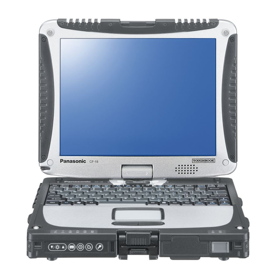
Page 10: Names And Functions Of Parts
2. Names and Functions of Parts A: Wireless LAN Antenna G: Bluetooth Antenna <Only for model with wireless LAN> <Only for model with Bluetooth> Reference Manual “Wireless LAN” Reference Manual “Bluetooth” B: Stylus/Digitizer pen Holder H: Display Release Latch C: Touch Pad page 12 “Switching to the Tablet mode”... - Page 11 Left side <Only for model with Camera> <Only for model without Camera> When recording in stereo using a stereo microphone: A: DC-IN Jack B: USB Port Click (Start) - [Control Panel] - [Hardware and Reference Manual “USB Devices” Sound] - [Sound] - [Recording] - [Microphone] - C: IEEE 1394 Interface Connector [Properties], and then add a check mark for [No Au- Reference Manual “IEEE 1394 Devices”...
- Page 12 3 Block Diagram 1.5V Interface...
- Page 13 4 Diagnosis Procedure 4.1. Basic Procedures...
- Page 14 4.2. Troubleshooting Flow Chart...
- Page 15 5 Power-On Self Test (Boot Check)
- Page 16 6 List of Error Codes <Only when the port replicator is connected> nnnn nnnn nnnn nnnn nnnn nnnn...
- Page 17 device device device device nnnn nnnn nnnn nnnn...
-
Page 18: Self Diagnosis Test
1. The power supply of the computer is turned on. 2. " F2 " is pushed on the screen of "Panasonic" while " press <F2 to enter Setup> " is displayed. 3. The setup utility starts and then takes notes of the content of the BIOS setup of present set. - Page 19 2. Operation of PC-Diagnostic Utility -Only the device which can be inspected on the entire screen is displayed. -The item does not appear when the device of wireless LAN etc. is not physically connected. -The movement of the item must use an arrow key or a flat pad. -As for the device under the diagnosis, blue and yellow are alternately displayed at the left of the icon.
- Page 20 1. Turned on the computer. 2. "F2" is pushed on the screen while "Press<F2>to enter Setup" is displayed of "Panasonic". 3. Push "F10", and on the screen of "Is the change in the setting preserved and do end?"and then "Yes"...
- Page 21 3. Test Item and Division of trouble Enhan- Place with possibili- Test item Stanard Content of standard test Content of enhancing test cing ty of breakdown CPU is shifted to protected mode, and "Violation of the paging", "Operation of CPU / CPU / the violation of a privileged instruction", Main board...
-
Page 23: Wiring Connection Diagram
8 Wiring Connection Diagram LED MODULE Touch BT PCB WLAN Screen LED PCB Panel HSDPA PCB DIGITIZER WWAN SERIAL EXTERNAL JK601 PORT DISPLAY PORT I/F PCB CN881 CN882 JK600 CN851 CN880 CN883 CN604 JK880 CN600 DC-IN I/O PCB JK962 JK963 H/P MIC CN16 JK960 JK961... -
Page 24: Disassembly Instructions
9 Disassembly/Reassembly Note: Power off the computer. Do not shut down to the Suspend or hibernation mode. Do not add peripherals while the computer is in the Suspend or hibernation mode; abnormal operation may result. 9.1. Disassembly Instructions 9.1.1. Disassembly Flowchart The chart below shows the various parts which should be removed in order to remove the parts that are to be replaced. - Page 25 9.1.2. Preparation HDD Case B Before disassembling, be sure to make the following prepara- Hooks tions. • Shut down Windows and turn off the power. Hooks • Disconnect the AC adaptor. HDD FPC • Remove the optional DIMM memory card and PCMCIA card if they are connected.
- Page 26 7. Disconnect the Cable from Connector (CN18). 8. Remove the Keyboard. 9. Remove the TP Tape. 10. Disconnect the Cable from Connector (CN800). 11. Remove the Touch Pad and Click Button Plate. Screws <N1> : DFHE5025XA Screws <N9> : DRSB2+5FKL 9.1.5.
- Page 27 9.1.7. Removing the DU Lid Unit <N19> <K14-9> Connector(CN1) Bluetooth PCB <K14-9> <K14-9> Plate Antenna Cable(blue) <K14-9> Clamper Connector(CN604) HSDPA PCB <K14-9> DIMM Lid Angle <N19> <N19> DU Lid 6. Disconnect the Antenna Cable from the Clamper. 1. Remove the 7 Screws <K14-9>. 7.
- Page 28 9.1.10. Removing the Main PCB, Wireless <N8> Module, SD PCB, Antenna PCB and <N8> Modem PCB Connector Guide <N19> <N19> Connector (CN882) <N9> <N9> SD PCB Ass’y Connector(CN8) BAT FPC Ass’y Connector(CN17) Note: This procedure is not necessary if the computer is not equipped with Wireless Module or Modem PCB.
- Page 29 9.1.11. Removing the I/O PCB Ass'y 12. Remove the 2 Screws <N19>, and remove the Wireless Module. 13. Remove the 2 Screws <N19>, and remove the Modem <N9> PCB. I/O PCB Ass’y <N9> 14. Remove the 2 Screws <N19>, and remove the DIMM Holder.
-
Page 30: Removing The Display Unit
9.1.13. Removing the left LED and right LED PCB Release Paper Release Paper left LED PCB SW PCB Operation Sheet 4. Remove the Operation Sheet and the SW PCB. Screws <N1> : DFHE5025XA Connector(CN806) 9.1.15. Removing the Display unit right LED PCB <N1>... - Page 31 3. Display unit is half-rotated and removes the 2 Screws Screws <N4> : DRHM5054XA <N9>. Screws <N7> : DRQT26+E5FKL Screws <N15> : DXYN2+J6FNL <N18> Screws <N16> : DXYN3+J10FNL <N18> <N18> 9.1.17. Removing the LCD Hinge <N18> Cable <N17> Holder Cable <N17>...
- Page 32 9.1.20. Removing the Each Cover 2. Disconnect the 4 Cables from 4 Connectors. 3. Remove the 2 Screws <E36-15>. 4. Remove the LCD Back Plate and LCD PCB. <N6> 5. Remove the Digitizer. DC IN LID Rubber 6. Remove the LCD unit., then remove the LED Plate Holder USB LID Rubber LAN LID Rubber and LED module.
-
Page 33: Reassembly Instructions
9.2. Reassembly Instructions 9.2.1. Attention when CF-19 series is repaired • Please execute writing BIOS ID when you exchange the Main Board. • Parts (Sheet and rubber) etc. related various the Conductive Cloth and Heat Spreader cannot be recycled. Use new parts. 9.2.2. - Page 34 n Assembly of LCD Back Damper (Application Model : Digitizer Model) LED PCB ASSY Torque of tightening screw :0.16~0.20N . m(1.6~2.0kgf . cm) Cross section A-A' LED PCB Insert the upper part of Digitizer Assy to the Plate. LED PCB Digitizer ASSY LCD Back Plate DA Sheet...
- Page 35 n Assembly of LCD PCB (Application Model : Digitizer Model) Attach firmly to avoid S1:Insulation S2:Bitten S3:Sharp Edge FPC coming off. CAUTION S4:Part No. Check S5:Other Tape Insert between the ribs. Insert between the ribs. LCD Side Cusion E LCD Side Cusion E Connecter LCD DA ASSY Insert TS FPC and attach...
- Page 36 n Assembly of Digitizer (Applicable Model : Digitizer Model) *Paste Sheets firmly. 20~30N(2.0~3.0Kgf) Match to the end of LCD Frame Match to the end of LCD Frame to attach (0 - 0.5 mm). to attach (0 - 0.5 mm). * Avoid coming over inside * Avoid coming over inside (reflection sheet inside).
- Page 37 n Line Processing of Antenna Cable S1:Insulation S2:Bitten S3:Sharp Edge CAUTION S4:Part No. Check S5:Other Detail of "A" <Note> Detail of "B" Avoid any stress on the solder. Avoid running Avoid running over the rib, <Order of fixing screws> over the rib, boss and bin to boss and bin to avoid catching...
- Page 38 n Assembly of LCD Hinge S1:Insulation S2:Bitten S3:Sharp Edge CAUTION S4:Part No. Check S5:Other If attached reversely, the direction of cutting edge faces the Cable and this may damage the Cable. Be careful of the direction. Initial condition of LCD Hinge. Ensure the "C"...
- Page 39 9.2.5. Assembling the Antenna Cover, the Tablet Latch Cover and the LCD Rear Case 1. Fix the LCD Rear Case using the 10 Screws <N15> and <N15> the 2 Screws. <N16> <N15> <N16> 2. Attach the Antenna Covers and the Tablet Latch Cover to LCD Rear Case <N15>...
- Page 40 Allowable right/left displacement of the Cushion: max. 0.5 mm Attach and apply the load 30 ~ 40N (3.0 ~ 4.0 Kgf). Don't get onto a step. Match to LCD Cushion 3 the level. Panasonic Badge 0±0.5mm 0~1mm 0~1mm LCD Cushion 1 Match to Match to the level.
-
Page 41: Setting The Display Unit
9.2.6. Setting the Display Unit 1. Fix the Display Unit using the 2 Screws <N9>. <N18> 2. Close the Display Unit and turn the computer over, then <N18> fix the Display Unit using the 4 Screws <N18>. <N18> <N18> 3. Turn the computer over and fix the LCD Hinge Cover using the 2 Screws <N1>. - Page 42 n Assembly of Display Unit Note Torque of tightening screw :1.5 0.15N m( 15.0 1.5kgf cm) Avoid much stress on the Cable. Details of "A" <Order of fixing screws> Screw Screw Screw Screw Pass the Cable through the groove of cushion Caution: Running over affects waterproof perf- Close the LCD with the...
- Page 43 n Assembly of the Pad PCB and SW PCB (Note) Arrow without specified measurement: 0 ~ 0.5 mm PAD PWB ASSY PAD PWB LED(R) FPC SW FPC Insert PAD MAIN FPC ASSY Back side Power SW Cable No direction when inserting Insert Insert Power Cable Cushion...
- Page 44 n Assembly of the left LED PCB and right LED PCB LED(L) PCB Ass'y LED(R) PCB Ass'y Match the edge and attach it. LED Light Guide Sheet(R) LED PCB(L) LED Light Guide Sheet(L) Match the edge and attach it. LED PCB(R) Avoid running over the LED.
- Page 45 9.2.10. Setting the I/O PCB Ass'y 1. Fix the I/O PCB using the 2 Screws. <N9> <N9> 2. Fix the I/O PCB using the 4 Screws. <N2> I/O PCB Ass’y <N9> Screws<N2> : DFHE5058ZB Screws<N9> : DRSB2+5FKL <N2> <N2> <N2> <N2>...
- Page 46 4. Fix the Modem PCB using the 2 Screws <N19>. <N19> 5. Fix the Wireless Module using the 2 Screws <N19>. DIMM Holder Wireless Module 6. Fix the DIMM Holder using the 2 Screws <N19>. <N19> <N19> <N19> <N19> 7. Attach the Cable to the Connector (CN3) and attach the <N19>...
- Page 47 14. Fix the DU PCB and the Plate using the 2 screws <N3>. DU PCB <N3> 15. Fix the DU PCB Ass'y and Antenna PCB using the 3 <N3> <N9> <N9> screws <N9> and the 2 screws <N3> . <N9> 16.
- Page 48 Assembly of Main Unit S1:Insulation S2:Bitten S3:Sharp Edge CAUTION S4:Part No. Check S5:Other Audio FPC Ass'y Insert Insert and then lock. Stiffening Plate Side Audio FPC Audio FPC Ass'y Attach to the center of FPC Insert before setting in upper and the Main Board.
- Page 49 0~0.5mm 0~0.5mm 0~0.5mm Attach it fitting to the left. 0~0.5mm Ensure that both top and bottom are hooked. Gasket Attach to the Screw DIMM socket. BAT FPC Ass'y 0~1mm Side surface Slide the whole D Blind BAT FPC ASSY. Sheet S SD Blind Apply the load to attach.
- Page 50 9.2.13. Setting the HSDPA PCB and Bluetooth PCB 1. Fix the Plate and Bluetooth PCB using the 2 Screws <N19> <N19>. 2. Connect the Cable to the Connector. (CN1) Bluetooth PCB 3. Connect the Cable to the Connector. (CN604) Plate 4.
- Page 51 n Line Processing of Antenna Cable of Main Unit S1:Insulation S2:Bitten S3:Sharp Edge Torque of tightening screw :0.2 ± 0.02N·m( 2.0 ± 0.2kgf·cm) CAUTION S4:Part No. Check S5:Other Process the additional Cables Confirm the Cables processed in Step 5 do not Step 3 Step 6 (white and black).
- Page 52 9.2.14. Assembling the DU Lid Unit 1. Fix the DU Lid Angle and the DU Lid using the 7 Screws. <K14-9> <K14-9> <K14-9> <K14-9> Screws <K14-9> : DXQT2+D25FNL <K14-9> <K14-9> DIMM Lid Angle DU Lid 9.2.15. Setting the Rear Cabinet 1.
- Page 53 n Cautions for Setting the Rear Cabinet S1:Insulation S2:Bitten S3:Sharp Edge Torque of tightening screw :0.2 0.02N m( 2.0 0.2kgf cm) CAUTION S4:Part No. Check S5:Other <Note> Arrow without specified measurement: 0 0.5 mm 0~1mm 0~1mm 0~1mm 0~1mm 0±1mm 0±1mm Gasket Match to the marking DIMM Gasket Sheet...
- Page 54 9.2.17. Setting the Touch Pad and Keyboard 1. Connect the Cable to the Connector (CN800), and attach 7. Set the Keyboard to the computer. the Touch Pad to the computer. 2. Set the Click Button Plate. 3. Attach the new TP Tape over the Touch Pad. 4.
- Page 55 n Putting of the Sheet *Because the sheets described on this page Ensure it does not come Ensure it does not come LCD Cushion Sheet LCD Cushion Sheet are waterproof sheets, the whole part should over the end of the rib. over the end of the rib.
- Page 56 n Putting of the Palm Rest ASSY 5~7mm 6~8mm 3~5mm Windows Logo Label Intel Label 6~8mm 4~6mm Energy Star Label Remove the Release Paper, and then attach the Palmrest Ass'y. Remove the two-sided tape on the back side and attach it. After attaching, press by the load 30 to 40N (3.0 to 4.0 Kgf).
- Page 57 9.2.18. Setting the Battery Pack and the HDD Pack 1. Set the HDD in the HDD Case and fix it using the 2 HDD Case B Screws. <N13> Hooks Hooks HDD FPC Heater <N13> <N13> HDD Case A 2. Open the HDD Cover and set the HDD Pack. 3.
- Page 58 n Assembly of the HDD ASSY 0~0.5mm Note for the HEATER top end location. S1:Insulation S2:Bitten S3:Sharp Edge 0~1mm CAUTION S4:Part No. Check S5:Other Note 10~15mm Avoid any stress. Attaching details Insulation Insulation Parts of Pet Tape Parts 1~2mm 1~2mm 5±1mm 5±1mm Heater Ass'y...
- Page 59 9.2.19. Assembling the Each Cover 1. Fix the Battery LID Ass'y, the HDD LID Ass'y, and the <N6>:No.6 PCMCIA LID Ass'y using the 6 Screws. <K12-16> <N6>:No.5 2. Set the Rear Cabinet. <N6>:No.4 <N6>:No.3 3. Fix the Modem/LAN LID Rubber, the LAN LID Rubber, the <N6>:No.2 USB LID Rubber, the DC IN LID Rubber, the Serial LID DC IN LID Rubber...
-
Page 60: Exploded View
10 Exploded View K3-3 K3-5 K3-4 K3-6 K144 K144 K144 K3-1 K3-2 K163 K144 K115 K114 K116 K109 K111 K124 K113 K100 K107 K110 K102 K1603 K127 K110 K1604 K80-8 K80-11 K80-1 K80-9 K80-12 K80-6 K80-10 K80-5 K80-7 K80-4 K80-8 Screw tightening torque K80-3 0.2 _ 0.02N m... - Page 61 K12-15-10 K12-15-1 K12-15-4 K12-15-5 K12-15-3 K12-16 K12-15-6 K12-15-10 K12-14-8 K12-14-9 K12-15-1 K12-15-2 K12-14-11 K12-14-2 K12-16 K12-15-9 K12-14-9 K12-15-11 K12-15-7 K12-15-8 K12-14-1 K12-18 K12-14-7 K12-15-9 K12-22 K12-14-10 K12-15 K12-16 K12-14-3 K12-10 K12-8 K12-14-6 K12-7 K12-14-1 K12-14-5 K12-3 K12-14-10 K12-9 K12-16 K162 K12-14-4 K12-14 K117...
- Page 62 K177 K176 K137 K212 K214 K141 E402 K134 K211 E401 K149 K130 K129 K217 K142 K1051 K213 K131 E401 K161 E405 K140 E404 E403 K157 K132 K126 K164 K215 K165 E407 Screw tightening torque 0.2 – 0.02N . m (2.0 – 0.2kgf . cm) E406 0.4 –...
- Page 63 K14-9 K14-9 K14-2 K14-5 K14-9 K14-3 K14-4 K14-10 K14-8 K14-8 K14-7 K14-7 K14-10 K14-6 K14-1 K14-1-2 K14-1-1 Screw tightening torque 0.2 _ 0.02N m K14-8 (2.0 _ 0.2kgf cm) K14-8 CF-19KDRAXCM...
- Page 64 K10-4 K10-4-4 K10-4-1 K10-4-3 K10-4-1-1 K10-4-1-2 K10-4-4 K10-4-3 K10-4-5 K158 K52-2 K52-1 K159 K10- K10-1-13 K10-2 K10-3 PEN Holder -1-5 K10-1-9 K10-1-3 K10-1-5 K10-1-13 Holder Speaker K10-1-10 K10-1-12 K10-1 Screw tightening torque 0.2 _ 0.02N m (2.0 _ 0.2kgf cm) 0.8 _ 0.08N m (8.0 _ 0.8kgf cm) CF-19KDRAXCM...
- Page 65 E36-15 E36-9 E36-10 K216 E36-11 E36-15 K218 E36-1-10 E36-2 E36-5 E36-6 E36-1-5 E36-1-11 E36-1-6 E36-4 E36-1-8 E36-3 E36-7 E36-14 E36-7 E36-1-7 E36-1-1 E36-12 E36-1-2 E36-1 E36-14 E36-13 E36-15 E36-1-9 E36-1-4 E36-15 E36-1-12 E36-8 E36-1-3 E36-1-12 Screw tightening torque 0.16 _ 0.20N m E36-1-3 (1.6 _ 2.0kgf cm) CF-19KDRAXCM...
- Page 66 K11-9 K11-1-3 K11-1-1 K11-1 K11-10 K11-1-3 K11-1-1 K11-2 K11-5 K11-3 K11-5 K11-1-6 K11-11 Screw tightening torque 0.5 – 0.02N . m (5.0 – 0.2kgf . cm) 0.2 – 0.02N . m (2.0 – 0.2kgf . cm) 0.4 – 0.02N . m (4.0 –...
-
Page 67: Replacement Parts List
Replacement Parts List Note : Important Safety Notice Components identified by mark have special characteristics important for safety. When replacing any of these components, use only manufacturer's specified parts. CF-19KDRAXCM (2008/11/25) REF. NO and AREA PART NO. DESCRIPTION Q'TY Main Block Unit... - Page 68 Accessories Packing Material Mechanical Parts...
- Page 73 Replacement Parts List Note: Important Safety Notice Components identified by mark have special characteristics important for safety. When replacing any of these components use only manufacturer's specified parts. CF-19KDRAXCM PART NO. DESCRIPTION REF. NO and AREA Q'TY MAIN PCB C 1, 70, 71, 72, 73, 79, 80, F1G1C104A042 CAPACITOR, 16V, 0.1µF 82, 88, 93, 95, 98, 103,...
- Page 74 C 63, 90, 92, 102, 107, F1J0J2260004 CAPACITOR, 6.3V, 22µ 116, 120, 122, 135, 137, 162, 215, 223, 226, 227, 238, 317, 523 C 64, 75, 77, 149, 151, F1G1E103A062 CAPACITOR, 25V, 0.01µF 152, 153, 154, 155, 157, 158, 160, 161, 163, 216, 219, 220, 221, 224, 228, 229, 232, 233, 234, 237, 240, 242, 244, 246, 300,...
- Page 75 C 494, 500 F1G1A683A014 CAPACITOR, 10V, 0.068µF C 510, 624, 684, 701, 704, F1G1H1010005 CAPACITOR, 50V, 100pF 707, 715, 727, 745 C 609, 610, 611, 612, 613, F1H1H103A748 CAPACITOR, 50V, 0.01µF 614, 694 C 619, 620, 635, 636, 637, F1K1E1060001 CAPACITOR, 25V, 10µF 638, 685, 686, 687, 688, 689, 690, 692, 695, 698,...
- Page 76 D 605 MAZ81800ML DIODE D 606, 622 MA3S132E0L DIODE D 608 B0JCQD000001 DIODE D 609, 631, 632, 638, 640 B0JCMD000046 DIODE D 610, 630 B0JDAE000004 DIODE D 612, 613, 615, 617, 618, MAZ80510ML DIODE D 616 MAZ80620ML DIODE D 619, 621 MA2S11100L DIODE D 620...
- Page 77 IC 616, 619 C0JBAB000621 IC, LOGIC IC 617 C0JBAD000194 1GATE LOGIC IC IC 618 C0DBFYY00031 L 1, 33 G1C1R0MA0289 DC POWER LINE INDUCTOR L 2, 3, 4, 7, 8, 9, 11 J0JHC0000078 DC POWER LINE BEADS L 6, 10 G1C100M00038 INDUCTOR L 15, 37, 46, 47, 48, 49, J0MAB0000200...
- Page 78 R 8, 33 ERJ2RKF2001X RESISTOR, 1/16W, 2KΩ R 9, 34, 67, 69, 71, 694, ERJ2RKF1001X RESISTOR, 1/16W, 1KΩ 765, 773 R 13, 27, 28, 29, 30, 39, ERJ2GE0R00X RESISTOR, 1/16W, 0Ω 93, 95, 99, 100, 102, 105, 112, 117, 130, 131, 145, 182, 185, 187, 192, 223, 226, 266, 320, 343, 359, 385, 386, 388, 392,...
- Page 79 R 124, 287, 374, 444, 689 ERJ2GEJ471X RESISTOR, 1/16W, 470Ω R 129 ERJ6GEYJ101V RESISTOR, 1/10W, 100Ω R 139 ERJ2RKF4750X RESISTOR, 1/16W, 475Ω R 140, 143, 246, 254 D1H83304A024 RESISTOR ARRAY R 141, 148, 152, 203, 423, D1H81034A024 RESISTOR ARRAY R 151, 239, 370, 371, 607, ERJ2GEJ105X RESISTOR, 1/16W, 1MΩ...
- Page 80 R 637 ERJ2RKF1102X RESISTOR, 1/16W, 11KΩ R 638 ERJ2RKF1302X RESISTOR, 1/16W, 13KΩ R 641 ERA3YEB622V RESISTOR, 1/16W, 6.2KΩ R 642, 810 ERA3YEB203V RESISTOR, 1/16W, 20KΩ R 643, 794, 797 ERA3YKB104V RESISTOR, 1/16W, 100KΩ R 644 ERJ3RBD103V RESISTOR, 1/16W, 10KΩ R 645 ERJ3RBD132V RESISTOR, 1/16W, 1.3KΩ...
- Page 81 AUDIO PCB C 900, 906, 916, 917, 934, F1G1A104A014 CAPACITOR, 10V, 0.1µF 935, 966 C 901, 903, 943, 948 F1H1A225A025 CAPACITOR, 10V, 2.2µF C 902, 907, 908, 912, 915, F1G0J224A001 CAPACITOR, 6.3V, 0.22µF 918, 919, 932 C 909 F1G1E103A062 CAPACITOR, 25V, 0.01µF C 910, 928, 929, 930, 931 F1H1A1050015 CAPACITOR, 10V, 1µF...
- Page 82 R 950 ERJ3GEY0R00V RESISTOR, 1/16W, 0Ω IO PCB C 880 F1H1H104A748 CAPACITOR, 50V, 0.1µF C 883 F1L1E106A017 CAPACITOR, 25V, 10µF C 884, 885, 886, 887, 888, F1G1H330A542 CAPACITOR, 50V, 33pF 889, 890 C 891 F1G1C104A042 CAPACITOR, 16V, 0.1µF C 892, 893 EZASCE101M CAPACITOR ARRAY CN 880...
- Page 83 LD 841, 842, 843, 844, 845, B3ABB0000210 DIODE PR PCB C 851, 852, 854 F1J1A1050021 CAPACITOR, 10V, 1µF C 855, 856, 857 J0MAB0000146 INDUCTOR CA 851, 852, 854, 857, 858, J0HABC000004 CAPACITOR ARRAY CN 850 K1KYA0A00018 CONNECTOR CN 851 K1KAA0AA0244 CONNECTOR L 850 J0MAB0000200...
- Page 84 CN 602 K1NA08E00013 SIM CONNECTOR CN 603 K1FY104BA024 CONNECTOR, USB CN 604 K1MY10BA0309 CONNECTOR D 600 B0KB00000044 DIODE D 603 B0JCRC000002 DIODE IC 600 C0JBAZ002422 IC, FET SWITCH IC 601 C0JBAC000382 IC, LOGIC IC 602 C0DBAYY00204 IC, DC/DC CONVERTER IC 603 C0DBZGD00016 IC 604 C0DBZYY00026...
Need help?
Do you have a question about the Toughbook CF-19KDRAXCM and is the answer not in the manual?
Questions and answers