Allied Telesis AT-PWR01 Quick Install Manual
Allied telesis, inc switch quick install guide
Hide thumbs
Also See for AT-PWR01:
- Installation manual (21 pages) ,
- Installation manual (27 pages) ,
- Installation manual (23 pages)
Advertisement
Advertisement
Table of Contents

Subscribe to Our Youtube Channel
Related Manuals for Allied Telesis AT-PWR01


Summary of Contents for Allied Telesis AT-PWR01
- Page 1 AT-PWR01 QUICK INSTALL GUIDE...
- Page 2 AT-PWR01 Quick Install Guide Document Number C613-04049-01 REV B. Copyright © 2004 Allied Telesyn International, Corp. 19800 North Creek Parkway, Suite 200, Bothell, WA 98011, USA. All rights reserved. No part of this publication may be reproduced without prior written permission from Allied Telesyn.
-
Page 3: Models Covered By This Guide
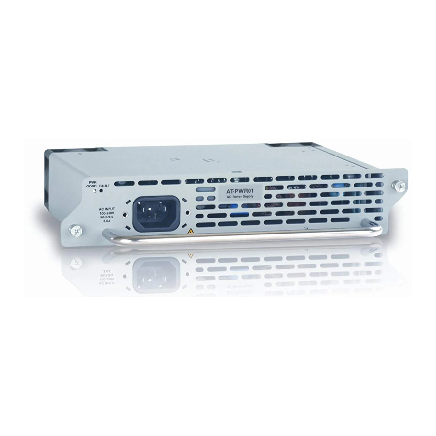
AT-8900 Series Hardware Reference Printed Models Covered By This Guide This Quick Install Guide includes information on the following models: AT-PWR01 (AC power supply unit) AT-PWR01 (DC power supply unit) AT-FAN01 (fan only module) Package Contents AT-8900 Series switches are supplied with a single power supply unit (PSU), either AC or DC, and a fan only module (FOM) pre-installed at factory as standard. - Page 4 All AC and DC versions of this equipment must be earthed. Follow these steps to install a PSU: Read the safety information The AT-PWR01 Safety and Statutory Information booklet includes all relevant safety information. A copy of this booklet is supplied with the PSU, and can also be downloaded from www.alliedtelesyn.co.nz/support/at8900/.
- Page 5 Loosen the two Phillips screws on the PSU or FOM until the screws disengage from the switch chassis (see Figure 1). Figure 1: Captive mounting screws on the AT-PWR01 and AT-FAN01 Captive screw Slowly and carefully slide the PSU or FOM out of the switch’s power supply bay.
- Page 6 Apply power to the PSU For AC Models: Read the AT-PWR01 Safety and Statutory Information booklet before connecting a PSU to an external AC power source. A copy of the safety booklet is included with each PSU. Plug the provided AC power cord into the AC power inlet on the rear panel of the PSU and connect the PSU to the mains power supply.
- Page 7 Quick Install Guide Check that the PSU terminals are wired to the correct polarity. A PSU will be damaged if incorrectly connected. The transparent plastic terminal cover must be replaced. 10. Switch the power switch to the ON position. Check the PSU LEDs Each PSU has LEDs that indicate the PSU’s operational status.
- Page 8 75º C (167º F). A FOM is installed in the switch and a fan has failed. The bay is empty (no PSU or FOM installed). Not lit A FOM is installed and the fan is good. AT-PWR01 & AT-PWR01-80 C613-04049-01 REV B...
-
Page 9: Where To Find More Information
Quick Install Guide Where to Find More Information Sources of further information: The AT-PWR01 Statutory and Safety Information booklet, which provides safety and statutory information for the power supply units. The AT-8900 Series Statutory and Safety Information booklet, which provides important safety information and statutory declarations for AT-8900 Series switches.
Need help?
Do you have a question about the AT-PWR01 and is the answer not in the manual?
Questions and answers