Allied Telesis AT-PWR01 Installation Manual
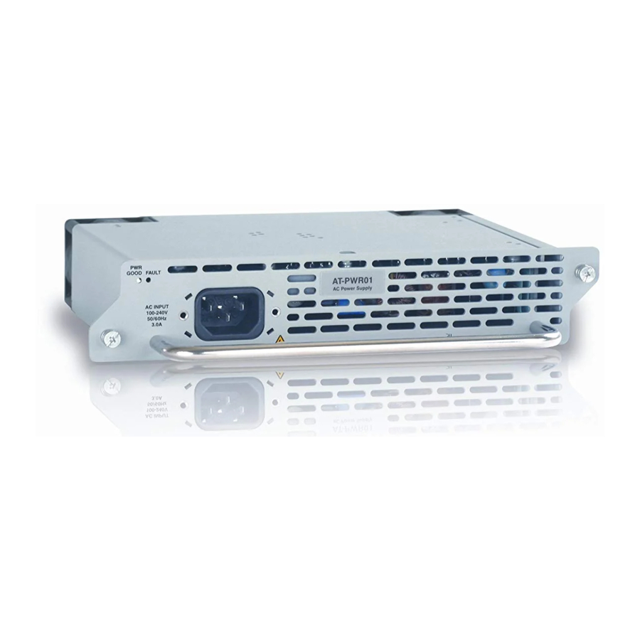
Removable power supply and fan
Hide thumbs
Also See for AT-PWR01:
- Installation manual (21 pages) ,
- Quick install manual (9 pages) ,
- Installation manual (27 pages)
Table of Contents
Advertisement
Quick Links
Download this manual
See also:
Installation Manual
Advertisement
Table of Contents

Subscribe to Our Youtube Channel
Related Manuals for Allied Telesis AT-PWR01


Summary of Contents for Allied Telesis AT-PWR01
- Page 1 Removable Power Supply and Fan Installation Guide AT-PWR01 AT-PWR02 AT-PWR05 AT-FAN01 AT-FAN03...
-
Page 2: Installation Guide
Removable Power Supply and Fan Installation Guide AT-PWR01 AT-PWR02 AT-PWR05 AT-FAN01 AT-FAN03 Download the complete document set from www.alliedtelesis.com/support/software... - Page 3 Removable Power Supply and Fan Installation Guide Document Number C613-04057-00 REV M © 2008 Allied Telesis, Inc. All rights reserved. No part of this publication may be reproduced without prior written permission from Allied Telesis, Inc. Allied Telesis, Inc. reserves the right to change specifications and other information in this document without prior written notice.
-
Page 4: Table Of Contents
Installation Guide Contents About this Guide ......................4 Compatible Switches ....................... 4 Package Contents ......................5 Installing a Power Supply Unit or Fan ................6 Connecting an AC power supply .................. 9 Connecting a DC power supply .................. 11 Checking LEDs ........................ 12 Removing a Power Supply Unit or Fan .............. -
Page 5: About This Guide
Removable Power Supply and Fan About this Guide This Installation Guide describes how to install the following PSUs and fans: ■ AT-PWR01 PSU, either AC or DC power supply unit ■ AT-PWR02 PSU, AC only ■ AT-PWR05 PSU, AC only ■... -
Page 6: Package Contents
PSUs. The following items are included with each factory-installed PSU. Contact your authorised Allied Telesis distributor or reseller if any are damaged or missing. ■ one AC power cord (AC models) ■... -
Page 7: Installing A Power Supply Unit Or Fan
Caution Follow correct anti-static procedures. Failure to do so could damage the PSU, fan, or switch. If you are unsure about correct procedures, contact your authorised Allied Telesis distributor or reseller. Caution When adding or replacing power supplies, keep your hands and fingers out of the power supply bays. - Page 8 Installation Guide Installing a PWR01, PWR02, or FAN01 If there is a PSU, fan or blanking plate in the bay you wish to install the unit, first remove the old unit, following the steps described in section “Removing a Power Supply Unit or Fan” on page Insert the new PSU or fan unit, and carefully slide it into the bay.
- Page 9 Removable Power Supply and Fan Installing a PWR05 or FAN03 If there is a PSU, fan or blanking plate in the bay you wish to install the unit, first remove the old unit, following the steps described in section “Removing a Power Supply Unit or Fan” on page PSU bays Service access...
-
Page 10: Connecting An Ac Power Supply
Follow these instructions to connect an AT-PWR01, AT-PWR02, or AT-PWR05 AC PSU to an AC power supply: Warning The AT-PWR01 AC PSU has a fuse rating of 250V, 5A for FH101 and FH102. Warning The AT-PWR01 AC PSU has double pole/neutral fusing. Electric shock is possible since there are dual primary fuses, one on the phase circuit and one on the neutral circuit. - Page 11 Removable Power Supply and Fan Ferrite core Looped power cord Plug the AC power cord into the power inlet on the PSU. Connect the power cord to the main power source. Check that the Run/Standby switch is set to the Run position (1). Both the AC and DC LEDs should be lit.
-
Page 12: Connecting A Dc Power Supply
Installation Guide Connecting a DC power supply Follow these instructions to connect an AT-PWR01 DC PSU to a DC power supply. Only trained and qualified personnel should connect a DC power supply. You need an appropriate DC power source, DC supply cable, ring connectors, a crimp tool and an appropriate screwdriver to tighten the terminal screws. -
Page 13: Checking Leds
Removable Power Supply and Fan Ensure there are no exposed cable strands. Replace the cover. You must replace the transparent plastic terminal cover before continuing. Secure the supply cable to the rack framework or a similar object to ensure that connections are isolated from any force applied to the cable. Ensure the circuit breaker for the supply circuit and the Run/Standby switch on the PSU are off. - Page 14 Installation Guide PWR05 The following table describes LEDs on the PWR05 power supply unit. State Description Green AC input voltage is within 90-264VAC, 47-63Hz. AC input voltage is outside the acceptable range. Green AC output voltage is within 12V +/- 10%. AC output voltage is outside the acceptable range.
- Page 15 Removable Power Supply and Fan Switch The following table describes how LEDs on the switch report operations and faults with installed PSUs and FOMs. State Description PSU 1 Green The PSU is installed and supplying power to the switch. The voltage output is within specification. PSU 2 One of the following: The PSU is installed in the switch, and a fan has...
-
Page 16: Removing A Power Supply Unit Or Fan
Caution Follow correct anti-static procedures. Failure to do so could damage the PSU, fan, or switch. If you are unsure about correct procedures, contact your authorised Allied Telesis distributor or reseller. Caution Keep your hands and fingers out of the power supply bays. - Page 17 Removable Power Supply and Fan Switch Captive screw Captive screw The following is a diagram of PWR05 and FAN03 PSU bays Service access panels Chassis fan Captive screw Captive screw Remove the PSU, chassis fan module, FOM or the blanking plate from the switch.
- Page 18 Installation Guide Avoid the spinning blades on FAN03. Contact may cause personal injury or damage the unit. Do not operate the switch for extended periods without functioning chassis fan modules. Doing so will cause the switch to overheat and shut down, and may damage the switch.
-
Page 19: Troubleshooting
Removable Power Supply and Fan Troubleshooting If the PSU does not function as expected: ■ Check that all cable connections are correct and secure. ■ On the PWR01 DC model, check that the Run/Standby switch has been pressed and is in the On position. ■... -
Page 20: Obtaining Documentation And Resources
You can download it from www.adobe.com. Other resources How-To Notes describe a range of standard Allied Telesis solutions, and include technical tips and guides to configuring specific hardware and software features. You can download the latest How-To Notes from www.alliedtelesis.com/resources/literature/howto.aspx. - Page 21 Contacting us With locations covering all of the established markets in North America, Latin America, Europe, Asia, and the Pacific, Allied Telesis provides localized sales and technical support worldwide. To find the representative nearest you, visit us on the Web at www.alliedtelesis.com.
-
Page 22: Standards
Installation Guide Standards Where applicable, the products in this document meet the following standards: Category Approval Agency and Requirement Safety UL60950-1 EN 60825-1 CAN/CSA-C22.2 No. 60950-1-03 EN 60825-2 EN60950-1 21 CFR 1040 AS/NZS 60950.1 Electromagnetic FCC CFR47 Part 15 Class A CNS 13438 Class A EN55022 Class A EN61000-3-2/3... -
Page 23: Ec Declaration Of Conformity
ALLIED TELESIS LABS LIMITED 27 NAZARETH AVENUE CHRISTCHURCH 8024 NEW ZEALAND Declare under our sole legal responsibility that these products: AT-PWR01, AT-PWR01-80, AT-PWR02, and AT-PWR05 Power Supply Units Are in conformity with the essential requirements of directives: ■ 2006/95/EC Low Voltage Directive ■...
Need help?
Do you have a question about the AT-PWR01 and is the answer not in the manual?
Questions and answers