Electro-Voice System Controller NetMax N8000 Owner's Manual
Electro-voice netmax system controller owner's manual
Hide thumbs
Also See for System Controller NetMax N8000:
- Specifications (4 pages) ,
- Brochure (6 pages)
Table of Contents
Advertisement
Advertisement
Table of Contents

Related Manuals for Electro-Voice System Controller NetMax N8000

Summary of Contents for Electro-Voice System Controller NetMax N8000
- Page 1 OWNER’S MANUAL...
-
Page 2: Table Of Contents
Introduction ............5 Description of the system . -
Page 3: Important Safety Instructions
Read these instructions. Keep these instructions. Heed all warnings. Follow all instructions. Do not use this apparatus near water. Clean only with a dry cloth. Do not block any ventilation openings. Install in accordance with the manufacture’s instructions. Do not install near heat sources such as radiators, heat registers, stoves, or other apparatus (including amplifiers) that produce heat. Do not defeat the safety purpose of the polarized or the grounding-type plug. - Page 4 HF-Interference This equipment has been tested and found to comply with the limits for a Class B digital device, pursuant to Part 15 of the FCC Rules. These limits are designed to provide reasonable protection agains harmful interference in a residential installation. This equipment generates, uses and can radiate radio frequency energy and, if not installed and used in accordance with the instructions, may cause harmful interference to radio communications.
-
Page 5: Introduction
N8000 can be connected via a CobraNet™ audio and control network so that a large, decentralized audio system can be assembled. NetMax also manages the Electro-Voice P-series remote amplifiers including its speaker and system monitoring functions. The connection is directly effected via CAN to the N8000. -
Page 6: N8000 Features
1.2 N8000 features NetMax N8000 is an all-purpose digital audio system controller with outstanding performance features. A high quality system design provides excellent audio quality and clear sound, which is achieved by the application of high-end 24 Bit A/D and D/A converters with 120 dB volume range, high-quality input and output circuits in the analog domain and digital signal processing with optimized 48 bit double-precision algorithms. -
Page 7: Unpacking And Warranty
AMX™. For that, an open interface protocol is available. The remote CAN-bus serves as connection to Electro-Voice remote amplifiers. Up to 100 amplifiers can be attached via CAN to one single N8000. Together with additional N8000s and amplifiers they can also be integrated in a complex and powerful audio system. -
Page 8: Installation Instruction
PC and the N8000 has been established via Ethernet, the configuration can be transmitted to it. In addition to configurations, IRIS-Net can also be used for extensive supervision, control and monitoring of N8000 system controllers (and Electro-Voice Precision Series Remote Amplifiers which are connected to them). -
Page 9: Browser Interface
Introduction 1.6 Browser Interface Some of the configuration and operation options of the N8000 which are available in IRIS-Net are also provided by the N8000 browser interface. Any standard Internet browser with activated JavaScript and CSS can be utilized in order to use the browser interface. Please find the detailed information on the N8000 browser interface in the file N8000 browser manual in the IRIS-Net setup directory (\Documentation\NetMax). -
Page 10: Control Elements And Connections
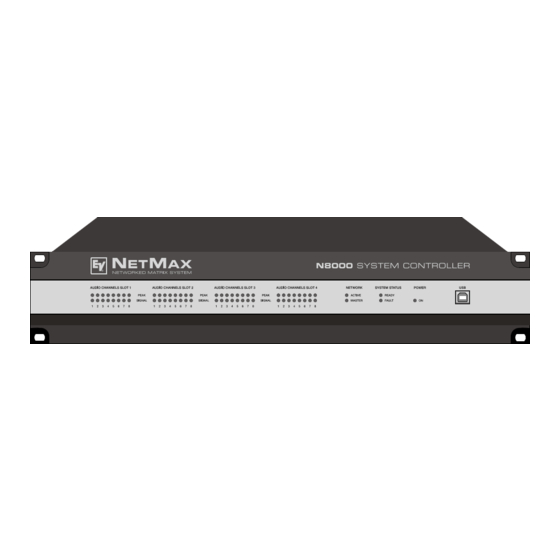
2 Control Elements and Connections 2.1 Front Faceplate The front faceplate of the N8000 has level and status displays and it offers also the possibility to connect a PC via a USB interface. SIGNAL / PEAK-LEDs exist for all 32 audio channels. The channels are combined to groups of 8 and assigned to the audio-slots 1 to 4 at the rear. -
Page 11: System Status-Leds
clock master breaks down or is removed from the network, another N8000 will take over this function automatically. SYSTEM STATUS-LEDs can be specified which errors should be displayed. If the FAULT display is on, the error should be identified promptly. This can be done using the detailed diagnostics within the IRIS-Net PC software. -
Page 12: Rear Panel
2.2 Rear Panel N8000 MODEL: BURNSVILLE, MN, U.S.A. MADE IN GERMANY 100-240 V~ 50-60 Hz/ 90 W N378 SERIAL: 170323 03150 10001 CONTROL PORT INPUTS 10V REF 0-10V RELAY OUTPUTS 5V/200mA There are all connections for analog and digital audio signals, control interfaces and the power supply at the rear panel of the N8000. -
Page 13: Ethernet Interface
A PC can also be connected to the RS-232 port to access N8000 parameters using a terminal program Electro-Voice remote amplifiers and other devices with CAN interfaces can be connected to the N8000 via the CAN interface. Up to 100 remote amplifiers can be connected with a single N8000. -
Page 14: Control Port
seconds. The duration of the flashing within these 2 seconds depends on the bus load. The higher the bus load is the longer the duration of the flashing within these two seconds will be. CONTROL PORT software. Examples of use are: power on/standby switching, preset switching or parameter control. -
Page 15: Preparations
3 Preparations 3.1 Mounting 1. Install the expansion cards. If you have purchased expansion cards (AI-1, AO-1, CM-1, DSP-1, etc.) for your N8000 system controller, please install them. In this regard, please note the paragraph page 15 as well as the installation instructions in the manuals which are enclosed to the expansion cards. 2. -
Page 16: System Expansion With Analog/Digital Inputs Or Outputs
• 1 DSP expansion module (DSP-1) for the expansion of the storage capacity and signal pro- cessing ATTENTION: It is essential to switch off the N8000 if you want to install or change a module. You will find detailed instructions in the data sheet of the corresponding module. System expansion with analog/digital inputs or outputs There are four slots at the rear of the N8000 which are intended to expand the systems with analogue or digital inputs or outputs. -
Page 17: Interface Description
3.3 Interface description Ethernet Interface By connecting the N8000 system controller via the Ethernet interface, the communication between the N8000 and one or several PC is possible. This allows the configuration of N8000 via IRIS-Net software. Furthermore, the whole connected system (consisting of N8000s and EV Precision Series Remote Control Amplifiers) can be operated and monitored. -
Page 18: Can Interface
CAN Interface The network for the Electro-Voice remote power amplifiers is based on the CAN-bus standard, which has become widely accepted in the automotive, industrial and security sector and which has proved itself for years. The CAN-bus is a balanced serial interface to transmit commands and data. - Page 19 MONITOR BUS + MONITOR BUS - The CAN-bus makes it possible to use different data transmission rates, in which the boud rate is indirectly proportional to the length of the bus. If the network is only slightly extended, higher baud rates up to 500 kbit/s are possible. In case of larger extensions, the baud rate has to be lowered (to a min.
-
Page 20: Usb Connection
USB connection The USB interface on the front panel of the N8000 uses the USB 1.1 standard. Accordingly, the low speed (1,5 MBit/s) and full speed (12 MBit/s) transfer rates are supported. According to USB specifications, the cable which is connected to this interface must not be longer than 5 meters. -
Page 21: Control Port
The pins of the RS-232 interface used in the N8000 are indicated in the following illustration and table. Connections which are not given are internally connected in the N8000 so that the communication between the N8000 and the connected device is possible via a software handshake system. - Page 22 The following figure shows an example application for the "analogue circuit" on the control inputs of the N8000. A voltage which can be changed via a potentiometer is connected at the control input 1. The N8000 can be configured via IRIS-Net so that this voltage can be used to adjust a variable parameter, for example, adjusting the volume of an audio input or output.
-
Page 23: Audio Interfaces
ATTENTION: The maximum allowable current at the 5 V output is 200 mA. The two left connections of the RELAY OUTPUTS are the READY/FAULT output of the N8000. This floating output is closed when the N8000 is ready for operation and no error has occurred. It is possible in IRIS-Net to configure which kind of error causes the contact to be opened. - Page 24 N8000 Analog audio output cable, XLR (male) on Phoenix Digital audio connecting cable It is advisable to choose balanced cables (2 signal conductors + shield) with XLR connectors as digital audio connections. Although all N8000 digital audio inputs can be used unbalanced, balanced audio cable is the better choice.
-
Page 25: Network Configuration
4 Network configuration 4.1 Introduction The N8000 system controller can be connected to a TCP/IP-network via the Ethernet interface at its rear panel (see page 13). For further information on the principles of Ethernet and TCP/IP please see the chapter Ethernet principles on page 33 in the appendix of this document. The N8000 comes with the following network configurations from the factory: An IP address must be unique, it must only be allocated to one single device (host) in a network. - Page 26 IP address 192.168.1.100 would exist four times in the network. Because of this, the preset IP address of three NetMax N8000s must be replaced with a unique address. It is advantageous and strongly recommended to list all devices used in the Ethernet network and IP addresses for changing the preset IP addresses of the N8000s.
-
Page 27: Configuration
4.2 Configuration Configuration and testing of an Ethernet connection with N8000 The purpose of this procedure is to build a connection between a PC and a N8000 with factory network settings (see page 25) via Ethernet and to check the proper function of this connection. In the following it is assumed that neither the PC nor the N8000 are connected with an existing network. - Page 28 3. Click on Properties in the context menu. The pop-up window Local Area Connection Properties appears. 4. Double click on Internet Protocol (TCP/IP). The pop-up window Internet Protocol (TCP/IP) Properties appears. 5. Choose the option Use the following IP address in the window. 6.
- Page 29 8. Close the window Internet Protocol (TCP/IP) Properties by clicking on the OK button. The IP configuration of the PC is now complete. In the following steps the connection of the PC with the N8000 will be established and checked. 9.
- Page 30 12. Enter ping 192.168.1.100 and tap the return button. The PC is now checking the connection with the N8000. For this four network packets are sent to the N8000 via Ethernet then the N8000 has to confirm these packets. If the Ethernet connection is successful, no packets get lost.
-
Page 31: Appendix
Four microphones, one CD player and one tuner are the connected signal sources. Both active and passive speakers are used for the sound reinforcement. The Electro-Voice Precision Series Remote Amplifiers which are used for the operation of the passive speakers are connected with the N8000 via the CAN Bus in addition to the audio connections. -
Page 32: Troubleshootings
5.2 Troubleshootings Problem: It is not possible to establish a connection with the N8000 via IRIS-Net. Switch on N8000 N8000 online? Problem solved NetMax N8000 System Controller Owner’s manual Host not reachable (Timeout) N8000 activated? IP address in IRIS correct? Correct IP address PING to IP address... -
Page 33: Ethernet Principles
Check Network Configuration of PC: Check the network configuration of the used PC. Remember that the network part of the used IP addresses that is used and the subnet mask of the PC and the N8000 have to be identical. Ruling Out Duplicate IP-Adresses: It is possible that the same IP address is allocated twice if there are more devices in an Ethernet network and if the IP addresses are allocated manually. -
Page 34: Ip Addresses
• 100Base-TX (IEEE 802.3u): Two twisted wire pairs are used for the connection (see above). However, in this case, a CAT-5 cable has to be used. 100Base-TX has a transfer rate of 100 MBit/s and is the standard Ethernet implementation nowadays. IP addresses Diverse network protocols can be used for the communication of the devices connected to the Ethernet network. -
Page 35: Automatic/Manual Allocation Of Ip Addresses
Appendix For example, a network could e.g. split the 4 Byte (32 bit) of an IP address in a 3 Byte long network part and in 1 Byte long host part. The exact partitioning between network part and host part is given in the form of subnet masks. In this case, the partitioning of the first 24 bits or the last 8 bits would be made because of the subnet mask 255.255.255.0. -
Page 36: Can-Bus Principles
5.4 CAN-Bus Principles The network topology used by the CAN bus is based on the so-called “bus or line topology”, i.e. all participants are connected via a single two-wire cable (Twisted-Pair cable, shielded or unshielded) with the cabling running from one participant on the bus to the next, allowing unlimited communication among all devices. - Page 37 Appendix bus signals. The internal running time of the repeaters of approx. 150 ns corresponds to an extension of the bus over approx. 45 meters. • Creation of alternative network topologies By using one or several repeaters, not only the above-mentioned bus topology, but the creation of other network topologies are also possible.
-
Page 38: System Examples
System Examples The following illustrations show examples of the data-bus wiring for different sizes of CAN-bus networks.. System with 5 power amps and 1 N8000 at the beginning of the bus. Termina- tion plugs at the N8000 (first unit on the bus) and at amp 5 (last unit on the bus). System with 2 amp-racks and 1 N8000/PC in the middle. -
Page 39: Performance Specifications
Performance Specifications According to the ISO 11898-2 standard, CAN-bus data transfer cabling has to be carried out using Twisted-Pair cables with or without shielding providing a characteristic impedance of 120 Ω. Both ends of a CAN-bus need to be terminated with 120 Ω termination-plugs. The maximum bus-length depends on the actual data transfer rate, the kind of data transfer cable being used, as well as the total number of participants on the bus. -
Page 40: Ip Address Table
5.5 IP Address Table Project: _________________________________ Device IRIS-Net Device Name NetMax N8000 System Controller Owner’s manual Subnet mask Gateway Location / Description IP Address... -
Page 41: Specifications/Technische Daten
6.1 Specifications/Technische Daten GENERAL DESCRIPTION AND FEATURES N8000 System Controller Audio Networking Safety / Redundancy PC Configuration and Control Software AUDIO SPECIFICATIONS Audio Inputs - Analog Input Module AI-1 Connectors Input Level (nominal) Input Level (max. before clip) Input Impedance Common Mode Rejection A/D Conversion Audio Outputs - Analog Output Module AO-1 8 analog audio outputs per module, line level, electronically... -
Page 42: Signal Processing
SIGNAL PROCESSING Sample Rate Data Format Signal Processing INTERFACES Ethernet RS-232 GPIO Control Port N8000 GENERAL SPECIFICATIONS Power Supply Power Consumption Safety Class Cooling Operating Temperature Range Dimensions (W x H x D) Weight MODULES / OPTIONS AI-1 Analog Input Module AO-1 Analog Output Module CM-1 CobraNet™... -
Page 43: Block Diagram/Blockschaltbild
6.2 Block Diagram/Blockschaltbild AUDIO MODULES AUDIO AUDIO SLOT 1 SLOT 2 Audio Out (4x8 Channels) Audio In (4x8 Channels) 12.288 MHz CLOCK CIRCUIT Clocks (MCLK, WCLK) 24 Bit DSP Bus DELAY SRAM Remote CAN Interface 2 x RJ-45 GPIO 12-pin 4 Analog Inputs Phoenix 3 Logic Outputs... -
Page 44: Dimensions/Abmessungen
6.3 Dimensions/Abmessungen NetMax N8000 System Controller Owner’s manual / Bedienungsanleitung... - Page 45 Notes...
- Page 46 Notes...
- Page 47 Notes...
- Page 48 France: EVI Audio France, Parc de Courcerin, Allée Lech Walesa, 77185 Lognes, France, Tél : +33 1 6480 0090, FAX: +33 1 6006 5103 Subject to change withou prior notice. Printed in Germany V1.2 5/18/06 / D 362 478 www.electro-voice.de...
Need help?
Do you have a question about the System Controller NetMax N8000 and is the answer not in the manual?
Questions and answers