
Subscribe to Our Youtube Channel
Related Manuals for ASROCK G41MH/USB3 R2.0


Summary of Contents for ASROCK G41MH/USB3 R2.0
-
Page 1: User Manual
G41MH/USB3 R2.0 User Manual Version 1.0 Published May 2011 Copyright©2011 ASRock INC. All rights reserved. 1 1 1 1 1... - Page 2 (including damages for loss of profits, loss of business, loss of data, interruption of business and the like), even if ASRock has been advised of the possibility of such damages arising from any defect or error in the manual or product.
-
Page 3: Table Of Contents
Contents Contents Contents Contents Contents 1 Introduction 1 Introduction ........... 1 Introduction ...................... 5 5 5 5 5 ........... 1 Introduction 1 Introduction ........... 1.1 Package Contents ............5 1.2 Specifications ..............6 1.3 Motherboard Layout ............11 1.4 I/O Panel ................. 12 2 Installation 2 Installation 2 Installation ............. - Page 4 3.7 Security Screen ............53 3.8 Exit Screen ..............54 4 Software Support 4 Software Support 4 Software Support ........... 4 Software Support 4 Software Support .................................... 55 4.1 Install Operating System ..........55 4.2 Support CD Information ..........55 4.2.1 Running Support CD ..........
-
Page 5: Introduction
In case any modifications of this manual occur, the updated version will be available on ASRock website without further notice. You may find the latest VGA cards and CPU support lists on ASRock website as well. ASRock website http://www.asrock.com If you require technical support related to this motherboard, please visit our website for specific information about the model you are using. -
Page 6: Specifications
Specifications Specifications Specifications Specifications Specifications Platform - Micro ATX Form Factor: 9.6-in x 8.4-in, 24.4 cm x 21.3 cm - Solid Capacitor for CPU power ® - LGA 775 for Intel Core 2 Extreme / Core 2 Quad / Core ®... - Page 7 DVD Suite - OEM and Trial; Creative Sound Blaster X-Fi MB - Trial) Unique Feature - ASRock OC Tuner (see CAUTION 8) - ASRock Intelligent Energy Saver (see CAUTION 9) - ASRock Instant Boot - ASRock Instant Flash (see CAUTION 10) - ASRock OC DNA (see CAUTION 11)
- Page 8 - FCC, CE, WHQL - ErP/EuP Ready (ErP/EuP ready power supply is required) (see CAUTION 17) * For detailed product information, please visit our website: http://www.asrock.com WARNING Please realize that there is a certain risk involved with overclocking, including adjusting the setting in the BIOS, applying Untied Overclocking Technology, or using the third- party overclocking tools.
- Page 9 Intelligent Energy Saver. ASRock website: http://www.asrock.com 10. ASRock Instant Flash is a BIOS flash utility embedded in Flash ROM. This convenient BIOS update tool allows you to update system BIOS without entering operating systems first like MS-DOS or Windows ®...
- Page 10 64 bit, and your browser version is IE8. ASRock website: http://www.asrock.com/Feature/SmartView/index.asp 14. ASRock XFast USB can boost USB storage device performance. The performance may depend on the property of the device. 15. Although this motherboard offers stepless control, it is not recommended to perform over-clocking.
-
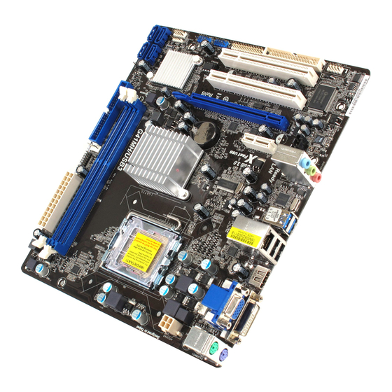
Page 11: Motherboard Layout
Motherboard Layout Motherboard Layout Motherboard Layout Motherboard Layout Motherboard Layout 21.3cm (8.4 in) Designed in Taipei CPU_FAN1 PWR_FAN1 USB 2.0 Top: T: USB0 RJ-45 B: USB1 USB 3.0 T: USB2 Intel B: USB3 CHA_FAN1 Chipset HD_AUDIO1 USB 3.0 CMOS Battery PCIE1 IDE1 PCIE2... -
Page 12: I/O Panel
I/O Panel I/O Panel I/O Panel I/O Panel I/O Panel PS/2 Mouse Port (Green *** 7 USB 3.0 Ports (USB23) VGA/D-Sub Port USB 2.0 Ports (USB01) LAN RJ-45 Port HDMI Port Line In (Light Blue) VGA/DVI-D Port ** 5 Front Speaker (Lime) PS/2 Keyboard Port (Purple) Microphone (Pink) * There are two LED next to the LAN port. -
Page 13: Installation
Chapter 2: Installation Chapter 2: Installation Chapter 2: Installation Chapter 2: Installation Chapter 2: Installation This is a Micro ATX form factor (9.6" x 8.4", 24.4 x 21.3 cm) motherboard. Before you install the motherboard, study the configuration of your chassis to ensure that the motherboard fits into it. -
Page 14: Cpu Installation
2.3 CPU Installation 2.3 CPU Installation 2.3 CPU Installation 2.3 CPU Installation 2.3 CPU Installation For the installation of Intel 775-LAND CPU, please follow the steps below. 775-Pin Socket Overview Before you insert the 775-LAND CPU into the socket, please check if the CPU surface is unclean or if there is any bent pin on the socket. - Page 15 For proper inserting, please ensure to match the two orientation key notches of the CPU with the two alignment keys of the socket. Step 2-3. Carefully place the CPU into the socket by using a purely vertical motion. Step 2-4. Verify that the CPU is within the socket and properly mated to the orient keys.
-
Page 16: Installation Of Heatsink And Cpu Fan
Installation of CPU Fan and Heatsink Installation of CPU Fan and Heatsink Installation of CPU Fan and Heatsink Installation of CPU Fan and Heatsink Installation of CPU Fan and Heatsink This motherboard is equipped with 775-Pin socket that supports Intel 775-LAND CPU. Please adopt the type of heatsink and cooling fan compliant with Intel 775-LAND CPU to dissipate heat. -
Page 17: Installation Of Memory Modules (Dimm)
2.5 Installation of Memory Modules (DIMM) 2.5 Installation of Memory Modules (DIMM) G41MH/USB3 R2.0 motherboard provides two 240-pin DDR3 (Double Data Rate 3) DIMM slots, and supports Dual Channel Memory Technology. For dual channel configuration, you always need to install two identical (the same brand, speed, size and chip-type) memory modules in the DDR3 DIMM slots to activate Dual Channel Memory Technology. -
Page 18: Expansion Slots (Pci And Pci Express Slots)
2.6 Expansion Slots (PCI and PCI Express Slots) 2.6 Expansion Slots (PCI and PCI Express Slots) 2.6 Expansion Slots (PCI and PCI Express Slots) 2.6 Expansion Slots (PCI and PCI Express Slots) 2.6 Expansion Slots (PCI and PCI Express Slots) There are 2 PCI slots and 2 PCI Express slots on this motherboard. -
Page 19: Dual Monitor Feature
2.7 Dual Monitor Feature 2.7 Dual Monitor Feature 2.7 Dual Monitor Feature 2.7 Dual Monitor Feature 2.7 Dual Monitor Feature This motherboard supports dual monitor feature. With the internal VGA output support (DVI-D, D-Sub and HDMI), you can easily enjoy the benefits of dual monitor feature without installing any add-on VGA card to this motherboard. - Page 20 3. Set up a dual-monitor display. ® For Windows XP / XP 64-bit OS: Right click the desktop, choose “Properties”, and select the “Settings” tab so that you can adjust the parameters of the dual-monitor according to the steps below. A.
- Page 21 HDCP Function HDCP function is supported on this motherboard. To use HDCP function with this motherboard, you need to adopt the monitor that supports HDCP function as well. Therefore, you can enjoy the superior display quality with high-definition HDCP encryption contents.
-
Page 22: Jumpers Setup
2.8 Jumpers Setup 2.8 Jumpers Setup 2.8 Jumpers Setup 2.8 Jumpers Setup 2.8 Jumpers Setup The illustration shows how jumpers are setup. When the jumper cap is placed on pins, the jumper is “Short”. If no jumper cap is placed on pins, the jumper is “Open”. The il- lustration shows a 3-pin jumper whose pin1 and pin2 are “Short”... -
Page 23: Onboard Headers And Connectors
2.9 Onboard Headers and Connectors 2.9 Onboard Headers and Connectors 2.9 Onboard Headers and Connectors 2.9 Onboard Headers and Connectors 2.9 Onboard Headers and Connectors Onboard headers and connectors are NOT jumpers. Do NOT place jumper caps over these headers and connectors. Placing jumper caps over the headers and connectors will cause permanent damage of the motherboard! FDD connector... - Page 24 USB 2.0 Headers Besides two default USB 2.0 USB_PWR ports on the I/O panel, there are (9-pin USB6_7) DUMMY two USB 2.0 headers on this (see p.11 No. 19) motherboard. Each USB 2.0 header can support two USB USB_PWR 2.0 ports. (9-pin USB4_5) USB_PWR (see p.11 No.
- Page 25 Front Panel Audio Header This is an interface for front PRESENCE# MIC_RET panel audio cable that allows (9-pin HD_AUDIO1) OUT_RET convenient connection and (see p.11 No. 29) control of audio devices. OUT2_L J_SENSE OUT2_R MIC2_R MIC2_L 1. High Definition Audio supports Jack Sensing, but the panel wire on the chassis must support HDA to function correctly.
- Page 26 Though this motherboard provides 4-Pin CPU fan (Quiet Fan) support, the 3-Pin CPU fan still can work successfully even without the fan speed control function. If you plan to connect the 3-Pin CPU fan to the CPU fan connector on this motherboard, please connect it to Pin 1-3.
-
Page 27: Sataii Hard Disk Setup Guide
2.10 SA 2.10 SA 2.10 SAT T T T T AII Hard Disk Setup Guide AII Hard Disk Setup Guide AII Hard Disk Setup Guide AII Hard Disk Setup Guide 2.10 SA 2.10 SA AII Hard Disk Setup Guide Before installing SATAII hard disk to your computer, please carefully read below SATAII hard disk setup guide. -
Page 28: Installation
2.11 2.11 Serial A 2.11 Serial A Serial A Serial AT T T T T A (SA A (SA A (SAT T T T T A) / Serial A A (SA A) / Serial A A) / Serial AT T T T T AII (SA A) / Serial A AII (SA AII (SAT T T T T AII) Hard Disks... -
Page 29: Bios Setup Utility
Chapter 3 BIOS SETUP UTILITY Chapter 3 BIOS SETUP UTILITY Chapter 3 BIOS SETUP UTILITY Chapter 3 BIOS SETUP UTILITY Chapter 3 BIOS SETUP UTILITY 3.1 Introduction 3.1 Introduction 3.1 Introduction 3.1 Introduction 3.1 Introduction This section explains how to use the BIOS SETUP UTILITY to configure your system. The SPI Memory on the motherboard stores the BIOS SETUP UTILITY. -
Page 30: Navigation Keys
3.1.2 3.1.2 Navigation Keys 3.1.2 Navigation Keys Navigation Keys Navigation Keys 3.1.2 3.1.2 Navigation Keys Please check the following table for the function description of each navigation key. Navigation Key(s) Function Description Moves cursor left or right to select Screens Moves cursor up or down to select items + / - To change option for the selected items... -
Page 31: Oc Tweaker Screen
3.3 OC T OC T OC T OC Tweak weak weak weaker Screen er Screen er Screen er Screen OC T weak er Screen In the OC Tweaker screen, you can set up overclocking features. BIOS SETUP UTILITY Main OC Tweaker Advanced H/W Monitor Boot... - Page 32 DRAM Timing Configuration BIOS SETUP UTILITY OC Tweaker DRAM Timing Control DRAM tCL Value [Auto] DRAM tCL [Auto] DRAM tRCD Min = 5 DRAM tRP [Auto] Max = 10 DRAM tRAS [Auto] DRAM tRFC [Auto] DRAM tWR [Auto] [Auto] DRAM tWTR DRAM tRRD [Auto] DRAM tRTP...
- Page 33 Ratio Status This is a read-only item, which displays whether the ratio status of this motherboard is “Locked” or “Unlocked”. If it shows “Unlocked”, you will find an item Ratio CMOS Setting appears to allow you changing the ratio value of this motherboard. Ratio CMOS Setting If the ratio status is unlocked, you will find this item appear to allow you changing the ratio value of this motherboard.
- Page 34 DRAM Voltage Use this to select DRAM Voltage. The default value of this feature is [Auto]. NB Voltage Use this to select NB Voltage. The default value of this feature is [Auto]. SB Voltage Use this to select SB Voltage. The default value of this feature is [Auto]. VTT Voltage Use this to select VTT Voltage.
-
Page 35: Advanced Screen
Setting wrong values in this section may cause the system to malfunction. ASRock Instant Flash ASRock Instant Flash is a BIOS flash utility embedded in Flash ROM. This convenient BIOS update tool allows you to update system BIOS without entering operating systems first like MS-DOS or Windows ®... -
Page 36: Cpu Configuration
3.4.1 3.4.1 CPU Configuration 3.4.1 CPU Configuration CPU Configuration CPU Configuration 3.4.1 3.4.1 CPU Configuration BIOS SETUP UTILITY Advanced CPU Configuration Select the over clock mode. Overclock Mode [Auto] CPU Frequency (MHz) [200] PCIE Frequency (MHz) [100] [Enabled] Boot Failure Guard Boot Failure Guard Count Spread Spectrum [Auto]... - Page 37 EIST (Intel (R) SpeedStep(tm) tech.), and you plan to adjust the ratio value, please disable the option “ Intel (R) SpeedStep(tm) tech.” in advance. Enhance Halt State (C1E) All processors support the Halt State (C1). The C1 state is supported through the native processor instructions HLT and MWAIT and requires no hardware support from the chipset.
-
Page 38: Chipset Configuration
3.4.2 3.4.2 Chipset Configuration 3.4.2 Chipset Configuration Chipset Configuration Chipset Configuration 3.4.2 3.4.2 Chipset Configuration BIOS SETUP UTILITY Advanced Chipset Settings DRAM RCOMP and tRD Configuration DRAM DLL SKEW Configuration Fixed Mode Operation [Enabled] Intelligent Energy Saver [Disabled] Primary Graphics Adapter [PCI] Shared Memory [Auto]... - Page 39 DRAM CH0 G3 (Control2) This controls the number of DRAM CH0 G3 (Control2). Min: 1. Max: 15. The default value is [Auto]. DRAM CH0 G4 (Clocks1) This controls the number of DRAM CH0 G4 (Clocks1). Min: 1. Max: 15. The default value is [Auto].
- Page 40 DRAM DLL SKEW Configuration BIOS SETUP UTILITY Advanced DRAM DLL SKEW Settings DRAM CH0 CLKSET0 SKEW Info:0-0-0-0-0-0 [Auto] DRAM CH0 CLKSET0 SKEW DRAM CH0 CLKSET1 SKEW Info:0-0-0-0-0-0 [Auto] DRAM CH0 CLKSET1 SKEW DRAM CH0 CMD SKEW Info :0-0-0-0-0-0-0 [Auto] DRAM CH0 CMD SKEW DRAM CH0 CTRL0 SKEW Info :0-0-0-0-0-0-0 [Auto]...
- Page 41 DRAM CH1 CMD SKEW This controls the number of DRAM CH1 CMD SKEW. The default value is [Auto]. DRAM CH1 CTRL0 SKEW This controls the number of DRAM CH1 CTRL0 SKEW. The default value is [Auto]. DRAM CH1 CTRL1 SKEW This controls the number of DRAM CH1 CTRL1 SKEW.
- Page 42 DVMT Mode Select Use this option to adjust DVMT mode. The default value is [DVMT Mode]. DVMT (Dynamic Video Memory Technology) is an architecture that offers breakthrough performance for the motherboard through efficient memory utilization. In DVMT mode, the graphics driver allocates memory as needed for running graphics applications and is cooperatively using this memory ®...
-
Page 43: Acpi Configuration
3.4.3 3.4.3 3.4.3 ACPI Configuration 3.4.3 3.4.3 ACPI Configuration ACPI Configuration ACPI Configuration ACPI Configuration BIOS SETUP UTILITY Advanced ACPI Configuration Select auto-detect or disable the STR feature. Suspend To RAM [Auto] [Enabled] Check Ready Bit [Power Off] Restore on AC/Power Loss [Disabled] Ring-In Power On [Disabled]... -
Page 44: Storage Configuration
3.4.4 3.4.4 Storage Configuration 3.4.4 Storage Configuration Storage Configuration Storage Configuration 3.4.4 3.4.4 Storage Configuration BIOS SETUP UTILITY Advanced Set [Compatible] Storage Configuration when Legacy OS (MS-DOS, Win NT) ATA/IDE Configuration [Enhanced] device is used. Set [Enhanced] SATAII_1 [Hard Disk] when Native OS SATAII_2 [Not Detected]... - Page 45 Storage Device Configuration You may set the storage configuration for the device that you specify. We will use the “Primary IDE Master” as the example in the following instruction. BIOS SETUP UTILITY Advanced Primary IDE Master Select the type of device connected Device :Hard Disk to the system.
-
Page 46: Pcipnp Configuration
DMA Mode DMA capability allows the improved transfer-speed and data-integrity for compatible IDE devices. S.M.A.R.T. Use this item to enable or disable the S.M.A.R.T. (Self-Monitoring, Analysis, and Reporting Technology) feature. Configuration options: [Disabled], [Auto], [Enabled]. 32-Bit Data Transfer Use this item to enable 32-bit access to maximize the IDE hard disk data transfer rate. -
Page 47: Floppy Configuration
3.4.6 3.4.6 Floppy Configuration 3.4.6 Floppy Configuration Floppy Configuration Floppy Configuration 3.4.6 3.4.6 Floppy Configuration In this section, you may configure the type of your floppy drive. BIOS SETUP UTILITY Advanced Floppy Configuration Select the type of floppy drive connected to the [1.44 MB 3 "] Floppy A system. - Page 48 Parallel Port Address Use this item to set the address for the onboard parallel port or disable it. Configuration options: [Disabled], [378], and [278]. Parallel Port Mode Use this item to set the operation mode of the parallel port. The default value is [ECP+EPP].
-
Page 49: Usb Configuration
3.4.8 3.4.8 USB Configuration 3.4.8 USB Configuration USB Configuration USB Configuration 3.4.8 3.4.8 USB Configuration BIOS SETUP UTILITY Advanced USB Configuration To enable or disable the onboard USB controllers. [Enabled] USB Controller [Enabled] USB 2.0 Support Legacy USB Support [Enabled] USB 3.0 Controller [Enabled] USB Keyboard/Remote Power On... -
Page 50: Hardware Health Event Monitoring Screen
3.5 Hardware Health Event Monitoring Screen Hardware Health Event Monitoring Screen Hardware Health Event Monitoring Screen Hardware Health Event Monitoring Screen Hardware Health Event Monitoring Screen In this section, it allows you to monitor the status of the hardware on your system, including the parameters of the CPU temperature, motherboard temperature, CPU fan speed, chassis fan speed, and the critical voltage. - Page 51 Target M/B Temperature The target temperature will be between 45 C/113 F and 65 C/149 F. The default value is [50 C/122 F]. Target Fan Speed Use this option to set the target fan speed. You can freely adjust the target fan speed according to the target chassis temperature that you choose.
-
Page 52: Boot Screen
[Disabled]. The default value is [Enabled]. Boot Logo Use this option to select logo in POST screen. This option only appears when you enable the option “Full Screen Logo”. Configuration options: [Auto], [EuP], [Scenery] and [ASRock]. The default value is [Auto]. -
Page 53: Security Screen
Boot From Onboard LAN Use this item to enable or disable the Boot From Onboard LAN feature. Boot Up Num-Lock If this item is set to [On], it will automatically activate the Numeric Lock function after boot-up. Security Screen Security Screen 3.7 Security Screen Security Screen Security Screen... -
Page 54: Exit Screen
3.8 Exit Screen Exit Screen Exit Screen Exit Screen Exit Screen BIOS SETUP UTILITY Main OC Tweaker Advanced H/W Monitor Boot Security Exit Exit Options Exit system setup after saving the Save Changes and Exit changes. Discard Changes and Exit Discard Changes F10 key can be used for this operation. -
Page 55: Install Operating System
C o n t a c t I n f o r m a t i o n If you need to contact ASRock or want to know more about ASRock, welcome to visit ASRock’s website at http://www.asrock.com; or you may contact your...
Need help?
Do you have a question about the G41MH/USB3 R2.0 and is the answer not in the manual?
Questions and answers