Table of Contents
Advertisement
Copyright Notice:
Copyright Notice:
Copyright Notice:
Copyright Notice:
Copyright Notice:
No part of this installation guide may be reproduced, transcribed, transmitted, or trans-
lated in any language, in any form or by any means, except duplication of documen-
tation by the purchaser for backup purpose, without written consent of ASRock Inc.
Products and corporate names appearing in this guide may or may not be registered
trademarks or copyrights of their respective companies, and are used only for identifica-
tion or explanation and to the owners' benefit, without intent to infringe.
Disclaimer:
Disclaimer:
Disclaimer:
Disclaimer:
Disclaimer:
Specifications and information contained in this guide are furnished for informational
use only and subject to change without notice, and should not be constructed as a
commitment by ASRock. ASRock assumes no responsibility for any errors or omissions
that may appear in this guide.
With respect to the contents of this guide, ASRock does not provide warranty of any kind,
either expressed or implied, including but not limited to the implied warranties or
conditions of merchantability or fitness for a particular purpose. In no event shall
ASRock, its directors, officers, employees, or agents be liable for any indirect, special,
incidental, or consequential damages (including damages for loss of profits, loss of
business, loss of data, interruption of business and the like), even if ASRock has been
advised of the possibility of such damages arising from any defect or error in the guide
or product.
This device complies with Part 15 of the FCC Rules. Operation is subject to the
following two conditions:
(1) this device may not cause harmful interference, and
(2) this device must accept any interference received, including interference that
may cause undesired operation.
CALIFORNIA, USA ONLY
The Lithium battery adopted on this motherboard contains Perchlorate, a toxic
substance controlled in Perchlorate Best Management Practices (BMP) regulations
passed by the California Legislature. When you discard the Lithium battery in
California, USA, please follow the related regulations in advance.
"Perchlorate Material-special handling may apply, see
www.dtsc.ca.gov/hazardouswaste/perchlorate"
ASRock Website: http://www.asrock.com
Copyright©2009 ASRock INC. All rights reserved.
ASRock G41M-VS2 Motherboard
Published September 2009
1 1 1 1 1
Advertisement
Table of Contents

Subscribe to Our Youtube Channel
Related Manuals for ASROCK G41M-VS2


Summary of Contents for ASROCK G41M-VS2
- Page 1 ASRock. ASRock assumes no responsibility for any errors or omissions that may appear in this guide. With respect to the contents of this guide, ASRock does not provide warranty of any kind, either expressed or implied, including but not limited to the implied warranties or conditions of merchantability or fitness for a particular purpose.
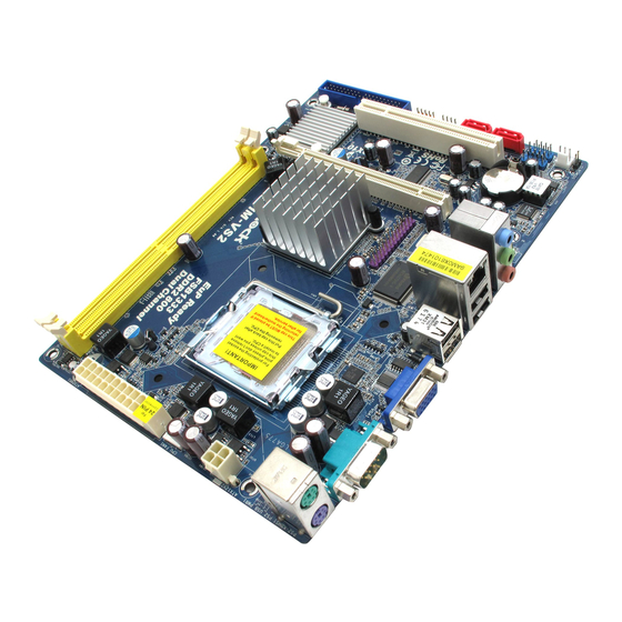
- Page 2 USB 2.0 Header (USB4_5, Blue) CPU Fan Connector (CPU_FAN1) Chassis Fan Connector (CHA_FAN1) ATX Power Connector (ATXPWR1) Clear CMOS Jumper (CLRCMOS1) 2 x 240-pin DDR2 DIMM Slots USB 2.0 Header (USB6_7, Blue) (Dual Channel: DDRII_1, DDRII_2; Yellow) PCI Slot (PCI1) North Bridge Controller...
- Page 3 COM Port Line Out (Lime) PS/2 Keyboard Port (Purple) * To enable Multi-Streaming function, you need to connect a front panel audio cable to the front panel audio header. Please refer to below steps for the software setting of Multi-Streaming. ®...
- Page 4 This Quick Installation Guide contains introduction of the motherboard and step-by- step installation guide. More detailed information of the motherboard can be found in the user manual presented in the Support CD. Because the motherboard specifications and the BIOS software might be updated, the content of this manual will be subject to change without notice.
- Page 5 Specifications Specifications Specifications Specifications Specifications Platform - Micro ATX Form Factor: 8.8-in x 6.7-in, 22.4 cm x 17.0 cm ® - LGA 775 for Intel Core 2 Extreme / Core 2 Quad / Core ® ® ® 2 Duo / Pentium...
- Page 6 Connector - 2 x SATAII 3.0 Gb/s connectors (No Support for RAID and “Hot Plug” functions) (see CAUTION 6) - 1 x ATA100 IDE connector (supports 2 x IDE devices) - 1 x Print port header - CPU/Chassis FAN connector...
- Page 7 Overclocking may affect your system stability, or even cause damage to the components and devices of your system. It should be done at your own risk and expense. We are not responsible for possible damage caused by overclocking.
- Page 8 USB flash drive or hard drive must use FAT32/16/12 file system. 11. The software name itself – OC DNA literally tells you what it is capable of. OC DNA, an exclusive utility developed by ASRock, provides a conve- nient way for the user to record the OC settings and share with others.
-
Page 9: Cpu Installation
Before you insert the 775-LAND CPU into the socket, please check if the CPU surface is unclean or if there is any bent pin on the socket. Do not force to insert the CPU into the socket if above situation is found. - Page 10 775-LAND CPU For proper inserting, please ensure to match the two orientation key notches of the CPU with the two alignment keys of the socket. Step 2-3. Carefully place the CPU into the socket by using a purely vertical motion.
- Page 11 1. It is recommended to use the cap tab to handle and avoid kicking off the PnP cap. 2. This cap must be placed if returning the motherboard for after service. Step 4. Close the socket: Step 4-1. Rotate the load plate onto the IHS.
- Page 12 Unlock a DIMM slot by pressing the retaining clips outward. Step 2. Align a DIMM on the slot such that the notch on the DIMM matches the break on the slot. The DIMM only fits in one correct orientation. It will cause permanent damage to the motherboard and the DIMM if you force the DIMM into the slot at incorrect orientation.
- Page 13 PCI slot: PCI slot is used to install expansion card that has the 32-bit PCI interface. PCIE slot: PCIE1 (PCIE x16 slot) is used for PCI Express card with x16 lane width graphics card. If you install the add-on PCI Express VGA card to PCIE1 (PCIE x16 slot), the onboard VGA will be disabled.
- Page 14 2-pin jumper (see p.2 No. 15) Note: CLRCMOS1 allows you to clear the data in CMOS. The data in CMOS includes system setup information such as system password, date, time, and system setup parameters. To clear and reset the system parameters to default setup, please turn off the computer and unplug the power cord from the power supply.
- Page 15 IDE devices to the motherboard 80-conductor ATA 66/100 cable Note: Please refer to the instruction of your IDE device vendor for the details. Serial ATAII Connectors These Serial ATAII (SATAII) connectors support SATAII (SATAII_1: see p.2, No. 12)
- Page 16 HDA to function correctly. Please follow the instruction in our manual and chassis manual to install your system. 2. If you use AC’97 audio panel, please install it to the front panel audio header as below: A.
- Page 17 Though this motherboard provides 4-Pin CPU fan (Quiet Fan) support, the 3-Pin CPU fan still can work successfully even without the fan speed control function. If you plan to connect the 3-Pin CPU fan to the CPU fan connector on this motherboard, please connect it to Pin 1-3.
- Page 18 Though this motherboard provides 24-pin ATX power connector, it can still work if you adopt a traditional 20-pin ATX power supply. To use the 20-pin ATX power supply, please plug your power supply along with Pin 1 and Pin 13.
-
Page 19: Driver Installation Guide
STEP 2: Connect the SATA power cable to the SATA / SATAII hard disk. STEP 3: Connect one end of the SATA data cable to the motherboard’s SATAII connector. STEP 4: Connect the other end of the SATA data cable to the SATA / SATAII hard disk. 2 . 8 2 . - Page 20 ROM drive. It will display the Main Menu automatically if “AUTORUN” is enabled in your computer. If the Main Menu does not appear automatically, locate and double- click on the file “ASSETUP.EXE” from the BIN folder in the Support CD to display the menus.
- Page 21 Wir danken Ihnen für den Kauf des ASRock G41M-VS2 Motherboard, ein zuverlässiges Produkt, welches unter den ständigen, strengen Qualitätskontrollen von ASRock gefertigt wurde. Es bietet Ihnen exzellente Leistung und robustes Design, gemäß der Verpflichtung von ASRock zu Qualität und Halbarkeit.
- Page 22 Spezifikationen Spezifikationen Spezifikationen Spezifikationen Spezifikationen Plattform - Micro ATX-Formfaktor: 22.4 cm x 17.0 cm; 8.8 Zoll x 6.7 Zoll ® - LGA 775 für Intel Core 2 Extreme / Core 2 Quad / Core 2 Duo / Pentium ® Dual Core / Celeron ®...
- Page 23 - 1 x RJ-45 LAN Port mit LED (ACT/LINK LED und SPEED LED) - Audioanschlüsse: Line In / Line Out / Mikrofon Anschlüsse - 2 x SATAII-Anschlüsse, unterstützt bis 3.0 Gb/s Datenübertragungsrate (Unterstützt keine “RAID”- und “Hot- Plug”-Funktionen) (siehe VORSICHT 6) - 1 x ATA100 IDE-Anschlüsse (Unterstützt bis 2 IDE-Geräte)
- Page 24 Beachten Sie bitte, dass Overclocking, einschließlich der Einstellung im BIOS, Anwenden der Untied Overclocking-Technologie oder Verwenden von Overclocking-Werkzeugen von Dritten, mit einem gewissen Risiko behaftet ist. Overclocking kann sich nachteilig auf die Stabilität Ihres Systems auswirken oder sogar Komponenten und Geräte Ihres Systems beschädigen.
- Page 25 USB-Flash-Laufwerk oder die Festplatte das Dateisystem FAT32/16/12 benutzen muss. 11. Allein der Name – OC DNA* – beschreibt es wörtlich, was die Software zu leisten vermag. OC DNA ist ein von ASRock exklusiv entwickeltes Dienstprogramm, das Nutzern eine bequeme Möglichkeit bietet, Übertaktungseinstellungen aufzuzeichnen und sie Anderen mitzuteilen.
- Page 26 Shutdown durch. Bevor Sie das System neu starten, prüfen Sie bitte, ob der CPU-Lüfter am Motherboard richtig funktioniert, und stecken Sie bitte den Stromkabelstecker aus und dann wieder ein. Um die Wärmeableitung zu verbessern, bitte nicht vergessen, etwas Wärmeleitpaste zwischen CPU und Kühlkörper zu sprühen.
- Page 27 +5VSB (Standby) zu setzen (siehe S.2 - No. 1) und die PS/2 oder USB- Weckfunktionen zu aktivieren. Hinweis: Um +5VSB nutzen zu können, muss das Netzteil auf dieser Leitung 2A oder mehr leisten können. CMOS löschen (CLRCMOS1, 2-Pin jumper) 2-Pin jumper (siehe S.2 - No.
- Page 28 Möchten Sie diese Energiesparfunktion deaktivieren, müssen Sie Pin 2 und Pin 3 schließen. Wird der EUP_LAN-Jumper auf aktiviert gesetzt, beachten Sie bitte, dass die Wake-On-LAN-Funktion bei S3 (Suspend-to-RAM), S4 (Suspend-to-Disk) und S5 (Standby) deaktiviert ist. (EuP deaktivieren) 1.4 Integrierte Header und Anschlüsse 1.4 Integrierte Header und Anschlüsse...
- Page 29 Geräte), wobei jedoch die Bildschirmverdrahtung am Gehäuse HDA unterstützen muss, um richtig zu funktionieren. Beachten Sie bei der Installation im System die Anweisungen in unserem Handbuch und im Gehäusehandbuch. 2. Wenn Sie die AC’97-Audioleiste verwenden, installieren Sie diese wie nachstehend beschrieben an der Front-Audioanschlussleiste: A.
- Page 30 F. Rufen Sie das Windows-System auf. Klicken Sie auf das Symbol in der Taskleiste unten rechts, um den Realtek HD Audio-Manager aufzurufen. ® Für Windows XP / XP 64-Bit Betriebssystem: Klicken Sie auf “Audio-E/A”, wählen Sie die “Anschlusseinstellungen” , wählen Sie “Erkennung der Frontleistenbuchse deaktivieren”...
- Page 31 (siehe S.2 - No. 4) Obwohl dieses Motherboard einen 24-pol. ATX-Stromanschluss bietet, kann es auch mit einem modifizierten traditionellen 20-pol. ATX-Netzteil verwendet werden. Um ein 20-pol. ATX-Netzteil zu verwenden, stecken Sie den Stecker mit Pin 1 und Pin 13 ein. Installation eines 20-pol. ATX-Netzteils Anschluss für...
- Page 32 Erscheint der Wilkommensbildschirm nicht, so “doppelklicken” Sie bitte auf das File ASSETUP.EXE im BIN-Verzeichnis der Support-CD, um die Menüs aufzurufen. Das Setup-Programm soll es Ihnen so leicht wie möglich machen. Es ist menügesteuert, d.h. Sie können in den verschiedenen Untermenüs Ihre Auswahl treffen und die Programme werden dann automatisch installiert.
- Page 33 1.1 Contenu du paquet Carte mère ASRock G41M-VS2 (Facteur de forme Micro ATX: 8.8 pouces x 6.7 pouces, 22.4 cm x 17.0 cm) Guide d’installation rapide ASRock G41M-VS2 CD de soutien ASRock G41M-VS2 Un câble ruban IDE Ultra ATA 66/100 80 conducteurs (en option) Un câble de données Serial ATA (SATA) (en option)
- Page 34 - Prise en charge de la technologie Hyper-Threading (voir ATTENTION 1) - Prend en charge la technologie Untied Overclocking (voir ATTENTION 2) - Prise en charge de la technologie EM64T par le CPU ® Chipsets - Northbridge: Intel - Southbridge: Intel ®...
- Page 35 - 1 x port LAN RJ-45 avec LED (ACT/LED CLIGNOTANTE et LED VITESSE) - Jack audio: entrée ligne / sortie ligne / microphone Connecteurs - 2 x connecteurs SATAII, prennent en charge un taux de transfert de données pouvant aller jusqu’à 3.0Go/s (Ne supporte pas les fonctions “RAID”...
- Page 36 - FCC, CE - Prêt pour EuP (alimentation Prêt pour EuP requise) (voir ATTENTION 14) * Pour de plus amples informations sur les produits, s’il vous plaît visitez notre site web: http://www.asrock.com ATTENTION Il est important que vous réalisiez qu’il y a un certain risque à effectuer l’overclocking, y compris ajuster les réglages du BIOS, appliquer la technologie Untied Overclocking, ou...
- Page 37 Pour améliorer la dissipation de la chaleur, n’oubliez pas de mettre de la pâte thermique entre le CPU le dissipateur lors de l’installation du PC.
- Page 38 électrique dont l’efficacité électrique 5Vsb est supérieure à 50% pour une consommation de courant de 100 mA, votre système sera conforme à la norme EuP. Le réglage par défaut (codes pin1 et pin2) est activé pour être conforme à EuP. Si vous souhaitez désactiver cette fonction de sauvegarde de l’énergie, vous pouvez changez les codes pin2 et pin3.
- Page 39 LAN sous S3 (Suspendre vers RAM), S4 (Suspendre vers Disque), et S5 (Arrêt doux) sera désactivée. (Désactiver EuP) 1.4 En-têtes et Connecteurs sur Carte 1.4 En-têtes et Connecteurs sur Carte 1.4 En-têtes et Connecteurs sur Carte 1.4 En-têtes et Connecteurs sur Carte 1.4 En-têtes et Connecteurs sur Carte...
- Page 40 1. L’audio à haute définition (HDA) prend en charge la détection de fiche, mais le fil de panneau sur le châssis doit prendre en charge le HDA pour fonctionner correctement. Veuillez suivre les instructions dans notre manuel et le manuel de châssis afin installer votre système.
- Page 41 F. Entrer dans le système Windows. Cliquer sur l’icône sur la barre de tâches dans le coin inférieur droite pour entrer dans le Gestionnaire audio Realtek HD. ® Pour Windows XP / XP 64-bit OS: Cliquer sur « E/S audio», sélectionner « Paramètres du connecteur »...
- Page 42 1 2 3 4 ien que cette carte mère offre un support de (Ventilateur silencieux) ventilateur de CPU à 4 broches , le ventilateur de CPU à 3 broches peut bien fonctionner même sans la fonction de commande de vitesse du ventilateur.
- Page 43 BIOS après le POST, veuillez redémarrer le système en pressant <Ctl> + <Alt> + <Suppr>, ou en pressant le bouton de reset sur le boîtier du système. Vous pouvez également redémarrer en éteignant le système et en le rallumant.
- Page 44 Grazie per aver scelto una scheda madre ASRock G41M-VS2, una scheda madre affidabile prodotta secondo i severi criteri di qualità ASRock. Le prestazioni eccellenti e il design robusto si conformano all’impegno di ASRock nella ricerca della qualità e della resistenza.
- Page 45 1.2 Specifiche Specifiche Specifiche Specifiche Specifiche Piattaforma - Micro ATX Form Factor: 8.8-in x 6.7-in, 22.4 cm x 17.0 cm Processore - LGA 775 per Intel ® Core 2 Extreme / Core 2 Quad / Core ® ® ® Duo / Pentium...
- Page 46 Connettori - 2 x connettori SATAII 3.0Go/s (Non supporta le funzioni “RAID” e “Collegamento a caldo”) (vedi ATTENZIONE 6) - 1 x connettori ATA100 IDE (supporta fino a 2 dispositivi IDE) - 1 x Collettore porta stampante - Connettore ventolina CPU/telaio...
- Page 47 AVVISO Si prega di prendere atto che la procedura di overclocking implica dei rischi, come anche la regolazione delle impostazioni del BIOS, l’applicazione della tecnologia Untied Overclocking Technology, oppure l’uso di strumenti di overclocking forniti da terzi. L’overclocking può influenzare la stabilità del sistema, ed anche provocare danni ai componenti ed alle periferiche del sistema.
- Page 48 (dischi floppy) o altre complicate utilità Flash. Si prega di notare che l’unità Flash USB o il disco rigido devono usare il File System FAT32/16/ 11. Il nome stesso del software – OC DNA – dice di cosa è capace. OC DNA, una utilità esclusiva sviluppata da ASRock, fornisce un modo comodo per registrare le impostazioni OC e condividerle con gli altri.
- Page 49 Nota: CLRCMOS1 consente di pulire i dati nella CMOS. I dati nella CMOS includono informazioni del setup del sistema, come per esempio la password di sistema, la data, l’ora, e i parametri del setup di sistema. Per pulire I parametri di sistema e resettare ai parametri di default, spegnere il computer e scollegare l’alimentatore, poi collegare il jumper sul CLRCMOS1 per 5 secondi.
- Page 50 1.4 Collettori e Connettori su Scheda 1.4 Collettori e Connettori su Scheda I collettori ed i connettori su scheda NON sono dei jumper. NON installare cappucci per jumper su questi collettori e connettori. L’installazione di cappucci per jumper su questi collettori e connettori provocherà...
- Page 51 1. La caratteristica HDA (High Definition Audio) supporta il rilevamento dei connettori, però il pannello dei cavi sul telaio deve supportare la funzione HDA (High Definition Audio) per far sì che questa operi in modo corretto. Attenersi alle istruzioni del nostro manuale e del manuale del telaio per installare il sistema.
- Page 52 ® Vista / Vista 64-bit: Andare alla scheda “Microfono anteriore” nel pannello di controllo d i Realtek. Fare clic su “Imposta dispositivo predefinito” per impostare il microfono anteriore come dispositivo predefinito per la registrazione. Collettore pannello di sistema Questo collettore accomoda...
- Page 53 Sebbene la presente scheda madre disponga di un supporto per ventola CPU a 4 piedini (ventola silenziosa), la ventola CPU a 3 piedini è in grado di funzionare anche senza la funzione di controllo della velocità della ventola. Se si intende collegare la ventola CPU a 3 piedini al connettore della ventola CPU su questa scheda madre, collegarla ai piedini 1-3.
- Page 54 BIOS; altrimenti, POST continua con i suoi test di routine. Per entrare il BIOS Setup dopo il POST, riavvia il sistema premendo <Ctl> + <Alt> + <Delete>, o premi il tasto di reset sullo chassis del sistema. Per informazioni più dettagliate circa il Setup del BIOS, fare riferimento al Manuale dell’Utente (PDF file) contenuto nel cd di...
- Page 55 ASRock. Esta Guía rápida de instalación contiene una introducción a la placa base y una guía de instalación paso a paso. Puede encontrar una información más detallada sobre la placa base en el manual de usuario incluido en el CD de soporte.
- Page 56 1 . 2 1 . 2 Especificación Especificación Especificación Especificación Especificación Plataforma - Factor forma Micro ATX: 22,4 cm x 17,0 cm, 8,8” x 6,7” ® Procesador - LGA 775 para Intel Core 2 Extreme / Core 2 Quad / Core ®...
- Page 57 - 24-pin cabezal de alimentación ATX - 4-pin conector de ATX 12V power - Conector de audio de panel frontal - 2 x Conector USB 2.0 (compatible con 4 puertos USB 2.0) (vea ATENCIÓN 7) BIOS - 8Mb AMI BIOS - AMI legal BIOS - Soporta “Plug and Play”...
- Page 58 ADVERTENCIA Tenga en cuenta que hay un cierto riesgo implícito en las operaciones de aumento de la velocidad del reloj, incluido el ajuste del BIOS, aplicando la tecnología de aumento de velocidad liberada o utilizando las herramientas de aumento de velocidad de otros fabricantes.
- Page 59 ASRock Instant Flash. Ejecute esta herramienta y guarde el archivo correspondiente al sistema BIOS nuevo en su unidad flash USB, unidad de disco flexible o disco duro para poder actualizar el BIOS con sólo pulsar un par de botones, sin necesidad de preparar un disco flexible adicional ni utilizar complicadas utilidades de programación.
- Page 60 Unión Europea para establecer el consumo total de energía de un sistema. Según la disposición EuP, la alimentación de CA total para el sistema completo ha de ser inferior a 1,00W en modo apagado. Para cumplir con el estándar EuP, se requieren una placa base y una fuente de alimentación que cumplan con...
- Page 61 3 para habilitar +5VSB (vea p.2, N. 1) (standby) para PS/2 o USB wake up events. Atención: Para elegir +5VSB, se necesita corriente mas que 2 Amp proveida por la fuente de electricidad. Limpiar CMOS (CLRCMOS1, jumper de 2 pins) jumper de 2 pins (vea p.2, N.
- Page 62 1.4 Cabezales y Conectores en Placas 1.4 Cabezales y Conectores en Placas Los conectores y cabezales en placa NO son puentes. NO coloque las cubiertas de los puentes sobre estos cabezales y conectores. El colocar cubiertas de puentes sobre los conectores y cabezales provocará...
- Page 63 2. Si utiliza el panel de sonido AC’97, instálelo en la cabecera de sonido del panel frontal de la siguiente manera: A. Conecte Mic_IN (MIC) a MIC2_L.
- Page 64 F. Entre en el sistema Windows. Haga clic en el icono de la barra de tareas situada en la parte inferior derecha para entrar en el Administrador de audio HD Realtek. Para Windows ® XP / XP 64-bit OS: Haga clic en “E/S de audio”, seleccione “Configuración de conectores”...
- Page 65 (24-pin ATXPWR1) (vea p.2, N. 4) A pesar de que esta placa base incluye in conector de alimentación ATX de 24 pins, ésta puede funcionar incluso si utiliza una fuente de alimentación ATX de 20 pins tradicional. Para usar una fuente de alimentación ATX de 20 pins, por favor, conecte su fuente de alimentación usando los Pins 1 y 13.
- Page 66 Para iniciar la instalación, ponga el CD en el lector de CD y se desplegará el Menú Principal automáticamente si «AUTORUN» está habilitado en su computadora.
- Page 67 Gratos por comprar nossa placa–mãe G41M-VS2, um produto confiável feito com ASRock um estrito controle de qualidade consistente. Com um excelente desempenho, essa placa é dotada de um projeto robusto que atende a ASRock de compromisso com a qualidade e durabilidade.
- Page 68 1.2 Especificações 1.2 Especificações 1.2 Especificações 1.2 Especificações 1.2 Especificações Plataforma - Formato Micro ATX: 8,8 pol. x 6,7 pol., 22,4 cm x 17,0 cm ® - Socket Intel Dual Core Core 2 Extreme / Core 2 Quad / ®...
- Page 69 - Medição de temperatura da placa-mãe - Tacômetros de ventilador do Processador - Tacômetros de ventilador do chassis - Ventoinha silenciosa para a CPU - Monitoramento de voltagem : +12 V, +5 V, +3.3 V, Vcore ® ® Sistema - Microsoft...
- Page 70 AVISO Tenha em atenção que a operação de overclocking envolve alguns riscos, nomeadamente no que diz respeito ao ajuste das definições do BIOS, à aplicação da tecnologia Untied Overclocking ou à utilização de ferramentas de overclocking de terceiros. O overclocking pode afectar a estabilidade do seu sistema ou até...
- Page 71 10. ASRock Instant Flash est un utilitaire de flash du BIOS flash intégré dans la ROM Flash. Cet outil pratique de mise à jour du BIOS vous permet de mettre à jour le BIOS du système sans entrer d’abord dans un système d’exploitation tel que MS-DOS ou Windows...
- Page 72 (veja a folha 2, No. 1) para PS/2 ou eventos de wake up na USB. Nota: Para escolher +5VSB, é preciso uma corrente de stand by de 2 A ou mais. Restaurar CMOS (CLRCMOS1, jumper de 2 pinos) jumper de 2 pinos (veja a folha 2, No.
- Page 73 1.4 Conectores 1.4 Conectores 1.4 Conectores 1.4 Conectores 1.4 Conectores Os conectores NÃO SÃO jumpers. NÃO coloque capas de jumper sobre estes conectores. A colocação de pontos de jumper sobre os conectores causará danos irreversíveis à placa-mãe. Conector Figura Descrição Conector primário (Azul)
- Page 74 Siga s instruções que aparecem no manual e no manual do chassis para instalar o sistema. 2. Se utilizar o painel de áudio AC’97, instale-o no cabeçalho de áudio do painel frontal, como a figura abaixo mostra: A. Ligue o Mic_IN (MIC) ao MIC2_L.
- Page 75 XP / XP 64-bit OS: Queira seleccionar “Front Mic” (Microfone Frontal) como dispositivo de gravação predefinido. Se quer ouvir a sua voz através do microfone frontal, queira desmarcar o ícone “Mute” (Sem som) em “Front Mic” (Microfone Frontal) da parte “Playback” (Reprodução).
- Page 76 20 pinos. Para usar a fonte de alimentação de 29 pinos, por favor ligue a sua fonte de alimentação com o Pino 1 e o Pino 13. Instalação da Fonte de alimentação ATX de 20 Pinos Conector ATX 12 V Note que é...
- Page 77 Se desejar acessar o Utilitário de Configuração do BIOS depois do POST, reinicie o sistema pressionando <Ctl> + <Alt> + <Del>, ou pressionando o botão de reinício no chassi do sistema. Para as informações detalhadas sobre o Utilitário de Configuração do BIOS, consulte o Manual do Usuário (arquivo PDF) no CD de suporte.
- Page 78 ASRock G41M-VS2 Motherboard...
- Page 79 ® ® ® ® ® ® ® ® ® ASRock G41M-VS2 Motherboard...
- Page 80 ® ASRock G41M-VS2 Motherboard...
- Page 81 “ ” ® ® ® ® ® “ ” “ ” ® ASRock G41M-VS2 Motherboard...
- Page 82 ® ASRock G41M-VS2 Motherboard...
- Page 83 “ ” “ ” “ ” “ ” ASRock G41M-VS2 Motherboard...
- Page 84 SATAII_1 SATAII_2 ASRock G41M-VS2 Motherboard...
- Page 85 ® ASRock G41M-VS2 Motherboard...
- Page 86 ® ® ® “ ” “ ” “ ” “ ” ® “ ” “ ” 1 2 3 4 ASRock G41M-VS2 Motherboard...
- Page 87 ASRock G41M-VS2 Motherboard...
- Page 88 “ ” “ ” ASRock G41M-VS2 Motherboard...
- Page 89 1 0 0 1 0 0 1 0 0 1 0 0 1 0 0 ASRock G41M-VS2 Motherboard...
- Page 90 ® ® ® ® ® ® ® ® ® 1 0 1 1 0 1 1 0 1 1 0 1 1 0 1 ASRock G41M-VS2 Motherboard...
- Page 91 ® ® 1 0 2 1 0 2 1 0 2 1 0 2 1 0 2 ASRock G41M-VS2 Motherboard...
- Page 92 ® ® ® ® ® ® ® ® 1 0 3 1 0 3 1 0 3 1 0 3 1 0 3 ASRock G41M-VS2 Motherboard...
- Page 93 ® 1 0 4 1 0 4 1 0 4 1 0 4 1 0 4 ASRock G41M-VS2 Motherboard...
- Page 94 1 0 5 1 0 5 1 0 5 1 0 5 1 0 5 ASRock G41M-VS2 Motherboard...
- Page 95 SATAII_1 SATAII_2 1 0 6 1 0 6 1 0 6 1 0 6 1 0 6 ASRock G41M-VS2 Motherboard...
- Page 96 ® ® ® 1 0 7 1 0 7 1 0 7 1 0 7 1 0 7 ASRock G41M-VS2 Motherboard...
- Page 97 ® 1 2 3 4 1 0 8 1 0 8 1 0 8 1 0 8 1 0 8 ASRock G41M-VS2 Motherboard...
- Page 98 ® ® 1 0 9 1 0 9 1 0 9 1 0 9 1 0 9 ASRock G41M-VS2 Motherboard...
- Page 99 1 1 0 1 1 0 1 1 0 1 1 0 1 1 0 ASRock G41M-VS2 Motherboard...
- Page 100 1 1 1 1 1 1 1 1 1 1 1 1 1 1 1 ASRock G41M-VS2 Motherboard...
- Page 101 ® ® ® ® ® ® ® ® ® 1 1 2 1 1 2 1 1 2 1 1 2 1 1 2 ASRock G41M-VS2 Motherboard...
- Page 102 ® ® 1 1 3 1 1 3 1 1 3 1 1 3 1 1 3 ASRock G41M-VS2 Motherboard...
- Page 103 ® ® ® ® ® ® ® ® 1 1 4 1 1 4 1 1 4 1 1 4 1 1 4 ASRock G41M-VS2 Motherboard...
- Page 104 ® 1 1 5 1 1 5 1 1 5 1 1 5 1 1 5 ASRock G41M-VS2 Motherboard...
- Page 105 1 1 6 1 1 6 1 1 6 1 1 6 1 1 6 ASRock G41M-VS2 Motherboard...
- Page 106 1 1 7 1 1 7 1 1 7 1 1 7 1 1 7 ASRock G41M-VS2 Motherboard...
- Page 107 ® ® ® ® 1 1 8 1 1 8 1 1 8 1 1 8 1 1 8 ASRock G41M-VS2 Motherboard...
- Page 108 ® 1 2 3 4 1 1 9 1 1 9 1 1 9 1 1 9 1 1 9 ASRock G41M-VS2 Motherboard...
- Page 109 ® ® ® 1 2 0 1 2 0 1 2 0 1 2 0 1 2 0 ASRock G41M-VS2 Motherboard...
Need help?
Do you have a question about the G41M-VS2 and is the answer not in the manual?
Questions and answers