HP t200 Zero Maintenance And Service Manual
Client for multiseat
Hide thumbs
Also See for t200 Zero:
- User manual (47 pages) ,
- Quick setup manual (16 pages) ,
- Manual (16 pages)

Subscribe to Our Youtube Channel
Related Manuals for HP t200 Zero


Summary of Contents for HP t200 Zero
- Page 1 Maintenance and Service Guide HP MultiSeat ms6200 and HP t200 Zero Client For MultiSeat...
- Page 2 No part of this document may be photocopied, reproduced, or translated to another language without the prior written consent of Hewlett-Packard Company. HP Business PC Maintenance and Guide HP MultiSeat ms6200 and HP t200 Zero Client For MultiSeat First Edition (October 2011) Document Part Number: 675835-001...
-
Page 3: About This Book
About This Book WARNING! Text set off in this manner indicates that failure to follow directions could result in bodily harm or loss of life. CAUTION: Text set off in this manner indicates that failure to follow directions could result in damage to equipment or loss of information. - Page 4 About This Book...
-
Page 5: Table Of Contents
Front Panel Components ..................... 2 Media Card Reader Components ..................3 Rear Panel Components ..................... 4 Serial Number Location ....................... 4 HP t200 Zero Client ..........................5 Front Panel Components ..................... 5 Rear Panel Components ..................... 6 Serial Number Location ....................... 6 2 HP MultiSeat Computing Solution –... - Page 6 Licensing and Support ........................14 External Links ............................. 14 Troubleshooting ..........................14 LED Codes ............................15 3 Computer Setup (F10) Utility ........................16 Computer Setup (F10) Utilities ......................16 Using Computer Setup (F10) Utilities ................17 Computer Setup—File ....................... 18 Computer Setup—Storage ....................
- Page 7 5 Removal and Replacement Procedures ..................... 38 Preparation for Disassembly ......................38 Access Panel ............................39 Front Bezel ............................40 Bezel Blanks ............................41 Memory .............................. 41 DIMMs ..........................41 DDR3-SDRAM DIMMs ...................... 41 Populating DIMM Sockets ....................42 Installing DIMMs ........................ 43 Expansion Card ..........................
- Page 8 Resetting the Password Jumper ...................... 101 Clearing and Resetting the CMOS ....................102 Appendix E Drive Protection System (DPS) ....................104 Accessing DPS Through Computer Setup ..................105 Appendix F Specifications ..........................106 ms6200 ............................. 106 t200 Specifications ........................... 107 Index ................................. 108 viii...
-
Page 9: Product Features
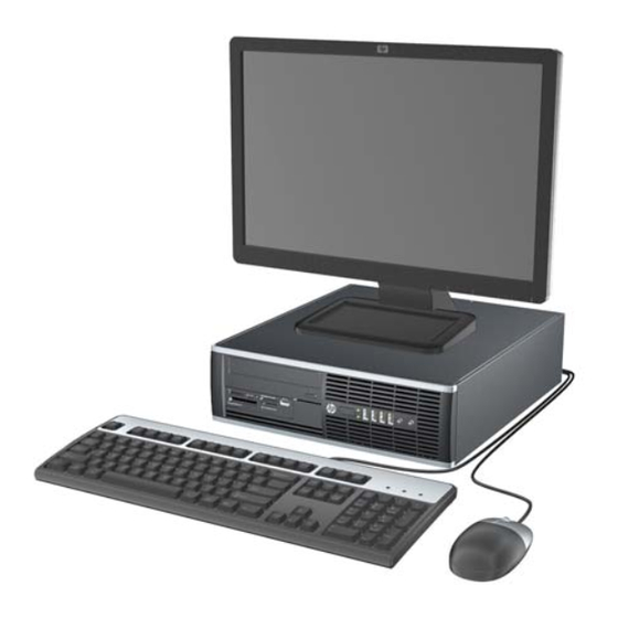
Product Features HP MultiSeat ms6200 Standard Configuration Features Features may vary depending on the model. For a complete listing of the hardware and software installed in the computer, run the diagnostic utility (included on some computer models only). Figure 1-1 Small Form Factor Configuration NOTE: The MultiSeat computer can also be used in a tower orientation. -
Page 10: Front Panel Components
Front Panel Components Drive configuration may vary by model. Some models have a bezel blank covering one or more drive bays. Figure 1-2 Front Panel Components Table 1-1 Front Panel Components 5.25-inch Optical Drive Microphone/Headphone Connector Dual-State Power Button 3.5-inch Media Card Reader (optional) Power On Light Hard Drive Activity Light USB (Universal Serial Bus) Ports... -
Page 11: Media Card Reader Components
Media Card Reader Components The media card reader is an optional device available on some models only. Refer to the following illustration and table to identify the media card reader components. Figure 1-3 Media Card Reader Components Table 1-2 Media Card Reader Components Slot Media ●... -
Page 12: Rear Panel Components
Rear Panel Components Figure 1-4 Rear Panel Components RJ-45 Network Connector DisplayPort Monitor Connector Serial Connector VGA Monitor Connector PS/2 Mouse Connector (green) PS/2 Keyboard Connector (purple) Power Cord Connector Line-Out Connector for powered audio devices (green) Universal Serial Bus (USB) ports Line-In Audio Connector (blue) Serial Number Location Each computer has a unique serial number and a product ID number that are located on the top... -
Page 13: Hp T200 Zero Client
HP t200 Zero Client Front Panel Components For more information, http://www.hp.com and search for your specific t200 Zero Client model to find the model-specific QuickSpecs. Figure 1-6 Front panel components Power LED Line-out (headphone) audio connector Line-in (microphone) connector USB 2.0 connectors (4) -
Page 14: Rear Panel Components
Serial Number Location Figure 1-8 Serial number location Every t200 Zero Client includes a unique serial number located as shown in the following illustration. Have this number available when contacting HP customer service for assistance. Chapter 1 Product Features... -
Page 15: Hp Multiseat Computing Solution - Best Practices
HP MultiSeat Computing Solution – Best Practices ® ® Offerings of Microsoft Windows MultiPoint™ Server 2011 OEM Standard ● HP MultiSeat ms6200 Desktop (the host PC) ships preinstalled from the factory with Windows MultiPoint Server 2011, which includes the server Certificate of Authenticity (COA) and the host station Client Access License (CAL) ●... -
Page 16: Academic Volume License
Academic Volume License ● HP MultiSeat ms6200 Desktop sold with FreeDOS installed and no Client Access License (CAL) provided ● Requires the purchase of the Academic Volume License version of MultiPoint Server 2011 ● Device drivers must be downloaded from HP and installed ●... -
Page 17: Topology
NOTE: The maximum cable length supported by USB 2.0 specification is five meters. You cannot mix t100 or t150 clients with t200 Zero Clients connected to the same MultiSeat host PC, but you can mix t100 and t150 client devices. -
Page 18: Topology Examples
Windows MultiPoint Server 2011 now provides private USB functionality on client stations. For example, a USB flash drive connected to a USB port on a t150 client or a t200 Zero Client will be accessible only to the user on that station. A USB flash drive connected to the host PC, however, will be accessible to all users. -
Page 19: Best Practices For Setting Up A Multiseat Environment
If the t200 Zero Client drivers are not preinstalled on your host PC, please download them from the HP website. Go to hp.com, click SUPPORT & DRIVERS, click Drivers & Software, type the host PC model number (ms6200) in the field, and click SEARCH to find the latest t200 Zero Client drivers. - Page 20 Each host in the subnet must have a unique hotkey. Ensure that the t200 Zero Client is not already assigned to a host by confirming that the LED blinks alternately blue and amber. Refer to the reset methods above, if needed.
-
Page 21: Best Practices For Installation Of Drivers With The Volume License Operating System
Best Practices for Installation of Drivers with the Volume License Operating System Recommended Method (Automatic Driver Installation) Before installing the Windows MultiPoint Server 2011 Volume License operating system from DVD, go to www.hp.com and search for drivers for your host PC model. Choose the MultiPoint 2011 OS then locate and download the "HP Install Assistant"... -
Page 22: Performance Considerations
Cause Solution The MultiSeat zero client has a lower maximum resolution The maximum resolution supported by the t200 Zero Client is than some larger monitors can display. 2048 x 1152. Chapter 2 HP MultiSeat Computing Solution – Best Practices... -
Page 23: Led Codes
The MP2011 Auto-Login feature cannot work if the user Set a password on the user account. account used does not have a password. LED Codes Table 2-1 USB-connected HP t200 Zero Client for MultiSeat Solid amber USB-powered Solid blue DC-powered Table 2-2 Ethernet–connected HP t200 Zero Client for MultiSeat... -
Page 24: Computer Setup (F10) Utility
Computer Setup (F10) Utility Computer Setup (F10) Utilities Use Computer Setup (F10) Utility to do the following: ● Change factory default settings. ● Set the system date and time. ● Set, view, change, or verify the system configuration, including settings for processor, graphics, memory, audio, storage, communications, and input devices. -
Page 25: Using Computer Setup (F10) Utilities
● Solve system configuration errors detected but not automatically fixed during the Power-On Self- Test (POST). ● Replicate the system setup by saving system configuration information on a USB device and restoring it on one or more computers. ● Execute self-tests on a specified ATA hard drive (when supported by drive). ●... -
Page 26: Computer Setup-File
Computer Setup—File NOTE: Support for specific Computer Setup options may vary depending on the hardware configuration. Table 3-2 Computer Setup—File Option Description System Information Lists: ● Product name ● SKU number (some models) ● Processor type/speed/stepping ● Cache size (L1/L2/L3) (dual core processors have this listed twice) ●... -
Page 27: Computer Setup-Storage
Computer Setup—Storage NOTE: Support for specific Computer Setup options may vary depending on the hardware configuration. Table 3-3 Computer Setup—Storage Option Description Device Configuration Lists all installed BIOS-controlled storage devices. When a device is selected, detailed information and options are displayed. The following options may be presented: CD-ROM: Size, model, firmware version, serial number, connector color (not included for USB CD-ROM). - Page 28 Table 3-3 Computer Setup—Storage (continued) Storage Options eSATA Port (some models) Allows you to set a SATA port as an eSATA port for use with an external drive. Default is enabled. This setting affects only the port with the black connector, labeled as eSATA on the system board. This port should have the eSATA back panel connector attached to use eSATA drives.
-
Page 29: Computer Setup-Security
Table 3-3 Computer Setup—Storage (continued) DPS Self-Test Allows you to execute self-tests on ATA hard drives capable of performing the Drive Protection System (DPS) self-tests. NOTE: This selection will only appear when at least one drive capable of performing the DPS self-tests is attached to the system. - Page 30 Table 3-4 Computer Setup—Security (continued) Power-On Password Allows you to set and enable a power-on password. The power-on password prompt appears after a power cycle. If the user does not enter the correct power-on password, the unit will not boot. NOTE: This selection will only appear when at least one drive that supports the DriveLock feature is attached to the system.
- Page 31 Table 3-4 Computer Setup—Security (continued) USB Security Allows you to set Enabled/Disabled (default is Enabled) for: ● Front USB Ports ◦ USB Port 1 ◦ USB Port 2 ◦ USB Port 3 ◦ USB Port 4 ● Rear USB Ports ◦...
- Page 32 Table 3-4 Computer Setup—Security (continued) System Security Data Execution Prevention (enable/disable) - Helps prevent operating system security breaches. (some models: these Default is enabled. options are hardware Virtualization Technology (VTx)(some models) (enable/disable) - Controls the virtualization dependent) features of the processor. Changing this setting requires turning the computer off and then back on.
-
Page 33: Computer Setup-Power
Computer Setup—Power NOTE: Support for specific Computer Setup options may vary depending on the hardware configuration. Table 3-5 Computer Setup—Power Option Description ● OS Power Runtime Power Management— Enable/Disable. Allows certain operating systems to reduce Management processor voltage and frequency when the current software load does not require the full capabilities of the processor. -
Page 34: Computer Setup-Advanced
Computer Setup—Advanced NOTE: Support for specific Computer Setup options may vary depending on the hardware configuration. Table 3-6 Computer Setup—Advanced (for advanced users) Option Heading Power-On Options Allows you to set: ● POST mode (QuickBoot, Clear Memory, FullBoot, or FullBoot Every x Days). ◦... - Page 35 Table 3-6 Computer Setup—Advanced (for advanced users) (continued) Bus Options On some models, allows you to enable or disable: ● PCI SERR# Generation. Default is enabled. ● PCI VGA Palette Snooping, which sets the VGA palette snooping bit in PCI configuration space;...
-
Page 36: Recovering The Configuration Settings
Recovering the Configuration Settings This method of recovery requires that you first perform the Save to Removable Media command with the Computer Setup (F10) Utility before Restore is needed. (See Save to Removable Media on page 18 in the Computer Setup—File table.) NOTE: It is recommended that you save any modified computer configuration settings to a USB flash media device and save the device for possible future use. -
Page 37: Routine Care, Sata Drive Guidelines, And Disassembly Preparation
Routine Care, SATA Drive Guidelines, and Disassembly Preparation This chapter provides general service information for the computer. Adherence to the procedures and precautions described in this chapter is essential for proper service. CAUTION: When the computer is plugged into an AC power source, voltage is always applied to the system board. -
Page 38: Preventing Electrostatic Damage To Equipment
Removing DIPs from vinyl tray 2,000 V 4,000 V 11,500 V Removing DIPs from Styrofoam 3,500 V 5,000 V 14,500 V Removing bubble pack from PCB 7,000 V 20,000 V 26,500 V Packing PCBs in foam-lined box 5,000 V 11,000 V 21,000 V These are then multi-packaged inside plastic tubes, trays, or Styrofoam. -
Page 39: Grounding The Work Area
Grounding the Work Area To prevent static damage at the work area, use the following precautions: ● Cover the work surface with approved static-dissipative material. Provide a wrist strap connected to the work surface and properly grounded tools and equipment. ●... -
Page 40: Operating Guidelines
Operating Guidelines To prevent overheating and to help prolong the life of the computer: ● Keep the computer away from excessive moisture, direct sunlight, and extremes of heat and cold. ● Operate the computer on a sturdy, level surface. Leave a 10.2-cm (4-inch) clearance on all vented sides of the computer and above the monitor to permit the required airflow. -
Page 41: Cleaning The Keyboard
To clean the computer case, follow the procedures described below: ● To remove light stains or dirt, use plain water with a clean, lint-free cloth or swab. ● For stronger stains, use a mild dishwashing liquid diluted with water. Rinse well by wiping it with a cloth or swab dampened with clear water. -
Page 42: Cleaning The Mouse
Cleaning the Mouse Before cleaning the mouse, ensure that the power to the computer is turned off. ● Clean the mouse ball by first removing the retaining plate and the ball from the housing. Pull out any debris from the ball socket and wipe the ball with a clean, dry cloth before reassembly. ●... -
Page 43: Cables And Connectors
Cables and Connectors Most cables used throughout the unit are flat, flexible cables. These cables must be handled with care to avoid damage. Apply only the tension required to seat or unseat the cables during insertion or removal from the connector. Handle cables by the connector whenever possible. In all cases, avoid bending or twisting the cables, and ensure that the cables are routed in such a way that they cannot be caught or snagged by parts being removed or replaced. -
Page 44: Sata Hard Drives
SATA Hard Drives Serial ATA Hard Drive Characteristics Number of pins/conductors in data cable Number of pins in power cable Maximum data cable length 39.37 in (100 cm) Data interface voltage differential 400-700 mV Drive voltages 3.3 V, 5 V, 12 V Jumpers for configuring drive Data transfer rate 3.0 Gb/s... - Page 45 ● Some flat ribbon cables come prefolded. Never change the folds on these cables. ● Do not bend any cable sharply. A sharp bend can break the internal wires. ● Never bend a SATA data cable tighter than a 30 mm (1.18 in) radius. ●...
-
Page 46: Removal And Replacement Procedures
Removal and Replacement Procedures Adherence to the procedures and precautions described in this chapter is essential for proper service. After completing all necessary removal and replacement procedures, run the Diagnostics utility to verify that all components operate properly. NOTE: Not all features listed in this guide are available on all computers. Preparation for Disassembly Routine Care, SATA Drive Guidelines, and Disassembly Preparation on page 29 for initial safety... -
Page 47: Access Panel
Access Panel Prepare the computer for disassembly (Preparation for Disassembly on page 38). If the computer is on a stand, remove the computer from the stand. Lift up on the access panel handle (1) then lift the access panel off the computer (2). Figure 5-1 Removing the access panel To install the access panel, reverse the removal procedure. -
Page 48: Front Bezel
Front Bezel Prepare the computer for disassembly (Preparation for Disassembly on page 38). Remove the access panel (Access Panel on page 39). Lift up the three tabs on the side of the bezel (1), then rotate the bezel off the chassis (2). Figure 5-2 Removing the front bezel To install the front bezel, reverse the removal procedure. -
Page 49: Bezel Blanks
Bezel Blanks On some models, there are bezel blanks covering the 3.5-inch and 5.25-inch external drive bays that need to be removed before installing a drive. To remove a bezel blank: Remove the access panel (Access Panel on page 39). Remove the front bezel (Front Bezel on page 40).. -
Page 50: Populating Dimm Sockets
For proper system operation, the DDR3-SDRAM DIMMs must be: ● industry-standard 240-pin ● unbuffered non-ECC PC3-8500 DDR3-1066 MHz-compliant or PC3-10600 DDR3-1333 MHz- compliant ● 1.5 volt DDR3-SDRAM DIMMs The DDR3-SDRAM DIMMs must also: ● support CAS latency 7 DDR3 1066 MHz (7-7-7 timing) and CAS latency 9 DDR3 1333 MHz (9-9-9 timing) ●... -
Page 51: Installing Dimms
Installing DIMMs CAUTION: You must disconnect the power cord and wait approximately 30 seconds for the power to drain before adding or removing memory modules. Regardless of the power-on state, voltage is always supplied to the memory modules as long as the computer is plugged into an active AC outlet. Adding or removing memory modules while voltage is present may cause irreparable damage to the memory modules or system board. -
Page 52: Expansion Card
Push the module down into the socket, ensuring that the module is fully inserted and properly seated. Make sure the latches are in the closed position (3). Repeat steps 4 and 5 to install any additional modules. Replace the access panel. If the computer was on a stand, replace the stand. - Page 53 Before installing an expansion card, remove the expansion slot cover or the existing expansion card. NOTE: Before removing an installed expansion card, disconnect any cables that may be attached to the expansion card. If you are installing an expansion card in a vacant socket, remove the appropriate expansion slot cover on the back of the chassis.
- Page 54 If you are removing a PCI Express x16 card, pull the retention arm on the back of the expansion socket away from the card and carefully rock the card back and forth until the connectors pull free from the socket. Pull the expansion card straight up from the socket then away from the inside of the chassis to release it from the chassis frame.
- Page 55 To install a new expansion card, hold the card just above the expansion socket on the system board then move the card toward the rear of the chassis (1) so that the bracket on the card is aligned with the open slot on the rear of the chassis. Press the card straight down into the expansion socket on the system board (2).
-
Page 56: System Board Connections
Lock any security devices that were disengaged when the access panel was removed. Reconfigure the computer, if necessary. System Board Connections Refer to the following illustration and table to identify the system board connectors for your model. Figure 5-11 System board connections Table 5-1 System board connections System Board Connector... -
Page 57: Drives
Table 5-1 System board connections (continued) System Board Connector System Board Label Color Component MEDIA2 black USB Device, such as a Media Card Reader Hood Sensor HSENSE white Hood Sensor PCI Express x1 X1PCIEXP1 black Expansion Card PCI Express x1 X4PCIEXP black Expansion Card... -
Page 58: Installing And Removing Drives
Installing and Removing Drives When installing drives, follow these guidelines: ● The primary Serial ATA (SATA) hard drive must be connected to the dark blue primary SATA connector on the system board labeled SATA0. If you are adding a second hard drive, connect it to the white connector on the system board labeled SATA1. -
Page 59: Removing A 5.25-Inch Drive From A Drive Bay
CAUTION: To prevent loss of work and damage to the computer or drive: If you are inserting or removing a drive, shut down the operating system properly, turn off the computer, and unplug the power cord. Do not remove a drive while the computer is on or in standby mode. -
Page 60: Installing A 5.25-Inch Drive Into A Drive Bay
Press down on the green drive retainer button located on the left side of the drive to disengage the drive from the drive cage (1). While pressing the drive retainer button, slide the drive back until it stops, then lift it up and out of the drive cage (2). Figure 5-14 Removing the 5.25-inch Drive Installing a 5.25-inch Drive into a Drive Bay... -
Page 61: Removing A 3.5-Inch Drive From A Drive Bay
Position the guide screws on the drive into the J-slots in the drive bay. Then slide the drive toward the front of the computer until it locks into place. Figure 5-16 Installing the Optical Drive Rotate the drive cage to its upright position. Connect the SATA data cable to the white SATA system board connector labeled SATA2. - Page 62 The 3.5-inch drive is located underneath the 5.25-inch drive. You must remove the 5.25-inch drive before removing the 3.5-inch drive. Follow the procedure in Removing a 5.25-inch Drive from a Drive Bay on page 51 to remove the 5.25-inch drive and access the 3.5-inch drive. CAUTION: Ensure that the computer is turned off and that the power cord is disconnected from the electrical outlet before proceeding.
-
Page 63: Installing A 3.5-Inch Drive Into A Drive Bay
Installing a 3.5-inch Drive into a Drive Bay The 3.5-inch bay is located underneath the 5.25-inch drive. To install a drive into the 3.5-inch bay: NOTE: Install guide screws to ensure the drive will line up correctly in the drive cage and lock in place. -
Page 64: Removing And Replacing The Primary 3.5-Inch Internal Hard Drive
If installing a media card reader, connect the USB cable from the media card reader to the USB connector on the system board labeled MEDIA. Figure 5-21 Connecting the Media Card Reader USB Cable NOTE: Refer to System Board Connections on page 48 for an illustration of the system board drive connectors. - Page 65 Rotate the power supply to its upright position. The hard drive is located beneath the power supply. Figure 5-22 Raising the Power Supply Disconnect the power cable and data cable from the back of the hard drive. Press down on the green release latch next to the hard drive (1). While holding the latch down, slide the drive forward until it stops, then lift the drive up and out of the bay (2).
- Page 66 To install a hard drive, you must transfer the silver and blue isolation mounting guide screws from the old hard drive to the new hard drive. Figure 5-24 Installing Hard Drive Guide Screws Align the guide screws with the slots on the chassis drive cage, press the hard drive down into the bay, then slide it back until it stops and locks in place.
-
Page 67: Fan Duct
Fan duct The fan duct sits between the front fan and the heat sink. Prepare the computer for disassembly (Preparation for Disassembly on page 38). Remove the access panel (Access Panel on page 39). Lift the fan duct straight up out of the chassis. Figure 5-26 Removing the fan duct To install the fan duct, reverse the removal procedure. -
Page 68: Front Fan Assembly
Front Fan Assembly The front fan assembly is attached to the front of the chassis. Prepare the computer for disassembly (Preparation for Disassembly on page 38). Remove the access panel (Access Panel on page 39). Remove the front bezel (Front Bezel on page 40). - Page 69 Pull the assembly toward the rear of the unit (2), and then lift it out of the chassis. Figure 5-28 Removing the front fan To install the front fan, reverse the removal procedure. Be sure to orient the air flow into the unit. Front Fan Assembly...
-
Page 70: Hood Sensor
Hood Sensor The hood sensor is attached in a slot in the rear of the chassis. Prepare the computer for disassembly (Preparation for Disassembly on page 38). Remove the access panel (Access Panel on page 39). Unplug the sensor cable from the system board connector labeled HSENSE (1). Slide the hood sensor straight out of the notch in the chassis (2). -
Page 71: Front I/O, Power Switch Assembly
Front I/O, Power Switch Assembly The front I/O and power switch/LEDs is one assembly, attached to the front of the chassis. Push the assembly into the chassis to remove. Prepare the computer for disassembly (Preparation for Disassembly on page 38). Remove the access panel (Access Panel on page 39). - Page 72 Route the cables through the slots beneath the drive cage, rotate the assembly into the chassis (2), and then remove the assembly from the computer. Figure 5-31 Removing the front I/O, power switch/LED assembly screw To install the front I/O and power switch assembly, reverse the removal procedure. NOTE: Be sure to correctly route the cables beneath the drive cage when reinstalling the assembly.
-
Page 73: Speaker
Speaker The speaker is attached to the front of the chassis under the rotating drive cage. Prepare the computer for disassembly (Preparation for Disassembly on page 38). Remove the access panel (Access Panel on page 39). Remove the front bezel (Front Bezel on page 40). -
Page 74: Heat Sink
Heat sink The heat sink is secured atop the processor with four captive Torx screws. The heat sink does not include a fan. Prepare the computer for disassembly (Preparation for Disassembly on page 38). Remove the access panel (Access Panel on page 39). - Page 75 After loosening the screws (1), lift the heat sink from atop the processor (2) and set it on its side to keep from contaminating the work area with thermal grease. Figure 5-34 Removing the heat sink When reinstalling the heat sink, make sure that its bottom has been cleaned with an alcohol wipe and fresh thermal grease has been applied to the top of the processor.
-
Page 76: Processor
Processor Prepare the computer for disassembly (Preparation for Disassembly on page 38). Remove the access panel (Access Panel on page 39). Remove the fan duct (Fan duct on page 59). Remove the front fan assembly (Front Fan Assembly on page 60). - Page 77 Secure the locking lever. If reusing the existing heat sink, go to step 3. If using a new heat sink, go to step 6. Figure 5-36 Removing the processor If reusing the existing heat sink, clean the bottom of the heat sink with the alcohol pad provided in the spares kit.
-
Page 78: Power Supply
Power Supply WARNING! To reduce potential safety issues, only the power supply provided with the computer, a replacement power supply provided by HP, or a power supply purchased as an accessory from HP should be used with the computer. The rotating power supply is located at the rear of the chassis. It is held in place by a bracket – no screws are used. -
Page 79: System Board
To install the power supply, reverse the removal procedure. CAUTION: When installing the power supply cables, make sure they are properly positioned so they are not cut by the drive cage and are not pinched by the rotating power supply. System Board Prepare the computer for disassembly (Preparation for Disassembly on page... -
Page 80: Battery
Lift up the front of the system board, and then pull the system board forward, up, and out of the chassis (2). Figure 5-38 Removing the system board To install the system board, reverse the removal procedure. NOTE: When replacing the system board, you must also change the chassis serial number in the BIOS. -
Page 81: Type 1 Battery Holder
CAUTION: Before replacing the battery, it is important to back up the computer CMOS settings. When the battery is removed or replaced, the CMOS settings will be cleared. Refer to the Computer Setup (F10) Utility Guide for information on backing up the CMOS settings. NOTE: HP encourages customers to recycle used electronic hardware, HP original print cartridges, and rechargeable batteries. -
Page 82: Type 3 Battery Holder
To insert the new battery, slide one edge of the replacement battery under the holder’s lip with the positive side up (2). Push the other edge down until the clamp snaps over the other edge of the battery. Figure 5-40 Removing the battery from a type 2 holder Replace the computer access panel. -
Page 83: Using The Small Form Factor Computer In A Tower Orientation
Plug in the computer and turn on power to the computer. Reset the date and time, your passwords, and any special system setups, using Computer Setup. Refer to Computer Setup (F10) Utility on page Using the Small Form Factor Computer in a Tower Orientation The Small Form Factor computer can be used in a tower orientation. -
Page 84: Appendix A Connector Pin Assignments
Connector Pin Assignments This appendix contains the pin assignments for computer connectors. Some of these connectors may not be used on the product being serviced. Keyboard Connector and Icon Signal Data Unused Ground +5 VDC Clock Unused Mouse Connector and Icon Signal Data Unused... -
Page 85: Ethernet Rj-45
Ethernet RJ-45 Connector and Icon Signal (+) Transmit Data (-) Transmit Data (+) Receive Data Unused Unused (-) Receive Data Unused Unused Serial Interface, Powered and Non-Powered Connector and Icon Signal Carrier Detect (12V if powered) Receive Data Transmit Data Data Terminal Ready Signal Ground Data Set Ready... -
Page 86: Microphone
Microphone Connector and Icon (1/8” miniphone) Signal 1 (Tip) Audio_left 1 2 3 2 (Ring) Audio_Right 3 (Shield) Ground Headphone Connector and Icon (1/8” miniphone) Signal 1 (Tip) Audio_left 1 2 3 2 (Ring) Power_Right 3 (Shield) Ground Line-in Audio Connector and Icon (1/8”... -
Page 87: Monitor
Monitor Connector and Icon Signal Signal Red Analog +5V (fused) Green Analog Ground Blue Analog Not used Not used DDC Serial Data Ground Horizontal Sync Ground Vertical Sync Ground DDC Serial Clock Ground 4-Pin Power (for CPU) Connector and Icon Signal +12V CPU -12V CPU... -
Page 88: Sata Data And Power
SATA Data and Power Drive Connector Signal Signal Signal Signal Ground Ground Ground Ground V 3.3 V 3.3 Ground Ground Ground Reserved Ground V 12 V 12 *S = Data, P = Power Appendix A Connector Pin Assignments... -
Page 89: Pci Express
PCI Express x1, x4, x8, and x16 PCI Express Connector Pin A Signal Signal Signal Signal Signal PRSNT1 JTAG3 PERST# PERp0 PERp1 +12V JTAG4 PERn0 PERn1 +12V JTAG5 REFCLK+ +3.3V REFCLK- RSVD JTAG2 +3.3V PERp2 PERn(2) PERn4 RSVD PERp7 RSVD PERp6 PERn7 PERp3... -
Page 90: Pci Express
PCI Express x1, x4, x8, and x16 PCI Express Connector Pin B Signal Signal Signal Signal Signal +12V SMDAT WAKE# +12V RSVD RSVD +3.3 V PETp2 PETp1 JTAG1 PETp0 PETn2 PETn1 SMCLK 3.3vAux PETn0 PRSNT2# PETp6 PETn7 PETp3 PETp5 PRTn6 PETn3 PETp4 PETn5... -
Page 91: Dvi Connector
DVI Connector Connector and Icon Signal Signal T.M.D.S. Data2– T.M.D.S. Data3+ T.M.D.S. Data2+ +5V Power T.M.D.S. Data2/4 Shield Ground (for +5V) T.M.D.S. Data4– Hot Pug Detect T.M.D.S. Data4+ T.M.D.S. Data0– DDC Clock T.M.D.S. Data0+ DDC Data T.M.D.S. Data0/5 Shield No Connect T.M.D.S. -
Page 92: Displayport Connector
DisplayPort Connector Connector and Icon Signal Signal ML_Lane 0 (p) CONFIG1 Ground CONFIG2 ML_Lane 0 (n) AUX CH (p) ML_Lane 1 (p) Ground Ground AUX CH (n) ML_Lane 1 (n) Hot Plug ML_Lane 2 (p) Return Ground DP_PWR ML_Lane 2 (n) ML_Lane 3 (p) Ground ML_Lane 3 (n) -
Page 93: Appendix B Power Cord Set Requirements
Power Cord Set Requirements The power supplies on some computers have external power switches. The voltage select switch feature on the computer permits it to operate from any line voltage between 100-120 or 220-240 volts AC. Power supplies on those computers that do not have external power switches are equipped with internal switches that sense the incoming voltage and automatically switch to the proper voltage. -
Page 94: Country-Specific Requirements
Country-Specific Requirements Additional requirements specific to a country are shown in parentheses and explained below. Country Accrediting Agency Country Accrediting Agency Australia (1) EANSW Italy (1) Austria (1) Japan (3) METI Belgium (1) CEBC Norway (1) NEMKO Canada (2) Sweden (1) SEMKO Denmark (1) DEMKO... -
Page 95: Appendix C Post Error Messages
POST Error Messages This appendix lists the error codes, error messages, and the various indicator light and audible sequences that you may encounter during Power-On Self-Test (POST) or computer restart, the probable source of the problem, and steps you can take to resolve the error condition. POST Message Disabled suppresses most system messages during POST, such as memory count and non-error text messages. -
Page 96: Post Numeric Codes And Text Messages
POST Numeric Codes and Text Messages This section covers those POST errors that have numeric codes associated with them. The section also includes some text messages that may be encountered during POST. NOTE: The computer will beep once after a POST text message is displayed on the screen. Table C-1 Numeric Codes and Text Messages Control panel message... - Page 97 Table C-1 Numeric Codes and Text Messages (continued) Control panel message Description Recommended action 163-Time & Date Not Set Invalid time or date in configuration Reset the date and time under Control memory. Panel (Computer Setup can also be used). If the problem persists, replace the RTC RTC (real-time clock) battery may need to battery.
- Page 98 Table C-1 Numeric Codes and Text Messages (continued) Control panel message Description Recommended action 303-Keyboard Controller Error I/O board keyboard controller. Reconnect keyboard with computer turned off. Replace the system board. 304-Keyboard or System Unit Error Keyboard failure. Reconnect the keyboard with computer turned off.
- Page 99 Table C-1 Numeric Codes and Text Messages (continued) Control panel message Description Recommended action 601-Diskette Controller Error Diskette controller circuitry or floppy drive Check and/or replace cables. circuitry incorrect. Clear CMOS. (See Appendix B, Password Security and Resetting CMOS on page 100.) Replace diskette drive.
- Page 100 Table C-1 Numeric Codes and Text Messages (continued) Control panel message Description Recommended action 1720-SMART Hard Drive Detects Imminent Hard drive is about to fail. (Some hard Determine if hard drive is giving correct Failure drives have a hard drive firmware patch that error message.
- Page 101 Table C-1 Numeric Codes and Text Messages (continued) Control panel message Description Recommended action 2201-MEBx Module did not checksum Memory error during POST execution of the Reboot the computer. correctly Management Engine (ME) BIOS Extensions Unplug the power cord, re-seat the option ROM.
- Page 102 Table C-1 Numeric Codes and Text Messages (continued) Control panel message Description Recommended action 2211-Memory not configured correctly for DIMM1 or XMM1 is not installed. Make sure there is a memory module in the proper MEBx execution. black DIMM1 socket and that it is properly seated.
- Page 103 Table C-1 Numeric Codes and Text Messages (continued) Control panel message Description Recommended action 2230-General error during MEBx execution Error occurred during MEBx execution Reboot the computer. which fails into the “General” grouping. If the error persists, update to the latest Status information displayed along with the BIOS version and ME firmware error provides further clarity into the failure.
-
Page 104: Interpreting Post Diagnostic Front Panel Leds And Audible Codes
Table C-1 Numeric Codes and Text Messages (continued) Control panel message Description Recommended action Network Server Mode Active and No Keyboard failure while Network Server Reconnect keyboard with computer Keyboard Attached Mode enabled. turned off. Check connector for bent or missing pins. - Page 105 Table C-2 Diagnostic Front Panel LEDs and Audible Codes (continued) Activity Beeps Possible Cause Recommended Action Red Power LED flashes two Processor thermal Ensure that the computer air vents are not times, once every second, protection activated: blocked and the processor cooling fan is followed by a two second running.
- Page 106 Table C-2 Diagnostic Front Panel LEDs and Audible Codes (continued) Activity Beeps Possible Cause Recommended Action Red Power LED flashes five Pre-video memory error. CAUTION: To avoid damage to the DIMMs or times, once every second, the system board, you must unplug the computer followed by a two second power cord before attempting to reseat, install, or pause.
- Page 107 Table C-2 Diagnostic Front Panel LEDs and Audible Codes (continued) Activity Beeps Possible Cause Recommended Action Red Power LED flashes ten Bad option card. Check each option card by removing the times, once every second, card (one at a time if multiple cards), then followed by a two second power on the system to see if fault goes pause.
-
Page 108: Appendix D Password Security And Resetting Cmos
Password Security and Resetting CMOS This computer supports security password features, which can be established through the Computer Setup Utilities menu. This computer supports two security password features that are established through the Computer Setup Utilities menu: setup password and power-on password. When you establish only a setup password, any user can access all the information on the computer except Computer Setup. -
Page 109: Resetting The Password Jumper
Resetting the Password Jumper To disable the power-on or setup password features, or to clear the power-on or setup passwords, complete the following steps: Shut down the operating system properly, then turn off the computer and any external devices, and disconnect the power cord from the power outlet. With the power cord disconnected, press the power button again to drain the system of any residual power. -
Page 110: Clearing And Resetting The Cmos
Clearing and Resetting the CMOS The computer’s configuration memory (CMOS) stores information about the computer’s configuration. The CMOS button resets CMOS but does not clear the power-on and setup passwords. Clearing CMOS will clear the Active Management Technology (AMT) settings in the Management Engine BIOS Extension (MEBx), including the password. - Page 111 Locate, press, and hold the CMOS button in for five seconds. NOTE: Make sure you have disconnected the AC power cord from the wall outlet. The CMOS button will not clear CMOS if the power cord is connected. Figure D-1 CMOS button NOTE: For assistance locating the CMOS button and other system board components, see the...
-
Page 112: Appendix E Drive Protection System (Dps)
Drive Protection System (DPS) The Drive Protection System (DPS) is a diagnostic tool built into the hard drives installed in some computers. DPS is designed to help diagnose problems that might result in unwarranted hard drive replacement. When these systems are built, each installed hard drive is tested using DPS, and a permanent record of key information is written onto the drive. -
Page 113: Accessing Dps Through Computer Setup
Accessing DPS Through Computer Setup When the computer does not power on properly you should use Computer Setup to access the DPS program. To access DPS, perform the following steps: Turn on or restart the computer. When the F10 Setup message appears in the lower-right corner of the screen, press the key. -
Page 114: Appendix F Specifications
Specifications ms6200 Table F-1 Specifications Chassis (in the desktop position) 4.0 in 10.0 cm Height 13.3 in 33.8 cm Width 14.9 in 37.9 cm Depth Approximate Weight 16.7 lb 7.6 kg Weight Supported (maximum distributed load in desktop position) 77 lb 35 kg Temperature Range 50°... -
Page 115: T200 Specifications
(max. rate of change is 20° C per hour or 36° F per hour) *Specifications are at sea level with altitude derating of ** The operating temperature range when the t200 1° C/300m (1.8° F/1000ft) to a maximum of 3Km Zero Client is attached to a flat panel using the (10,000ft), with no direct, sustained sunlight. -
Page 116: Index
Index Symbols/Numerics components 4–pin power pin assignments 79 front panel, t200 5 fan duct rear panel, t200 6 removal and replacement 59 computer fan, power supply 34 access panel specifications 106 flashing LEDs 96 removal and replacement 39 computer cleaning 32... - Page 117 36 optical drive 52 power cord set requirements hard drive characteristics 36 country specific 86 pin assignments 80 power LED location, t200 5 screws, correct size 34 keyboard power supply security clip slot cleaning 33 fan 34...
- Page 118 Torx T15 screwdriver 34 tower orientation 75 USB PC power connector location t200 6 USB pin assignments 77 USB ports ms6200 2 t200 5 ventilation, proper 32 VGA connector location t200 6 weight 107 110 Index...
Need help?
Do you have a question about the t200 Zero and is the answer not in the manual?
Questions and answers