ASROCK 970 Extreme4 User Manual
Hide thumbs
Also See for 970 Extreme4:
- User manual (68 pages) ,
- Installation manual (17 pages) ,
- Quick installation manual (283 pages)
Table of Contents
Advertisement
Quick Links
Advertisement
Table of Contents

Related Manuals for ASROCK 970 Extreme4


Summary of Contents for ASROCK 970 Extreme4
- Page 1 970 Extreme4...
-
Page 2: Copyright Notice
Copyright Notice: Disclaimer: CALIFORNIA, USA ONLY ASRock Website: http://www.asrock.com... - Page 3 Contents 1. Introduction ..............5 2. Installation ..............15...
- Page 4 3. UEFI SETUP UTILITY............48 4. Software Support ............67...
-
Page 5: Package Contents
1. Introduction 970 Extreme4 1.1 Package Contents 970 Extreme4 970 Extreme4 970 Extreme4 ASRock Reminds You... -
Page 6: Specifications
1.2 Specifications Platform CAUTION 1 CAUTION 2 Chipset Memory CAUTION 3 CAUTION 4 CAUTION 5 Expansion Slot Audio... - Page 7 Rear Panel I/O CAUTION 6 SATA3 USB 3.0 Connector Smart Switch BIOS Feature...
- Page 8 Support CD Unique Feature CAUTION 7 CAUTION 8 CAUTION 9 CAUTION 10 CAUTION 11 CAUTION 12 CAUTION 13 CAUTION 14 Hardware Monitor Certifi cations CAUTION 15 WARNING...
- Page 9 CAUTION!
-
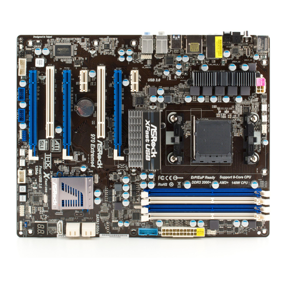
Page 12: Motherboard Layout
USB 2.0 T: USB2 B: USB3 USB 3.0 T: USB4 B: USB5 HD_AUDIO1 Chipset PCIE1 PCIE2 AUDIO CODEC PCI1 SATA3 6Gb/s 970 Extreme4 CMOS PCIE3 BATTERY SB950 Chipset Super PCIE4 SATA3_1 PCI2 FAST USB 32Mb Debug BIOS Front USB 3.0... - Page 13 1.4 I/O Panel PS/2 Mouse Port (Green) USB 3.0 Port (USB45) LAN RJ-45 Port IEEE 1394 Port (IEEE 1394) USB 2.0 Ports (USB23) *** 12 eSATA3 Connector Side Speaker (Gray) USB 2.0 Ports (USB01) Rear Speaker (Black) Clear CMOS Switch (CLRCBTN) Central / Bass (Orange) Optical SPDIF Out Port Line In (Light Blue)
-
Page 15: Installation
2. Installation Pre-installation Precautions... -
Page 16: Installation Of Cpu Fan And Heatsink
2.1 CPU Installation STEP 1: STEP 2 / STEP 3: STEP 4: Match The CPU Golden Triangle Push Down And Lock Lift Up The Socket Lever To The Socket Corner Small The Socket Lever Triangle 2.2 Installation of CPU Fan and Heatsink... -
Page 17: Installation Of Memory Modules (Dimm)
2.3 Installation of Memory Modules (DIMM) identical identical Dual Channel A identical Dual Channel B identical Dual Channel Memory Confi gurations identical... -
Page 18: Installing A Dimm
Installing a DIMM... - Page 19 2.4 Expansion Slots (PCI and PCI Express Slots) PCI Slots: PCIE Slots: Installing an expansion card...
- Page 20 2.5 SLI Operation Guide Requirements 2.5.1 Graphics Card Setup 2.5.1.1 Installing Two SLI -Ready Graphics Cards...
-
Page 21: Driver Installation And Setup
ASRock SLI_Bridge_2S Card 2.5.2 Driver Installation and Setup ® For Windows XP / XP 64-bit OS: ® NVIDIA Settings icon Set SLI and PhysX confi guration Set PhysX GPU acceleration Enabled Select an SLI confi guration Enable SLI Apply... - Page 22 ® For Windows Vista / Vista 64-bit / 7 / 7 64-bit OS: Start All Programs NVIDIA Corporation NVIDIA Control Panel Control Panel Set SLI and PhysX confi guration Set PhysX GPU acceleration Enabled Select an SLI confi guration Enable SLI Apply...
- Page 23 2.6 CrossFireX , 3-Way CrossFireX and Quad CrossFireX Operation Guide 2.6.1 Graphics Card Setup 2.6.1.1 Installing Two CrossFireX -Ready Graphics Cards...
- Page 24 CrossFire Bridge...
- Page 25 2.6.1.2 Installing Three CrossFireX -Ready Graphics Cards...
- Page 26 CrossFire Bridge...
- Page 27 2.6.2 Driver Installation and Setup ® For Windows XP OS: ® For Windows 7 / Vista ATI Catalyst Control Center...
-
Page 28: Surround Display Feature
2.7 Surround Display Feature ..\ Surround Display Information... - Page 29 2.8 ASRock Smart Remote Installation Guide USB 2.0 header (9-pin, blue) CIR header (4-pin, white) USB_PWR DUMMY IRTX IRRX ATX+5VSB 3 CIR sensors in different angles...
- Page 30 2.9 Jumpers Setup Jumper Setting...
-
Page 31: Onboard Headers And Connectors
2.10 Onboard Headers and Connectors USB_PWR DUMMY USB_PWR... - Page 33 PWRBTN (Power Switch): RESET (Reset Switch): PLED (System Power LED): HDLED (Hard Drive Activity LED):...
- Page 34 SPEAKER DUMMY +5V DUMMY +12V CHA_FAN_SPEED FAN_SPEED_CONTROL CHA_FAN_SPEED +12V CHA_FAN_SPEED +12V +12V PWR_FAN_SPEED CPU_FAN_SPEED +12V FAN_SPEED_CONTROL 1 2 3 4...
- Page 35 Pin 1-3 Connected +12V CPU_FAN_SPEED...
-
Page 36: Smart Switches
2.11 Smart Switches... - Page 37 2.12 Dr. Debug Status Code Description...
- Page 41 2.13 Serial ATA3 (SATA3) Hard Disks Installation 2.14 Hot Plug and Hot Swap Functions for SATA3 HDDs NOTE What is Hot Plug Function? What is Hot Swap Function?
- Page 42 2.15 SATA3 HDD Hot Plug Feature and Operation Guide Caution Points of attention, before you process the Hot Plug:...
- Page 43 How to Hot Plug a SATA3 HDD: How to Hot Unplug a SATA3 HDD:...
-
Page 44: Installing Windows
2.16 Driver Installation Guide ® 2.17 Installing Windows 7 / 7 64-bit / Vista Vista 64-bit / XP / XP 64-bit With RAID Functions ® 2.17.1 Installing Windows XP / XP 64-bit With RAID Functions STEP 1: Set up UEFI. STEP 2: Make a SATA3 Driver Diskette. - Page 45 STEP 3: Use “RAID Installation Guide” to set RAID confi guration. .. \ RAID Installation Guide ® STEP 4: Install Windows XP / XP 64-bit OS on your system. ® 2.17.2 Installing Windows 7 / 7 64-bit / Vista Vista 64-bit With RAID Functions STEP 1: Set up UEFI.
- Page 46 ® 2.18 Installing Windows 7 / 7 64-bit / Vista Vista 64-bit / XP / XP 64-bit Without RAID Functions ® 2.18.1 Installing Windows XP / XP 64-bit Without RAID Functions Using SATA3 HDDs with NCQ and Hot Plug functions (AHCI mode) STEP 1: Set up UEFI.
-
Page 47: Untied Overclocking Technology
® 2.18.2 Installing Windows 7 / 7 64-bit / Vista Vista 64-bit Without RAID Functions Using SATA3 HDDs with NCQ and Hot Plug functions (AHCI mode) STEP 1: Set up UEFI. ® STEP 2: Install Windows 7 / 7 64-bit / Vista / Vista 64-bit OS on your system. -
Page 48: Uefi Setup Utility
3. UEFI SETUP UTILITY 3.1 Introduction 3.1.1 UEFI Menu Bar Main OC Tweaker Advanced H/W Monitor Boot Security Exit... -
Page 49: Navigation Keys
3.1.2 Navigation Keys Navigation Key(s) Function Description + / - <Enter> <F1> <F9> <F10> <ESC> 3.2 Main Screen System Time [Hour:Minute:Second] System Date [Day Month/Date/Year]... -
Page 50: Oc Tweaker Screen
3.3 OC Tweaker Screen CPU Confi guration Overclock Mode Spread Spectrum ASRock UCC CPU Active Core Control Processor Maximum Frequency North Bridge Maximum Frequency Processor Maximum Voltage... - Page 51 Multiplier/Voltage Change HT Bus Speed HT Bus Width DRAM Confi guration DRAM Frequency DRAM Timing Control Power Down Enable Bank Interleaving Channel Interleaving...
- Page 52 CAS# Latency (tCL) RAS# to CAS# Delay (tRCD) Row Precharge Time (tRP) RAS# Active Time (tRAS) Command Rate (CR) RAS# Cycle Time (tRC) Write Recovery Time (tWR) Refresh Cyle Time (tRFC) RAS to RAS Delay (tRRD) Write to Read Delay (tWTR) Read to Precharge (tRTP) Four Activate Window (tFAW) Voltage Control...
- Page 53 NB Voltage HT Voltage CPU VDDA Voltage PCIE VDDA Voltage SB Voltage Would you like to save current setting user defaults?
- Page 54 3.4 Advanced Screen Instant Flash...
-
Page 55: Cpu Configuration
3.4.1 CPU Configuration Cool ‘n’ Quiet Secure Virtual Machine Enhance Halt State (C1E) CPU Thermal Throttle... - Page 56 3.4.2 North Bridge Configuration Primary Graphics Adapter IOMMU...
-
Page 57: South Bridge Configuration
3.4.3 South Bridge Configuration Onboard HD Audio Front Panel On/Off Play Onboard LAN Onboard 1394 controller Good Night LED Onboard Debug Port LED... -
Page 58: Storage Configuration
3.4.4 Storage Configuration SATA Controller SATA Mode SATA IDE Combined Mode Hard Disk S.M.A.R.T. -
Page 59: Super Io Configuration
3.4.5 Super IO Configuration Serial Port Serial Port Address Infrared Port Infrared Port Address... -
Page 60: Acpi Configuration
3.4.6 ACPI Configuration Suspend to RAM Check Ready Bit Restore on AC/Power Loss PS/2 Keyboard Power On PCI Devices Power On Ring-In Power On RTC Alarm Power On USB Keyboard/Remote Power On... - Page 61 USB Mouse Power On ACPI HPET table...
-
Page 62: Usb Configuration
3.4.7 USB Configuration USB 2.0 Controller USB 3.0 Controller Legacy USB Support Legacy USB 3.0 Support... -
Page 63: Hardware Health Event Monitoring Screen
3.5 Hardware Health Event Monitoring Screen CPU Fan 1 & 2 Setting Chassis Fan 1 Setting Chassis Fan 2 Setting Chassis Fan 3 Setting... -
Page 64: Boot Screen
3.6 Boot Screen Setup Prompt Timeout Bootup Num-Lock Full Screen Logo AddOn ROM Display Boot Failure Guard Boot Failure Guard Count Boot From Onboard LAN... -
Page 65: Security Screen
3.7 Security Screen... -
Page 66: Exit Screen
3.8 Exit Screen Save Changes and Exit Discard Changes and Exit Discard Changes Load UEFI Defaults Launch EFI Shell from fi lesystem device... -
Page 67: Software Support
4. Software Support 4.1 Install Operating System 4.2 Support CD Information 4.2.1 Running The Support CD 4.2.2 Drivers Menu 4.2.3 Utilities Menu 4.2.4 Contact Information... -
Page 68: Installing Os On A Hdd Larger Than 2Tb
Installing OS on a HDD Larger Than 2TB ® Windows Vista 64-bit (with SP1 or ® above) Windows 7 64-bit AHCI Mode...
Need help?
Do you have a question about the 970 Extreme4 and is the answer not in the manual?
Questions and answers