Table of Contents
Advertisement
Available languages
Available languages
A U X
S P
Before attempting to connect or operate this product,
please read these instructions carefully and save this manual for future use.
No model number suffix is shown in this Operating Instructions.
Operating Instructions
Model No.
A U X
IN
EC HO
CA NC
T A LK
EL LE R
D N R
P A G E
D U A L
LE V E
L
LA N E
B E E P
RE D
LA N E
S E LE
YE LL
M AX
C T
O W M
P O S
G RE EN
D
T E LE
R E M O
P H O N
LO W
O FF
T E
E
C O N
O FF
T X P O
T R O L
IN S T
W E R
O U T
A L L S
Y S T E
M S E
P R E V
T T IN
G
S E L
N E X T
O U T S
ID E
S P
ID R E
M IC
A U X
G IS T
R A T IO
S P
N
B E E P
M IC
P O S
A U D IO
G R E E
O N
T E R
O P E R
S T A R
S P E E
A T IO
T
D
N A L
D E LA
T E A M
B E E P
S E T T
Y
R E C
D A Y /N
IN G
IG H T
O U T S
S E LE
C T
ID E
O N :D
S P LE
1
A Y
V E L
2
V /D E
T
O N :D
O V E R
V O LU
A Y
R ID E
T /P
D O W
M E
R E LE
N
A S E
U P
H E A D
S E T
P LA Y
B A C K
D E S T
IN A T
A U X
IO N
H E A D
S E T
Center Module
WX-C3010
P O W
E R
TA LK
P A G E
V E H IC
LE
D E TE
C TO R
Advertisement
Chapters
Table of Contents

Related Manuals for Panasonic WXC3010 - CENTER MODULE - MULTI LANGUAGE


Summary of Contents for Panasonic WXC3010 - CENTER MODULE - MULTI LANGUAGE
-
Page 1: Operating Instructions
Center Module Operating Instructions WX-C3010 Model No. A U X A U X EC HO CA NC T A LK EL LE R D N R P A G E D U A L LE V E LA N E B E E P RE D LA N E... - Page 2 (2) this device must accept any interference received, including interference that may cause undesired operation. Responsible Party: Panasonic Corporation of North America One Panasonic Way, Secaucus, NJ 07094 Technical Support Party: Panasonic Consumer Electronics Company 1707 N. Randall Rd., Elgin IL. 60123 Technical Support Tel No.:...
- Page 3 WARNING: • This apparatus must be earthed. • Apparatus shall be connected to a main socket outlet with a pro- tective earthing connection. • The mains plug or an appliance coupler shall remain readily operable. • To reduce the risk of fire or electric shock, do not expose this apparatus to rain or moisture.
-
Page 4: Limitation Of Liability
Limitation of Liability THIS PUBLICATION IS PROVIDED "AS IS" WITHOUT WARRANTY OF ANY KIND, EITHER EXPRESS OR IMPLIED, INCLUDING BUT NOT LIMITED TO, THE IMPLIED WARRANTIES OF MERCHANTABILITY, FITNESS FOR ANY PARTICULAR PURPOSE, OR NON-INFRINGEMENT OF THE THIRD PARTY'S RIGHT. Disclaimer of Warranty IN NO EVENT SHALL MATSUSHITA ELECTRIC INDUSTRI- (4) ANY PROBLEM, CONSEQUENTIAL INCONVENIENCE,... -
Page 5: Important Safety Instructions
Important Safety Instructions 1) Read these instructions. 2) Keep these instructions. 3) Heed all warnings. 4) Follow all instructions. 5) Do not use this apparatus near water. 6) Clean only with dry cloth. 7) Do not block any ventilation openings. Install in accordance with the manufacturer's instructions. 8) Do not install near any heat sources such as radiators, heat registers, stoves, or other apparatus (including amplifiers) that produce heat. -
Page 6: Table Of Contents
G Vehicle Detector Normal/Override On ....................15 G Talk/Page Release ..........................15 Installation & Connections ........................16 Panasonic WX-C3010 Series System Parts and Accessories ..............16 Major Operating Controls and Their Functions ..................17 Installations/Connections ........................... 19 I Installation procedures ........................19 I Preparations ............................ -
Page 7: Preface
Preface Center Module WX-C3010 is exclusively designed for Panasonic Wireless Communication System, which is used with drive-thru menu boards, etc. The system operates on 1.9 GHz DECT. Features • 1.9 GHz DECT* is used with center module to prevent the interference from microwave ovens or wireless LAN used with 2.4 GHz DECT. -
Page 8: Precautions
Precautions • Handle this product with care. The product contains sensitive components that can be damaged by improper handling or storage. • Repair or replace any defective components. • Use this product for indoor use only. • Do not expose this product to direct sunlight for hours and do not install the product near a heater or an air conditioner. Otherwise, it may cause deformation, discoloration and malfunction. -
Page 9: Operations
Major Operating Controls and Their Functions I WX-C3010 Center Module CONTROL INDICATORS VOLUME CONTROLS COMMUNICATION INDICATORS OPERATIONAL SETTING GREETER q Power ON/OFF Switch y Telephone Indicator (Green) (TELEPHONE) This switch turns the power of the center module on and When the Order Taker or the All-in-One Headset is set in off. - Page 10 !0 Auxiliary Speaker Volume (AUX, SP) @1 Vehicle Detector Normal/Override On Button This control sets the output level of auxiliary speaker. This button turns the vehicle detector Normal and Override On. !1 Auxiliary Microphone Volume (AUX, MIC) NORMAL: The vehicle detector turns on only when vehi- This control sets the input level of gooseneck micro- cle is detected at the menu board.
- Page 11 @7 Greeter Start Delay Indicator (Yellow) (START DELAY) This indicates that the greeter start delay has selected @8 Greeter Start Delay Button (START DELAY) This button turns the greeter start delay normal and delay. @9 Greeter Record Indicator (Red) (REC) This indicates that while recording in the selected greeter memory (1 or 2).
-
Page 12: Operating Procedures
Operating Procedures I Basic Operation I Convenient Functions G Power ON G Auto Talk Lock Press the Power ON/OFF Switch of the center module to turn When a customer approaches the menu board, it is auto- the power supply ON. matically possible to make the predetermined personnel’s It takes about 5 seconds until the power supply is started. -
Page 13: G Greeter
5. Press the SPEED TEAM button of the Center Module 5. Release the PAGE button at the PTP setting. Press the again, the SPEED TEAM mode will be released. The PAGE button again at the PAGE LOCK setting. Order Taker or All-in-One Headset allows the operator to When recording is complete, one each of the recorded hear the voice prompt of the "SPEED TEAM OFF". -
Page 14: G Vehicle Detector Beep Day/Night
5. When the delay is necessary for the message Note: When the customer approaches the menu board, the • If POS Remote is set for ON, you have to note that no message is output after a delay of 2 seconds. Press the button operation of the Beep Day/Night is possible at the Greeter Start Delay Button of the Center Module. -
Page 15: G Vehicle Detector Normal/Override On
G Vehicle Detector Normal/Override On The Vehicle Detector operation can be set up. Normal/Override On setup can be made by button operation at the front panel of this unit. When the Override On mode is set, the V/D Override indica- tor of the center module will light in yellow. -
Page 16: Installation & Connections
Panasonic WX-C3010 Series System Parts and Accessories Note: Illustrations may differ from actual products. I Center Module I All-in-One Headset I Order Taker WX-C3010 WX-H3050 WX-T3020 AU X AU X ECH O CAN CEL TA LK DN R PA GE... -
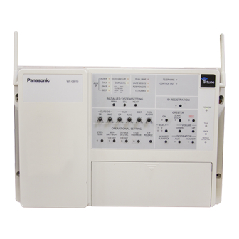
Page 17: Major Operating Controls And Their Functions
Major Operating Controls and Their Functions INSTALLED SYSTEM SETTING ID REGISTRATION q AC Inlet !0 Talk On/Off Indicator (Green) (TALK) w Power On/Off Switch This indicator is toggled ON when the communication e Through-hole between store personnel and a customer is provided r Antenna through the auxiliary speaker. - Page 18 !6 Lane select Indicator (Red/Green) (LANE SELECT) Select the lane A or B at the double drive-thru. Red: Selected Lane A Green: Selected Lane B !7 POS Remote Control Indicator (Green) (POS REMOTE) This item selects the POS remote control On and Off. OFF: POS Remote OFF ON: POS Remote ON !8 TX Power Indicator (Green) (TX POWER)
-
Page 19: Installations/Connections
Installations/Connections I Installation procedures Preparations (Refer to page 19.) Installation of center modules on the wall (Refer to page 19.) Wiring to the center modules (Refer to page 20.) ID registration for follower units (Refer to page 25.) [System Setup] Installed System Setting (Refer to page 26.) Adjustments to adequate sound levels... -
Page 20: I Wiring To The Center Modules
I Wiring to the center modules 1. Remove the terminal cover. Slide the front cover downwards by pressing its arrow- marked part and pull the lower side of the cover toward you. AU X AU X EC HO CA NC TA LK EL LE R PA G E... -
Page 21: I Clamping The Power Plug And Power Cord
I Clamping the Power Plug and 3. Insert the power plug into the power cord inlet. Power Cord 4. Push the holder forward until the holder touches the power plug. Important: Surely clamp the power plug to this center module and screw the AC cable to the wall using the provided AC cable clamper. -
Page 22: I Basic Connection
I Basic Connection This diagram shows the basic system connection. CONNECTOR 1 CONNECTOR 2 ORDER INTERFACE ORDER INTERFACE MENUBOARD SPEAKER Microphone Gooseneck Microphone Speaker VEHICLE DETECTOR EXTENSION EXTERNAL VEHICLE DEVICE DETECTOR *1 OUTPUT: Photocoupler (PS2352L)-isolated, max. 100 mA... -
Page 23: I Pos (Point Of Sales)-System Connection
I POS (Point of sales)-System Connection This diagram shows the connection with the POS system. CONNECTOR 3 CONNECTOR 4 POS INTERFACE POS INTERFACE +12V I /O I / F POS System *1 INPUT: Non-voltage make contact *2 OUTPUT: Photocoupler (PS2501L)-isolated, max. 10 mA... -
Page 24: I Double-Drive-Thru Connection
I Double-Drive-Thru Connection This diagram shows the connection in the double-drive-thru system. Lane A DOUBLE-DRIVE-THRU Use a LAN cable with the shield type Lane B DOUBLE-DRIVE-THRU Use a LAN cable with the shield type... -
Page 25: I Id Registration For Follower Units
I ID registration for follower units • To talk with the headsets (Order Taker and All-in-One Headset), ID registration is required. • For ID registration, set the center module in ID registration mode and make operation of ID registration by means of a follow- er unit. -
Page 26: I Installed System Setting
I Installed System Setting After the completion of installation work, system setup shall be made according to the equipment to be connected and the oper- ation mode. Setup operation for the installed system shall be carried out by the use of the PREV/NEXT button and the SEL button. OFF: Lighting time is short and unlighting time is long. -
Page 27: G Setup Operation For Echo Canceller (Echo Canceller Effect Level Control)
G Setup operation for Echo Canceller (Echo Canceller Effect Level Control) The effect of Echo Canceller (the amount of echo erase) is set up. Echo Canceller Indicator Sound Quality Remarks Level – No Echo Canceller processing Green High When the effect of echo is small, this position is selected. Yellow Normal HIGH... -
Page 28: G Setup Operation For Dual Lane
G Setup operation for Dual Lane In the case of Dual Lane, two menu boards (Lane A and Lane B) are used. Only for the Center Module of Lane B, the Dual Lane is set at ON. ON: DUAL LANE ON (Green) When there are cars in Lane A and B, the greeter memo- When there is car in only Lane B, the greeter memory 1 ry 2 is output to the speaker of Lane B. -
Page 29: G Lane Setup
G Lane setup In the case of Double-Drive-Thru, one each unit of Center Module is set for Lane A and Lane B, respectively. Only for the Center Module of Lane B, the Dual Lane is set at ON. When Lane A or Lane B setup is changed over, the center module will be restarted automatically. If the [TALK] and [PAGE] indicators begin to blink after restarting, check the connections between both center modules. -
Page 30: I Info About Pos Remote Functions
I Info about POS Remote functions Remote control becomes possible if any external device is connected to the POS Remote terminal of the center module. To use the POS Remote functions, POS Remote setup shall be turned ON. (Refer to page 29. ) Functions (Terminal names) Usage V/D OUTPUT... -
Page 31: Maintenance & Specifications
Troubleshooting Reference Symptom Cause/solution pages Is the Power ON/OFF Switch on the center module turned on? The communication among • Check the AC power outlet. the Order Takers, menu board 9, 17 • If the problem remains even after trying the above, refer to the and All-in-One Headset can- dealer or service personnel. - Page 32 Reference Symptom Cause/solution pages Outside speaker and microphone may not be properly installed. • Be sure speaker and microphone are isolated from each – other, and tightly mounted with enough foam packed around each of them to absorb vibrations. Outbound and/or inbound audio level may be set too high. •...
-
Page 33: Specifications
Specifications Operating frequency (TX/RX): 1 920 MHz-1 930 MHz Power supply: 120 V AC, 60 Hz Power consumption: 11 W 1.25 W, 8 Ω Outside speaker: 1.25 W, 8 Ω AUX speaker: Dimensions: 404 mm (W) x 265 mm (H) x 69 mm (D) {15-15/16"... -
Page 34: Standard Accessories
Standard accessories Operating Instructions (this manual) ........ 1 pc. AC cable ................1 pc. AC cable holder ............... 1 pc. Miniture screw driver ............1 pc. AC cable clamper ............1 pc. - Page 35 VERSION FRANÇAISE (FRENCH VERSION) AVERTISSEMENT: • Cet appareil doit être mis à la terre. • Le périphérique doit être connecté à une prise de sortie secteur munie d'une connexion de mise à la terre de sécurité. • La prise de sortie secteur ou l'adaptateur d'alimentation du périphérique doit toujours être prêt à...
-
Page 36: Limitation De Responsabilité
Limitation de responsabilité CETTE PUBLICATION EST FOURNIE "COMME TEL" SANS GARANTIE DE TOUTE SORTE, EXPRÈS OU IMPLICITE, ÉTANT INCLUSE MAIS NON LIMITÉE AUX GARANTIES IMPLICITES DE LA VALEUR MARCHANDE, ADAPTATION POUR TOUT BUT PARTICULIER OU NON-INFRACTION DES DROITS D'UN TIERS. Déni de la garantie EN AUCUN CAS MATSUSHITA ELECTRIC INDUSTRIAL (4) TOUT PROBLÈME, INCOMMODITÉ... -
Page 37: Instructions De Sécurité Importantes
Instructions de sécurité importantes 1) Veiller à lire ces instructions. 2) Conserver ces instructions. 3) Tenir compte de tous les avertissements. 4) Se conformer à toutes les instructions. 5) Ne pas utiliser cet appareil près de lieux en présence d'eau. 6) Nettoyer uniquement avec un chiffon sec. - Page 38 G Activation de détecteur de véhicule normal/asservi ................. 47 G Libération Parler/Page ........................47 Installation et Connexions ........................48 Éléments et accessoires de système des séries WX-CC3010 Panasonic ..........48 Principaux organes de commande et fonctions ..................49 Installations/Connexions ..........................51 I Procédures d'installation ........................
-
Page 39: Préface
Le module central WX-C3010 est exclusivement conçu pour être utilisé avec les systèmes de communication à liaison radio Panasonic dont on se sert dans les tableaux de menu de service clientèle de passage, etc. Le système fonctionne sur 1,9 Ghz DECT. -
Page 40: Mesures De Précaution
Mesures de précaution • Manipuler ce produit sans brutalités. Ce produit renferme des composants extrêmement sensibles qui risquent d'être endommagés à la suite d'une manipulation ou d'un rangement inapproprié. • Réparer ou remplacer tous les composants défectueux. • Ce produit est essentiellement conçu pour un usage sous abri. •... -
Page 41: Opérations
Principaux organes de commande et leurs fonctions I Module central WX-C3010 Indicateurs de commande Commandes de volume Indicateurs de communication Réglage opérationnel Personne d'accueil q Interrupteur d'alimentation marche-arrêt y Indicateur de téléphone (vert) (TELEPHONE) Ce commutateur coupe l'alimentation du module central Quand le preneur de commande ou le combiné... - Page 42 o Volume de microphone extérieur (OUTSIDE, MIC) @1 Bouton d'activation de détecteur de véhicule Cette commande ajuste niveau d'entrée normal/asservi microphone extérieur. Ce bouton active le mode normal de détecteur de véhicule et l'activation asservie. !0 Volume de haut-parleur auxiliaire (AUX, SP) NORMAL: Le détecteur de véhicule se met en fonction Cette commande ajuste le niveau de sortie du haut- uniquement lorsqu'un véhicule est détecté...
- Page 43 @6 Bouton de sélection de mémoire de personne d'accueil (SELECT) Ce bouton sélectionne l'une ou l'autre des mémoires de personne d'accueil. @7 Indicateur de temporisation de démarrage de personne d'accueil (jaune) (START DELAY) Ceci indique que la fonction de temporisation de démarrage personne d'accueil...
-
Page 44: Modes D'utilisation
Modes d'utilisation I Exécution de base I Fonctions commodes G Mise sous tension G Verrouillage automatique pour parler Appuyer sur le commutateur "marche-arrêt" d'alimentation Quand un client s'approche du tableau de menu, il est du module central pour exécuter la mise sous tension. automatiquement possible de permettre au combiné... -
Page 45: G Personne D'accueil
5. Appuyer encore une fois sur le bouton SPEED TEAM du 5. Relâcher le bouton PAGE pendant le paramétrage de module central pour que le mode SPEED TEAM soit PTP. Appuyer encore une fois sur le bouton PAGE lors libéré. Le preneur de commande ou le combiné du paramétrage de PAGE LOCK. -
Page 46: G Détecteur De Véhicule Beep Day/Night
5. Quand une temporisation est nécessaire pour le Remarque: message • Si POS à distance est paramétré pour ON, noter Quand le client s'approche du tableau de menu, le qu'aucune commande du bouton Diurne-nocturne de message est délivré après un délai de 2 secondes. bip n'est possible au niveau du module central. -
Page 47: G Activation De Détecteur De Véhicule Normal/Asservi
G Activation de détecteur de véhicule normal/asservi Le fonctionnement de détecteur de véhicule peut être configuré. La configuration d'activation Normal/asservi peut être faite en actionnant le bouton implanté sur panneau frontal de cet appareil. Quand le mode d'activation Asservi est paramétré, l'indicateur asservi V/D du module central s'allumera en jaune. -
Page 48: Installation Et Connexions
Éléments et accessoires de système des séries WX-CC3010 Panasonic Remarque: Les illustrations risquent d'être sensiblement différentes des produits réels. I Module central I Combiné microcasque d'écoute I Preneur de commande WX-C3010 tout intégré WX-H3050 WX-T3020 AU X AU X ECH O... -
Page 49: Principaux Organes De Commande Et Fonctions
Principaux organes de commande et fonctions Paramétrage de système installé Enregistrement d'identification q Prise d'entrée d'alimentation à courant alternatif !0 Indicateur marche-arrêt Parle (vert) (TALK) w Interrupteur d'alimentation marche-arrêt Cet indicateur bascule sur ON quand la communication e Ouverture traversante entre le personnel du magasin et un client est assurée r Antenne par le haut-parleur auxiliaire. - Page 50 !6 Indicateur de sélection de passage (rouge/vert) (LANE SELECT) Sélectionner le passage A ou B dans un système double de service clientèle de passage. Rouge: Passage A sélectionné Vert: Passage B sélectionné !7 Indicateur de commande à distance POS (Vert) (TX POS) Cette rubrique sélectionne l'activation et la désactivation de commande à...
-
Page 51: Installations/Connexions
Installations/Connexions I Procédures d'installation Préparatifs (se référer à la page 51.) Installation des modules centraux sur le mur (Se référer à la page 51.) Câblage aux modules centraux (Se référer à la page 52.) Enregistrement d'identification pour les appareils suivants (Se référer à... -
Page 52: I Câblage Aux Modules Centraux
I Câblage aux modules centraux 1. Retirer le couvercle du tableau de connexion. Faire coulisser le couvercle frontal vers le bas tout en appuyant sur la partie indiquée par une flèche et tirer sur la partie inférieure du couvercle vers soi. AU X AU X EC HO... -
Page 53: I Attache De La Prise D'alimentation Et Du Cordon D'alimentation Secteur
I Attache de la prise 3. Introduire la prise d'alimentation dans la prise d'entrée du cordon d'alimentation. d'alimentation et du cordon 4. Repousser le dispositif de fixation en avant jusqu'à ce d'alimentation secteur dispositif fixation touche prise d'alimentation. Important: Fixer fermement la prise d'alimentation à ce module central et visser le câble d'alimentation secteur au mur à... -
Page 54: I Connexions De Base
I Connexions de base Ce schéma indique la connexion d'un système de base. CONNECTOR 1 CONNECTOR 2 ORDER INTERFACE ORDER INTERFACE Tableau de menu Haut-parleur Microphone Col de cygne de microphone Haut-parleur Détecteur de véhicule Extension de Périphérique détecteur de externe véhicule *1 OUTPUT: Photocoupleur (PS2352L) - isolé, maxi. -
Page 55: I Pos (Points De Ventes)-Connexion De Système
I POS (Points de ventes)-Connexion de système Ce schéma indique la connexion à un système POS. CONNECTOR 3 CONNECTOR 4 POS INTERFACE POS INTERFACE +12V I /O I / F Systèmes POS *1 INPUT: Entrée faisant contact sans tension *2 OUTPUT: Photocoupleur (PS2501L) - isolé, maxi. 10 mA... -
Page 56: I Connexion De Système Double De Service Clientèle De Passage (Double-Drive-Thru)
I Connexion de système double de service clientèle de passage (Double-Drive-Thru) Ce schéma indique la connexion dans un système double de service clientèle de passage. Passage A DOUBLE-DRIVE-THRU Use a LAN cable with the shield type Passage B DOUBLE-DRIVE-THRU Use a LAN cable with the shield type... -
Page 57: I Enregistrement D'identification Pour Les Appareils Suivants
I Enregistrement d'identification pour les appareils suivants • Pour pouvoir parler avec les combinés microcasque d'écoute (preneur de commande ou combiné microcasque d'écoute tout intégré), un enregistrement d'identification est exigé. • En ce qui concerne l'enregistrement d'identification, paramétrer le module central en mode d'enregistrement d'identification et exécuter l'opération d'enregistrement d'identification au moyen de l'appareil suivant. -
Page 58: I Paramétrage De Système Installé
I Paramétrage de système installé Après l'accomplissement des travaux d'installation, la configuration du système doit être faite selon l'équipement à connecter et le mode de fonctionnement souhaité. Les opérations de configuration pour le système installé seront effectuées par l'utilisation du bouton PREV/NEXT et du bouton SEL. -
Page 59: G Opération De Configuration De L'éliminateur D'écho (Contrôle De Niveau D'effet D'éliminateur D'écho)
G Opération de configuration de l'éliminateur d'écho (contrôle de niveau d'effet d'éliminateur d'écho) L'effet de l'éliminateur d'écho (le taux d'effacement d'écho) est configuré. Niveau Qualité Indicateur d'éliminateur Observations acoustique d'écho – Aucun traitement de l'éliminateur d'écho Vert Élevée Quand l'effet de l'écho est faible, cette position est sélectionnée. -
Page 60: G Opération De Configuration De Double Passage
G Opération de configuration de double passage Dans le cas d'un double passage, deux tableaux de menu (passage A et passage B) sont utilisés. Seulement pour le module central du passage B, le double passage est paramétré sur ON. Activé: DUAL LANE ON (Vert) Quand il y a des voitures dans le passage A et le Quand il y a voiture uniquement dans le passage B, la passage B, la mémoire de personne d'accueil 2 est... -
Page 61: G Configuration De Passage
G Configuration de passage Dans le cas d'un système double de service clientèle de passage, chaque appareil du module central est respectivement paramétré pour le passage A ou le passage B. Seulement pour le module central du passage B, le double passage est paramétré sur ON. Quand la configuration du passage A ou du passage B est permutée, le module central sera relancé... -
Page 62: I Information Au Sujet Des Fonctions De Commande À Distance Pos
I Information au sujet des fonctions de commande à distance POS Une commande à distance devient possible si tout périphérique externe est connecté à la prise de connexion de commande à distance POS du module central. Pour utiliser les fonctions de commande à distance POS, la configuration de commande à distance POS sera activée. -
Page 63: Maintenance Et Caractéristiques Techniques
Dépannage Pages de Symptôme Origine/Solution référence L'interrupteur d'alimentation "marche-arrêt" du module central La communication entre les est-il actif ? preneurs de commande, le • Vérifier la prise de sortie secteur. tableau de menu et le 41, 49 • Si le problème subsiste même après avoir essayé les combiné... - Page 64 Pages de Symptôme Origine/Solution référence Le haut-parleur et le microphone externes ne peuvent être installés correctement. • S'assurer que le haut-parleur et le microphone sont isolés – l'un de l'autre et sont solidement installés avec suffisamment de mousse synthétique entourée autour de chacun d'eux afin d'absorber les vibrations.
-
Page 65: Caractéristiques Techniques
Caractéristiques techniques Fréquence d'utilisation (TX/RX): 1 920 MHz-1 930 MHz Alimentation: 120 V c.a., 60 Hz Puissance consommée: 11 W 1,25 W, 8 Ω Haut-parleur extérieur: 1,25 W, 8 Ω Haut-parleur AUX: Dimensions: 404 mm (L) x 265 mm (H) x 69 mm (P) {15-15/16"... -
Page 66: Accessoires Standard
Accessoires standard Manuel d'utilisation (cette documentation) ......... 1 él. Câble d'alimentation secteur ............1 él. Dispositif de fixation d'alimentation secteur 1 él. Tournevis miniature ..............1 él. Attache de câble d'alimentation secteur ........1 él. - Page 68 Panasonic System Solutions Company, Panasonic Sales Company Division of Panasonic Puerto Rico Inc. Unit Company of Panasonic Corporation of North America San Gabriel Industrial Park 65th Infantry Ave. KM. 9.5 www.panasonic.com/business/ Carolina For customer support, call 1.800.528.6747 P.R. 00985(809)750-4300 Three Panasonic Way 2H-2, Secaucus, New Jersey 07094 Panasonic Canada Inc.