Table of Contents
Advertisement
Available languages
Available languages
KAC-6402
4/3/2 CHANNEL POWER AMPLIFIER 7 page 2-13
INSTRUCTION MANUAL
AMPLIFICATEUR DE PUISSANCE 4/3/2 CANAUX 7 page 14-25
MODE D'EMPLOI
AMPLIFICADOR DE POTENCIA DE 4/3/2 CANALES 7 página 26-37
MANUAL DE INSTRUCCIONES
Take the time to read through this instruction manual.
Familiarity with installation and operation procedures will help
you obtain the best performance from your new power amplifier.
For your records
Record the serial number, found on the back of the unit, in the spaces
designated on the warranty card, and in the space provided below.
Refer to the model and serial numbers whenever you call upon your
KENWOOD dealer for information or service on the product.
Model KAC-6402
Serial number
© B64-3045-00/00 (KV/EV)
Advertisement
Table of Contents

Related Manuals for Kenwood KAC-6402


Summary of Contents for Kenwood KAC-6402
- Page 1 Record the serial number, found on the back of the unit, in the spaces designated on the warranty card, and in the space provided below. Refer to the model and serial numbers whenever you call upon your KENWOOD dealer for information or service on the product. Model KAC-6402 Serial number...
-
Page 2: Safety Precautions
NOTE • If you experience problems during installation, consult your Kenwood dealer. • If the unit does not seem to be working right, consult your Kenwood dealer. This Product is not installed by the manufacturer of a vehicle on the production line, nor by the professional importer of a vehicle into an EU Member State. - Page 3 Installation Self-tapping screw (ø4 × 16 mm) 330 mm 231 mm Ø4.6 Installation board, etc. (thickness : 15 mm or more) CAUTION • Do not install in the below locations; (Unstable location, In a location that interferes with driving, In a location that gets wet, In a dusty location, In a place that gets hot, In a place that gets direct sunlight, In a location that gets hit by hot air) •...
- Page 4 Controls / Indicator 1 FILTER switch (A.ch/B.ch) 5 INPUT SENSITIVITY control (A.ch/B.ch) This switch allows to apply high-pass or low-pass Set this control according to the pre-output level filtering to the speaker outputs. of the center unit connected with this unit, or to the maximum power output of the genuine- •...
-
Page 5: Power Indicator
■ The protection function is activated in 6 Power indicator When the power is turned on, the Power the following situations: indicator lights. This unit is equipped with a protection function If the Power indicator does not light when the for protecting this unit and your speakers from power is turned on, the protection function various accidents or problems that can occur. -
Page 6: Speaker Output Terminals
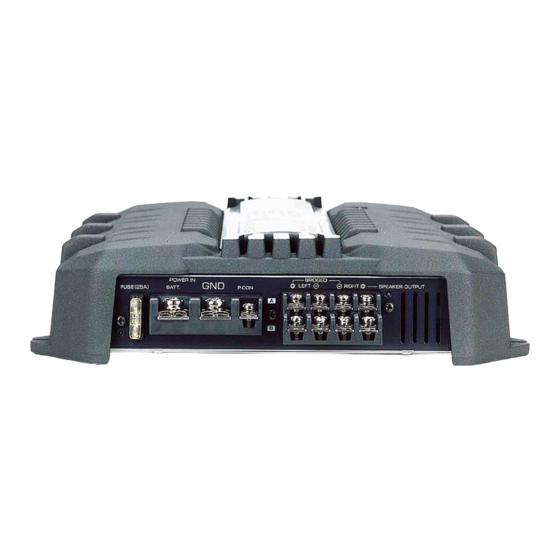
Connection ■ Terminal names 7 Fuse (25 A) # RCA cable ground lead terminal When using an RCA cable with a ground lead 8 Battery terminal attached, connect the ground lead to this 9 Ground terminal terminal. 0 Power control terminal $ Speaker level input terminals Controls the unit ON/OFF. -
Page 7: Installation Procedure
■ Installation procedure ■ Wiring Since there are large variety of settings and • Take the battery wire for this unit directly from the connections possible according to applications, read battery. If it's connected to the vehicle’s wiring the instruction manual well to select the proper harness, it can cause blown fuses etc. - Page 8 Connection ■ RCA cable or Speaker level input connection (RCA cable Connections) RCA cable* CENTER UNIT (CD receiver, etc.) Power control wire (Blue/ White) A channel input B channel input RCA cable ground terminal Speaker level input cable (Speaker level input Connections) Cable Color of the connector White A channel...
- Page 9 * Commercially available parts ■ Speaker wire connection (Stereo Connections) A channel Left speaker A channel Lead terminal* Right speaker B channel Right speaker B channel Left speaker (Bridged Connections) A channel Speaker (Bridged) B channel Speaker (Bridged) ■ Power wire connection Lead terminal* Terminal cover Power control wire...
-
Page 10: System Examples
System examples ■ 4-channel system Front Left speaker CENTER UNIT Front Right speaker Rear Left speaker Rear Right speaker ■ High-power 2-channel system Left speaker (Bridged) CENTER UNIT Right speaker (Bridged) ■ 2-channel + Subwoofer system (1) Left speaker (High pass) CENTER UNIT Right speaker (High pass) Subwoofer (L + R) (Bridged) - Page 11 ■ Tri-mode Subwoofer (High pass) CENTER UNIT (L + R) (Bridged) ● Principle of Tri-mode Method of frequency band division using a coil and capacitor…in case of 6dB/oct. slope Coil (L): Passes low frequencies and blocks high frequencies. Crossover Frequency (Low pass) 0 dB Capacitor (C): Passes high frequencies and blocks low...
-
Page 12: Troubleshooting Guide
Troubleshooting Guide What might appear to be a malfunction in your unit may just be the result of slight misoperation or miswiring. Before calling service, first check the following table for possible problems. PROBLEM POSSIBLE CAUSE SOLUTION No sound. • Input (or output) cables are •... -
Page 13: Specifications
Specifications Specifications subject to change without notice. Audio Section Max Power Output .......................................400 W Rated Power Output Normal (4 Ω) (20 Hz – 20 kHz, 0.08 % THD) ...........................35 W x 4 Normal (4 Ω) (DIN : 45324 , +B = 14.4V) ............................35 W x 4 Normal (2 Ω) (1 kHz, 0.8 % THD) ................................50 W x 2 Bridged (4 Ω) (1 kHz, 0.8 % THD) ............................... -
Page 14: Précautions De Sécurité
REMARQUE • Si vous rencontrez des problèmes pendant l'installation, consultez votre revendeur Kenwood. • Si l'appareil semble ne pas fonctionner correctement, consultez votre revendeur Kenwood. Ce produit n’est pas installé par le constructeur d’un véhicule sur le site de production, ni par l’importateur... -
Page 15: Installation
Installation Vis taraudeuse (ø4 × 16 mm) 330 mm 231 mm Ø4.6 Tableau d'installation, etc. (épaisseur: 15 mm ou plus) 2ATTENTION • Ne pas procéder à l’installation de l’appareil si vous vous trouvez dans l’un des lieux suivants : (Lieu instable, Lieu où la conduite du véhicule peut être gênée, Lieu exposé à l’humidité, Lieu exposé à la poussière, Lieu surchauffé, Lieu exposé... - Page 16 Contrôles / Indicateur 1 Commutateur FILTER (A.ch/B.ch) 4 Commande FILTER FREQUENCY(A.ch/ B.ch) Ce commutateur permet d'effectuer un filtrage des graves, ou des aigus, appliqués vers les haut- Cette commande permet de préciser la parleurs. fréquence de coupure quand le commutateur FILTER est sur la position LPF ou HPF.
- Page 17 ■ La fonction de protection se met en 6 Indicateur Power Lorsque l’alimentation est activée, l’indicateur service dans les cas suivants POWER s’illumine. Cet appareil est pourvu d’une fonction de Si l’indicateur POWER ne s’illumine pas lorsque protection de l’appareil lui-même et des haut- l’alimentation est activée, la fonction de parleurs de manière à...
- Page 18 Raccordements ■ Noms des terminaux 7 Fusible (25A) ATTENTION 8 Borne BATT (alimentation) La puissance admissible par les haut-parleurs 9 Borne GND (masse) doit être au moins égale à la puissance de sortie de l'amplificateur. Dans le cas contraire, une 0 Borne P.CON (fil de commande anomalie de fonctionnement peut survenir.
- Page 19 ■ Procédure d'installation ■ Câblage • Pour cette unité, brancher le cordon de la batterie Etant donné que le nombre de réglages et de directement à la batterie. Si celui-ci est connecté à raccordements est assez important, il importe l’installation électrique du véhicule, l’installation peut de prendre pleinement connaissance du mode disjoncter etc.
- Page 20 Raccordements ■ Câble RCA ou connexion d'entrée de niveau d'enceinte (Raccordement d'un câble à fiche Cinch (RCA)) Câble RCA* Unité centrale (récepteur/ lecteur de CD, etc.) Câble de commande de l’alimentation (Bleu/Blanc) Entrée A canal Entrée B canal Borne de masse pour câble RCA Câble d'entrée de niveau (Raccordement au niveau haut-parleur) d'enceinte...
- Page 21 * disponible dans le commerce ■ Connexion des câbles d’haut-parleur (Connexions stéréo) A canal Haut-parleur gauche A canal Cosse pour câble* Haut-parleur droit B canal Haut-parleur droit B canal Haut-parleur gauche (Connexions en pont) A canal Haut-parleur (Pont) B canal Haut-parleur (Pont) ■...
-
Page 22: Exemple De Configuration
Exemple de configuration ■ Système 4 voies Haut-parleur avant gauche Unité centrale Haut-parleur avant droit Haut-parleur arrière gauche Haut-parleur arrière droit ■ Système 2 voies, puissance élevée Haut-parleur gauche (Pont) Unité centrale Haut-parleur droit (Pont) ■ Système 2 voies + enceinte d'extrêmes graves (1) Haut-parleur gauche (filtre passe-haut) Unité... - Page 23 ■ Le Tri-mode Haut-parleurs (filtre passe- d'extrêmes graves Unité centrale haut) (L+R) (Pont) ● Principle of Tri-mode Méthode de division de la bande des basses fréquences au moyen d’une bobine et d’un condensateur ... dans le cas d’une pente de 6dB/oct. Self (L) : Elle laisse passer les frequences graves mais bloque Fréquence de recoupement les fréquences aiguës (filtre passe-bas).
-
Page 24: Guide De Depannage
Guide de depannage Ce qui peut apparaître comme un mauvais fonctionnement de votre appareil n’est peut être que le résultat d’une mauvaise opération ou d’une mauvaise connexion. Avant d’appeler un centre de service, vérifiez d’abord dans le tableau suivant les problèmes possibles. PROBLEME CAUSE POSSIBLE SOLUTION... -
Page 25: Spécifications
Spécifications Les spécifications sont sujettes à changements sans notification. Section audio Puissance de sortie max....................................400 W Puissance de sortie norminale Normal (4 Ω) (20 – 20 kHz, 0,08 % THD) ............................35 W x 4 Normal (4 Ω) (DIN : 45324 , +B = 14,4V) ............................35 W x 4 Normal (2 Ω) (1 kHz, 0,8 % THD) ................................50 W x 2 En pont (4 Ω) (1 kHz, 0,8 % THD) ............................... -
Page 26: Precauciones De Seguridad
• Si tiene problemas durante la instalación, consulte con su distribuidor Kenwood. • Si la unidad no está funcionando correctamente, consulte con su distribuidor Kenwood. Este producto no ha sido instalado en la línea de producción por el fabricante de un vehículo, ni tampoco por el importador profesional de un vehículo dentro del estado miembro de la UE. -
Page 27: Instalación
Instalación Tornillo autorroscantes (ø4 × 16 mm) 330 mm 231 mm Ø4.6 Tablero de instalación, etc. (grosor: 15 mm o más) PRECAUCIÓN • No instale el equipo en las siguientes ubicaciones; (Ubicación inestable; En un lugar que interfiera a la conducción; En un lugar en el que pueda mojarse; En un lugar con exceso de polvo;... - Page 28 Controles / Indicador 4 Control FILTER FREQUENCY (A.ch/B.ch) 1 Conmutador FILTER (A.ch/B.ch) Este conmutador permite aplicar la filtración Ajusta la frecuencia de corte cuando el de paso alto o paso bajo a las salidas de los conmutador FILTER está en LPF o HPF. altavoces.
- Page 29 ■ La función de protección se activa en los 6 Indicador POWER Cuando la alimentación se activa, el indicador de casos siguientes: POWER se ilumina. Este aparato está equipado con una función Si el indicador de POWER no se ilumina al activar de protección que protege el aparato y los la alimentación, la función de protección puede altavoces de diversos accidentes y problemas...
-
Page 30: Conexiones
Conexiones ■ Nombres de los terminales 7 Fusible (25A) PRECAUCIÓN 8 Terminal BATT (alimentación) La entrada nominal de los altavoces no deberá ser inferior a la salida máxima del amplificador. 9 Terminal GND (tierra) De lo contrario podría producirse una falla en el 0 Terminal del control de corriente (P.CON) funcionamiento. - Page 31 ■ Procedimiento de instalación ■ Cableado Como se puede hacer una gran variedad de ajustes y • Lleve el cable de la batería de esta unidad conexiones según las aplicaciones, lea atentamente directamente desde la propia batería. Si se el manual de instrucciones para seleccionar el ajuste conectara al arnés del cableado del vehículo, puede y la conexión apropiados.
- Page 32 Conexiones ■ Conexión de entrada del cable RCA o del nivel del altavoz (Conexión de cable de RCA) Cable RCA* APARATO CENTRAL (reproductor de discos compactos, etc.) Cable de control de potencia (Azul/blanco) Entrada A canal Entrada B canal Terminal del cable de masa del cable RCA Cable de entrada del nivel de (Conexión para entrada de altavoz) altavoces...
- Page 33 * pieza de venta en el comercio especializado ■ Conexión del cable de los altavoces (Conexiones estereofónicas) A canal Altavoz izquierdo A canal Terminal de cable* Altavoz derecho B canal Altavoz derecho B canal Altavoz izquierdo (Conexiones en puente) A canal Altavoz (Puenteada) B canal Altavoz (Puenteada)
- Page 34 Ejemplos del sistema ■ Sistema de 4 canales Altavoz delantero izquierdo APARATO CENTRAL Altavoz delantero derecho Altavoz trasero izquierdo Altavoz trasero derecho ■ Sistema de 2 canales de alta potencia Altavoz izquierdo (Puenteada) APARATO CENTRAL Altavoz derecho (Puenteada) ■ Sistema de 2 canales + Altavoz de subgraves (1) Altavoz izquierdo (Paso alto) APARATO CENTRAL...
- Page 35 ■ Tri-modo Altavoz de subgraves APARATO (Paso alto) (L + R) (Puenteada) CENTRAL ● Propiedades de las bobinas y de los capacitores Método de división de bandas de frecuencias utilizando una bobina y un capacitor ... en el caso de una inclinación de 6 dB/octava Frecuencia de cruce Bobina (L): Deja paso a las bajas frecuencias y bloquea las altas frecuencias.
-
Page 36: Guia Sobre Localización De Averias
Guia Sobre Localización De Averias Lo que podría parecer una falla de funcionamiento de su unidad podría ser simplemente el resultado de un pequeño error de operación o de un defecto de conexión. Antes de acudir al servicio, verifique primero el siguiente cuadro sobre los problemas que se podrían presentar. -
Page 37: Especificaciones
Especificaciones Las especificaciones se encuentran sujetas a cambios sin previo aviso. Sección de audio Máxima potencia de salida .....................................400 W Salida de potencia nominal Normal (4 Ω) (20 Hz – 20 kHz, 0,08 % de distorsión armónica total) ................35 W x 4 Normal (4 Ω) (DIN : 45324 , +B = 14.4V) ............................35 W x 4 Normal...
Need help?
Do you have a question about the KAC-6402 and is the answer not in the manual?
Questions and answers