Chamberlain LiftMaster CSW24V Installation Manual
Elite series vehicular swing gate operator
Hide thumbs
Also See for LiftMaster CSW24V:
- Quick start manual (2 pages) ,
- User manual (8 pages) ,
- Manual (1 page)
Table of Contents
Advertisement
CSW24V™ & CSW24VH™
VEHICULAR SWING GATE OPERATOR
I N S T A L L A T I O N M A N U A L
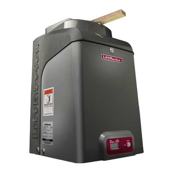
Your model may look different than the model illustrated in this manual.
THIS PRODUCT IS TO BE
INSTALLED AND SERVICED BY A
TRAINED GATE SYSTEMS
TECHNICIAN ONLY.
Visit www.liftmaster.com to
locate a professional installing
dealer in your area.
UL325
compliant
This model is for use on
vehicular passage gates ONLY
and not intended for use on
pedestrian passage gates.
This model is intended for use in
Class I, II, III and IV vehicular
swing gate applications.
UL991
compliant
Advertisement
Table of Contents
Troubleshooting

Related Manuals for Chamberlain LiftMaster CSW24V


Summary of Contents for Chamberlain LiftMaster CSW24V
- Page 1 CSW24V™ & CSW24VH™ VEHICULAR SWING GATE OPERATOR I N S T A L L A T I O N M A N U A L Your model may look different than the model illustrated in this manual. This model is for use on...
-
Page 3: Table Of Contents
TABLE OF CONTENTS SAFETY PROGRAMMING Safety Symbol and Signal Word Review ....... . 1 Remote Controls . -
Page 4: Ul325 Model Classifications
SAFETY UL325 MODEL CLASSIFICATIONS UL325 MODEL CLASSIFICATIONS CLASS I – RESIDENTIAL VEHICULAR GATE OPERATOR A vehicular gate operator (or system) intended for use in a home of one-to four single family dwellings, or a garage or parking area associated therewith. CLASS II –... -
Page 5: Safety Installation Information
SAFETY SAFETY INSTALLATION INFORMATION SAFETY INSTALLATION INFORMATION 1. Vehicular gate systems provide convenience and security. Gate systems are 8. Controls intended for user activation must be located at least 6 feet (1.8 m) comprised of many component parts. The gate operator is only one component. away from any moving part of the gate and where the user is prevented from Each gate system is specifically designed for an individual application. -
Page 6: Gate Construction Information
SAFETY GATE CONSTRUCTION INFORMATION GATE CONSTRUCTION INFORMATION Vehicular gates should be installed in accordance with ASTM F2200: Standard Specification for Automated Vehicular Gate Construction. For a copy, contact ASTM directly at 610-832-9585 or www.astm.org. GENERAL REQUIREMENTS 3.1.3 A gap, measured in the horizontal plane parallel to the roadway, between a fixed stationary object nearest the roadway, (such as a gate support post) Gates shall be constructed in accordance with the provisions given for the and the gate frame when the gate is in either the fully open position or the... -
Page 7: Required Entrapment Protection Devices
SAFETY REQUIRED ENTRAPMENT PROTECTION DEVICES REQUIRED ENTRAPMENT PROTECTION DEVICES To prevent SERIOUS INJURY or DEATH from a moving gate: • Locate entrapment protection devices to protect between moving gate and RIGID objects, such as posts or walls. • Entrapment protection devices MUST be installed to protect anyone who may come near a moving gate. -
Page 8: Important Safety Information
SAFETY IMPORTANT SAFETY INFORMATION IMPORTANT SAFETY INFORMATION INSTALLATION To prevent SERIOUS INJURY or DEATH from a moving gate: • Entrapment protection devices MUST be installed to protect anyone who may come near a moving gate. • Pinch points must be guarded at all times. Install enclosed-style gate tracks and roller guards. - Page 9 • To reduce the risk of FIRE or INJURY to persons use ONLY LiftMaster part • ALWAYS keep people and objects away from the gate. NO ONE SHOULD CROSS 29-NP712 for replacement batteries.
-
Page 10: Introduction
Heater Draw (Optional): 325 watts (120 Vac ONLY) Input Rating: Maximum Gate Weight/Length: • CSW24V: 10 Amps at 120 Vac or 2 Amps at 240 Vac • 1200 lbs./12 foot • CSW24VH: 12 Amps at 120 Vac • 800 lbs./16 foot Input Rating Excluding Accessory Outlets: •... -
Page 11: Features
INTRODUCTION FEATURES FEATURES OPERATOR FEATURES • Advanced “Centerpiece” Control Board • Manual - Secure power failure selection • EMI AC Power Surge Protection and Filter Board • SAMS compatible - Main AC voltage input selection: 120 Vac (factory setting) or 240 Vac (field •... -
Page 12: Preparation
PREPARATION SITE PREPARATION Check the national and local building codes BEFORE installation. GATE CONDUIT & CONCRETE PAD Gate must be constructed and installed according to ASTM F2200 standards (refer Conduit must be UL approved for low and high voltage. Consider the operator to page 4). - Page 13 SITE PREPARATION SAFETY SAFETY Entrapment protection devices are required to protect against any entrapment or safety conditions encountered in your gate application (refer to page 5 for more STANDARD INSTALLATION details). Install warning signs on both sides of the gate. (Inside Property) The illustration is an example of a standard installation.
-
Page 14: Installation
INSTALLATION STANDARD INSTALLATION ONLY STANDARD INSTALLATION ONLY CONDUIT LOCATION MOUNTING FOOTPRINT For compact installation start on page 14. 5.5” 1” DETERMINE LOCATION FOR CONCRETE PAD AND 4.5” 13.6” OPERATOR 6.5” 4” 12.2” DO NOT run the operator until instructed. 6.1” (Conduit) Below is a recommended guide for positioning the concrete pad: 3”... - Page 15 INSTALLATION STANDARD INSTALLATION ONLY STANDARD INSTALLATION ONLY POSITION THE GATE BRACKET NOTE: It may be necessary to attach horizontal reinforcement to the gate before attaching the gate bracket. Position the operator arm onto the output shaft so that the pin slides into the slot.
-
Page 16: Compact Installation Only
INSTALLATION COMPACT INSTALLATION ONLY COMPACT INSTALLATION ONLY DETERMINE LOCATION FOR CONCRETE PAD AND TOP VIEW OF OPERATOR AND GATE OPERATOR Gate Hinge Center DO NOT run the operator until instructed. Refer to the illustration to determine the measurements and location of the concrete pad. -
Page 17: Compact Installation Only
INSTALLATION COMPACT INSTALLATION ONLY COMPACT INSTALLATION ONLY SHORTEN THE OPERATOR ARM For a compact installation the operator arm will have to be shortened. Take the operator arm apart and remove the inner sleeves from the outer tubing. Cut the outer tubing of the operator arm sections to the lengths shown. Put the arm back together and adjust the arm to the measurements as long arm section shown. -
Page 18: Installation Continued
INSTALLATION INSTALLATION CONTINUED... INSTALLATION CONTINUED... WELD THE OPERATOR ARM Once the operator arm measurements are verified: Weld the gate bracket to the gate. Weld the short arm section. Weld the long arm section. Remove the set screws from the arm. NOTE: Completely weld around the outer tubing and bracket. -
Page 19: Wiring
WIRING WIRE THE ENTRAPMENT PROTECTION DEVICES + EARTH GROUND ROD WIRE THE ENTRAPMENT PROTECTION DEVICES Entrapment protection devices are required. Refer to page 5 for more information regarding application. To prevent SERIOUS INJURY or DEATH from a moving gate: • Entrapment protection devices MUST be installed to protect anyone who may •... -
Page 20: Power Wiring
WIRING POWER WIRING POWER WIRING NUMBER OF CYCLES PER DAY This operator can be wired for either 120 Vac or 240 Vac or a solar Swing Gate Installation (12 ft. 800 lb. gate) panel (not provided). Follow the directions according to your application. Accessories Single Gate For dual gate applications, power will have to be connected to each... - Page 21 10W solar panels in series and two 7AH batteries are recommended. For Zone 3 cold weather sites, two 33AH batteries are recommended. We recommend LiftMaster low power draw accessories to minimize power draw, refer to accessory page.
-
Page 22: Dual Gates Only
WIRING DUAL GATES ONLY DUAL GATES ONLY There are two options for dual gate communication: wired or wireless. Follow the directions according to your application. Do not use wired and wireless communication simultaneously. Wired dual gate applications will have a longer battery standby time than wireless applications. WIRED DUAL GATES Before digging, contact local underground utility locating companies. - Page 23 WIRING DUAL GATES ONLY DUAL GATES ONLY WIRELESS DUAL GATES Turn on power to the operator. TO ACTIVATE THE WIRELESS FEATURE: Choose an operator to be the network primary operator. All wireless accessories will need to be programmed to the primary operator. Press and release the LEARN RADIO button on the primary operator.
-
Page 24: Connect Batteries
WIRING DUAL GATES ONLY + CONNECT BATTERIES DUAL GATES ONLY BIPART DELAY/SYNCHRONIZED CLOSE The LOCK/BIPART DELAY switch is used only with dual gate applications and serves two functions: • BIPART DELAY SWING GATE APPLICATIONS: The BIPART DELAY is used in applications where a mag-lock, solenoid lock, or decorative overlay would require one gate to close before the other. - Page 25 WIRING CONNECT BATTERIES CONNECT BATTERIES 33AH BATTERIES The batteries are charged in the circuit by the integrated transformer. The batteries are for battery backup or solar installation. The 33AH application requires the 33AH battery harness (Model K94-36596) and an additional battery tray (Model K10- Outlet Housing 36183) to allow more space in the enclosure.
-
Page 26: Adjustment
ADJUSTMENT LIMIT AND FORCE ADJUSTMENT LIMIT AND FORCE ADJUSTMENT To reduce the risk of SEVERE INJURY or DEATH: • Without a properly installed safety reversal system, persons (particularly small • If one control (force or travel limits) is adjusted, the other control may also children) could be SERIOUSLY INJURED or KILLED by a moving gate. -
Page 27: Obstruction Test
ADJUSTMENT LIMIT AND FORCE ADJUSTMENT + OBSTRUCTION TEST FINE TUNE THE FORCE The FORCE DIAL on the control board is used for fine tuning the force in cases where wind or environmental changes may affect the gate travel. XMITTER Based on the length and weight of the gate it may be necessary to make additional NETWORK force adjustments. -
Page 28: Programming
PROGRAMMING REMOTE CONTROLS + ERASE ALL CODES REMOTE CONTROLS A total of 50 Security✚ 2.0™ remote controls and 2 keyless entries (1 PIN for each keyless entry) can be programmed to the operator. NOTE: When the memory is full the operator will exit programming mode and the remote control/keyless entry will not be programmed. -
Page 29: Finish Installation
FINISH INSTALLATION INSTALL THE COVER INSTALL THE COVER The operator cover consists of two pieces: a rear cover and a front cover. The front cover can easily be removed to access the electrical box. To access the reset switch slide the access door up. -
Page 30: Operation
OPERATION MANUAL DISCONNECT + RESET SWITCH + REMOTE CONTROL + HEATER (IF APPLICABLE) MANUAL DISCONNECT Manual Disconnect Handle Press the reset switch to RESET/DISCONNECT. Release the handle on the operator arm to allow the gate to be opened and closed manually. On a dual gate application the handle must be released on both operators. -
Page 31: Additional Features
ADDITIONAL FEATURES GATE OPERATOR SETUP EXAMPLES GATE OPERATOR SETUP EXAMPLES The following are example setups for the gate operator. Your specific site requirements may be different. Always setup the operator system to the site requirements, including all necessary secondary entrapment protection systems. RESIDENTIAL SMALL One to four residential homes sharing a gated entrance/exit, allowing vehicle access trumps security concerns A residential community (more than four homes) having one or more gated entrances/exits, allowing vehicle access trumps security concerns... -
Page 32: Control Board Overview
ADDITIONAL FEATURES CONTROL BOARD OVERVIEW CONTROL BOARD OVERVIEW SET OPEN Button The SET OPEN button sets the OPEN limit. See Adjust Limits section. SET CLOSE Button The SET CLOSE button sets the CLOSE limit. See Adjust Limits section. MOVE GATE Button The MOVE GATE buttons will either open or close the gate when the operator is in Limit setting mode. -
Page 33: Accessory Features On Control Board
ADDITIONAL FEATURES ACCESSORY FEATURES ON CONTROL BOARD ACCESSORY FEATURES ON CONTROL BOARD Open Input (& common) Open command - opens a closed gate. Hard open (maintained switch overrides external safeties and resets alarm condition) (3-Button Control Station, 4 terminals If maintained, pauses Timer-to-Close at OPEN limit. total) Opens a closing gate and holds open an open gate (within line-of-sight). -
Page 34: Expansion Board Overview
ADDITIONAL FEATURES EXPANSION BOARD OVERVIEW EXPANSION BOARD OVERVIEW To AVOID damaging the circuit board, relays or accessories, DO NOT connect more than 42 Vdc (32 Vac) to the AUX relay contact terminal blocks. QUICK CLOSE Switch OFF: No change to the gate's normal operation. ON: When CLOSE EYES/Interrupt loop is deactivated it causes an opening or a stopped gate to close (ignores the Timer-to-Close). -
Page 35: Accessory Features On Expansion Board
ADDITIONAL FEATURES ACCESSORY FEATURES ON EXPANSION BOARD ACCESSORY FEATURES ON EXPANSION BOARD Open Input (& common) Open command - opens a closed gate. Soft close (maintained switch does not override external safeties and does not reset alarm condition) (3-Button Control Station, If maintained, pauses Timer-to-Close at OPEN limit. -
Page 36: Limit Setup With A Remote Control
ADDITIONAL FEATURES LIMIT SETUP WITH A REMOTE CONTROL LIMIT SETUP WITH A REMOTE CONTROL To set the limits using a remote control, first you will need a 3-button remote control that has been programmed for OPEN, CLOSE, and STOP. Refer to the Programming section. -
Page 37: Maintenance
BATTERIES Batteries will degrade over time depending on temperature and usage. For best performance, the batteries should be replaced every 3 years. Use only LiftMaster part 29-NP712 for replacement batteries. The operator comes with two 7AH batteries. Two 33AH (A12330SGLPK) with additional battery tray (K10-36183) may be used in place of the 7AH batteries. -
Page 38: Troubleshooting
TROUBLESHOOTING CONTROL BOARD LEDS CONTROL BOARD LEDS The control board is equipped with many LEDs that have a variety of functions. The control board LEDs indicate the status of the operator, assist with programming, and diagnose potential problems with the operator. LIMIT SETUP LEDS GREEN XMITTER LED DIAGNOSTIC CODES LEDS... - Page 39 TROUBLESHOOTING CONTROL BOARD LEDS CONTROL BOARD LEDS DIAGNOSTIC CODES LEDS YELLOW DIAGNOSTIC LED RED DIAGNOSTIC LED # BLINKS MEANING CORRECTION # BLINKS MEANING CORRECTION 1 BLINK Low Power Mode (not an error) 2 BLINKS Current Sense Motor control circuit fault, replace control board 2 BLINKS ID resistor failure...
-
Page 40: Troubleshooting Chart
TROUBLESHOOTING TROUBLESHOOTING CHART FAULT POSSIBLE CAUSES CORRECTIONS Operator does not a) No power to control board a) Check AC and battery power run and diagnostic b) Open fuse b) Check fuses LED not on. c) If on battery power only, low or dead batteries c) Charge batteries by AC or solar power or replace batteries d) Defective control board d) Replace defective control board... - Page 41 TROUBLESHOOTING TROUBLESHOOTING CHART FAULT POSSIBLE CAUSES CORRECTIONS Gate stops during a) Check DIAGNOSTIC LEDs a) Use Diagnostic code to identify issue travel and reverses b) Inherent force obstruction detection b) Check for obstruction in gate’s path or travel. Disconnect arm from gate and move gate immediately.
- Page 42 TROUBLESHOOTING TROUBLESHOOTING CHART FAULT POSSIBLE CAUSES CORRECTIONS Obstruction in gates a) Force setting too high a) Adjust force setting. Retest that obstruction in gate’s path causes gate to stop and reverse direction. path does not cause gate to stop and reverse Photoelectric sensor a) Incorrect photoelectric sensor wiring...
-
Page 43: Troubleshooting Chart
TROUBLESHOOTING TROUBLESHOOTING CHART FAULT POSSIBLE CAUSES CORRECTIONS Accessories a) Accessory power protector active a) Disconnect all accessory powered devices and measure accessory power voltage (should be 23 – 30 Vdc). If voltage is correct, connect accessories one at a time, measuring connected to b) Defective control board accessory voltage after every new connection. -
Page 44: Wiring Diagrams
WIRING DIAGRAMS NON SOLAR To protect against fire and electrocution: For continued protection against fire: • DISCONNECT power and battery BEFORE installing or servicing operator. • Replace ONLY with fuse of same type and rating. Field Wiring Field Wiring Edge Interrrupt Black White... -
Page 45: Accessories
REMOTE CONTROLS VEHICLE SENSING PROBE Chamberlain offers a variety of LiftMaster remote controls to satisfy your application needs. The vehicle sensing probe is buried in the ground and can detect a Single-button to 4-button, visor or key chain. The following remote controls are compatible car as it approaches and will then open the gate. -
Page 46: Repair Parts
REPAIR PARTS INDIVIDUAL PARTS ITEM PART NUMBER DESCRIPTION NOT SHOWN K13-36117 Cludge Cover K94-36540 Wiring Harness with ID resistor assembly K77-36538 Operator Cover with labels, keys, and lock K94-36250 Battery Harness (for 7AH batteries) assembly Q103 Swivel Arm Assembly K73-36109 Chassis K80-36544 Vent Plug (for top gear box) - Page 47 REPAIR PARTS...
-
Page 48: Warranty
The Chamberlain Group, Inc. (“Seller”) warrants to the first purchaser of this product, for the structure in which this product is originally installed, that it is free from defect in materials and/or workmanship for a period of 7 year residential/ 5 year commercial from the date of purchase [and that the CSW24V™ and CSW24VH™ are free from defect in materials and/or workmanship for a period of 7 year residential/ 5 year commercial from the date of purchase].