Table of Contents
Advertisement
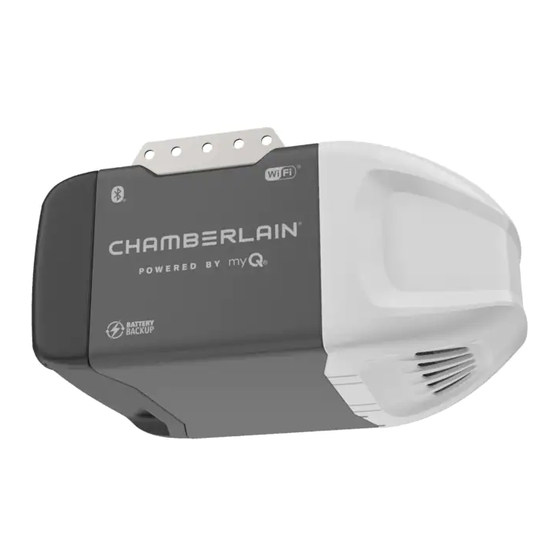
Smart Garage Opener
• Please read this manual and the enclosed safety materials carefully!
• Fasten the manual near the garage door after installation.
• The door WILL NOT CLOSE unless the Protector System
and properly aligned.
• Periodic checks of the garage door opener are required to ensure
safe operation.
• The model number label is located on the front panel of your garage
door opener.
• This garage door opener is compatible with MyQ® and
is connected
®
Security+ 2.0® accessories.
• DO NOT install on a one-piece door if using devices or features
providing unattended close. Unattended devices and features are
to be used ONLY with sectional doors.
Owner's Manual
C450C
Chain Drive
Garage Door Opener
FOR RESIDENTIAL USE ONLY
PRE-PROGRAMMED REMOTE CONTROL
INCLUDED
TO WATCH VIDEOS GO TO:
tinyurl.com/lgh5x3h
Contents
Preparation ......................................2-5
Assembly .......................................6-10
Installation .................................. 11-28
Install The Door Control ............ 21-22
Install The Protector System® .... 23-26
Connect Power ......................... 27-28
Adjustments ................................. 29-31
MyQ® Smartphone Control .................32
Operation ..................................... 33-37
Using your Garage Door Opener .....34
To Open The Door Manually ...........34
Multi-Function
Control Panel ........................... 35-36
Keyless Entry ................................36
Homelink® ...................................36
To Erase The Memory .....................37
Maintenance .....................................38
Troubleshooting ........................... 39-40
Accessories ........................................41
Warranty ...........................................42
Repair Parts ................................. 43-44
www.chamberlain.com
www.mychamberlain.com
Advertisement
Table of Contents

Subscribe to Our Youtube Channel
Related Manuals for Chamberlain C450C


Summary of Contents for Chamberlain C450C
- Page 1 Owner’s Manual Contents C450C Preparation ........2-5 Assembly ........6-10 Chain Drive Installation ........11-28 Garage Door Opener Install the Door Control .... 21-22 Install the Protector System® ..23-26 FOR RESIDENTIAL USE ONLY Connect Power ......27-28 Adjustments ......... 29-31 PRE-PROGRAMMED REMOTE CONTROL MyQ®...
- Page 2 Torsion Extension Spring Spring...
- Page 3 • Move your router closer to the garage door opener to minimize interference from walls and other objects • Buy a Wi-Fi range extender • Buy a Chamberlain MyQ ® Internet Gateway (CIGBUC) see page 41 Visit wifihelp.chamberlain.com for more details...
-
Page 5: Assembly
DOOR CONTROL ASSEMBLY INSTALLATION Bolt Bolt Wing Nut Lag Screw 5/16"-9x1-5/8" (4) 1/4"-20x1-3/4" 1/4"-20 (2) Drywall Anchors (2) Self-Threading Screw Threaded Clevis Pin 5/16"x1-1/2" 1/4"-14x5/8" (2) Shaft Clevis Pin 5/16"x1" Clevis Pin 5/16"x1-1/4" Master Link (2) Screw 6-32x1" (2) Lock Nut 1/4"-20 Carriage Bolt 1/4"-20x1/2"... - Page 6 Slide to stops on top and sides of “U” bracket Screwdriver “U” Bracket (TO MOTOR UNIT) Rail Tab On Top Trolley Wear Pads Front Rail Section (TO DOOR)
- Page 7 HARDWARE Lock Nut Bolt 1/4"-20x1-3/4" 1/4"-20 Hex Screws Bolts (Mounted in the 8-32x7/16 garage door opener) Chain Spreader “U” Bracket Bolt Cover Protection Bolt Hole Lock Nut...
- Page 8 HARDWARE Nut 3/8" Lock Washer 3/8" Bolt Rail Tab Chain/cable Rail Bolt Grease Inside Pulley Idler Pulley Lock Washer...
- Page 9 HARDWARE Master Link Threaded Shaft Sprocket Figure 2 Figure 1 Figure 3 Master Link Inner Nut Lock Washer Threaded Master Shaft Link Outer Nut...
- Page 10 Trolley To Tighten Outer Lock Threaded Outer Nut Washer Shaft To Tighten Inner Nut Inner Nut Chain 1/4" (6 mm) Base of Rail Mid length of Rail...
- Page 12 OPTIONAL CEILING MOUNT Header Wall FOR HEADER BRACKET Vertical Centerline of Garage Door Structural Supports Unfinished Ceiling Level (Optional) Sectional door with curved track One-piece door with horizontal track Header Wall Header Wall 2" (5 cm) 2" (5 cm) Track Door Track Highest...
-
Page 13: Installation
WALL INSTALLATION Header Wall Vertical Centerline of Structural Wall Mounting Garage Door Holes Support HARDWARE Header Bracket Lag Screw 5/16"-9x1-5/8" Horizontal Screw Line Door Spring Highest Point Optional Mounting of Garage Holes Door Travel Garage Door CEILING INSTALLATION Header Bracket Finished Ceiling 6"... - Page 14 HARDWARE Clevis Pin Ring Fastener 5/16"x1-1/2" Ring Fastener Clevis Pin Connected Disconnected One-piece door All other without tracks door types...
- Page 15 HARDWARE Lag Screw 5/16"-18 5/16"-9x1-5/8" Lock Washer Hex Bolt 5/16"-18 5/16"- 18x7/8" EXAMPLES Finished Ceiling Unfinished Ceiling Not Provided Finished Ceiling Not Provided Lag Screw Lag Screw Hex Bolt Lock Washer Provided...
- Page 17 HARDWARE Self-Threading Screw 1/4"-14x5/8" Horizontal Reinforcement Vertical Reinforcement FIGURE 1 FIGURE 2 Vertical Reinforcement Vertical Reinforcement Vertical Centerline Vertical of Garage Door Centerline Door Bracket of Garage Door Hardware Door Bracket (not provided) Self-Threading Screw FIGURE 3 FIGURE 4 Inside Edge of Door or Reinforcement Board Vertical Hardware...
- Page 18 Header Wall 2x4 Support (Finished Ceiling) Header Bracket Door Bracket Optional For a door with no exposed Placement framing, or for the optional of Door installation, use lag screws Bracket 5/16"x1-1/2" (not provided) to fasten the door bracket. Vertical HARDWARE Centerline of Garage Door...
- Page 19 HARDWARE Clevis Pin 5/16"x1-1/4" Clevis Pin 5/16"x1" Hex Bolt 5/16"-18x7/8" Lock Washer Ring Fastener 5/16" -18 Nut 5/16"-18 Ring Fastener Clevis Pin 5/16"x1" Lock Washer Hex Bolt Straight Door Arm (Groove Clevis Pin facing out) 5/16"x1-1/4" Curved Door Arm...
- Page 20 Straight Door Arm (Groove facing out) Curved Door Arm One-Piece Door without Track HARDWARE Ring Fastener Ring Fastener Lock Washer Clevis Pin Clevis Pin 5/16"x1-1/4" Clevis Pin 5/16"x1" Hex Bolt 5/16"-18x7/8" 5/16"x1" Lock Washer Ring Fastener Clevis Pin 5/16"x1-1/4" 5/16" -18 Nut 5/16"-18 Hex Bolts One-Piece Door with Track...
- Page 21 Wall 7/16" (11 mm) DRYWALL GANG BOX Drywall Anchor 6-32x1" 6ABx1" HARDWARE DRYWALL GANG BOX Screw Screw 6ABx1" (2) 6-32x1" (2) 6-32x1" Drywall Anchor Drywall Anchors (2) 6ABx1"...
- Page 22 HARDWARE Insulated Staple (Not Shown) 7/16" (11 mm) Staple...
- Page 23 HARDWARE Wing Nut Carriage Bolt 1/4"-20 1/4"-20 x 1/2" No more than 6 inches (15 cm) Safety Reversing Sensor Invisible Light Beam 6" (15 cm) max. above floor Carriage Bolt Protection Area Wing Nut Facing the door from inside the garage...
- Page 24 (Not provided) (Not provided) (Not provided) No more than 6 inches (15 cm) Wing Nut Carriage Bolt Wing Nut Lens Carriage Bolt...
- Page 25 HARDWARE Insulated Staple (Not Shown) Staple 7/16" (11 mm)
- Page 26 Pre-installed 7/16" (11 mm) wires Safety reversing sensor wires Wire nuts (not provided) Safety reversing sensor wires Pre-installed wires Yellow (for example) White Purple (for example) White/Black Yellow Purple Yellow Purple 7/16" (11 mm) To insert or remove the wires from the terminal, push in the tab with a screwdriver tip.
- Page 27 Ground Tab Black Wire Green Ground Screw Ground Wire White Wire...
- Page 28 Wing Nut (invisible light beam) Amber LED Green LED SENDING SENSOR RECEIVING SENSOR If the receiving sensor is in direct sunlight, switch it with sending sensor so it is on the opposite side of the door.
-
Page 29: Adjustments
Correct Incorrect UP Button Adjustment Button DOWN Button PROGRAMMING BUTTONS DOWN (Close) UP (Open) - Page 30 UP Button Adjustment Button DOWN Button PROGRAMMING BUTTONS...
- Page 32 Google Play Blue LED App Store...
-
Page 35: Operation
Operation To turn the Light feature on or off (Factory default is On): Multi-Function Control Panel Turn OFF: SYNCHRONIZE THE DOOR CONTROL: To synchronize the door control to the garage door opener, press the Close the garage door. push bar until the garage door opener activates (it may take up to 3 presses). Test the door control by pressing the Start with the garage door opener lights "OFF". - Page 36 The command LED The command LED will will flash once. flash once again.
- Page 37 LEARN Button Black Adjustment Button...
- Page 41 953EVC Remote Control: Extension: (Optional) For safety For use outside of the home Works with ALL Chamberlain To allow an 8 foot (2.4 m) reversing sensor installation to enable access to the garage openers from 1993-present. door to open fully.
- Page 42 CHAMBERLAIN ® LIMITED WARRANTY The Chamberlain Group, Inc. ® (“Seller”) warrants to the fi rst retail purchaser of this product, for the residence in which this product is originally installed, that it is free from defects in materials and/or workmanship for a STOP! specifi...
-
Page 43: Repair Parts
Repair Parts Rail Assembly Parts Installation Parts Description Part Number Description Part Number Curved Door Arm 041B0035B Chain and Cable 041A5807 Door Bracket with Clevis Pin and 041A5047-1 Pulley K144C0056 Fastener Master Link 004A1008 Emergency Release Rope and 041A2828 Handle Rail 041A5665 Header Bracket with Clevis Pin... - Page 44 041B4245-1 Terminal Block 041A3150 Not Shown Wire Harness 041A7945 © 2017, The Chamberlain Group, Inc. All Rights Reserved Wi-Fi is a registered trademark of Wi-Fi Alliance The Chamberlain Group, Inc. ® App Store is a service mark of Apple Inc.
-
Page 45: Homelink
Manuel du propriétaire Matiéres C450C Préparation ........2-5 Ouvre-porte de garage Montage ........6-10 à chaîne Installation ........11-28 Pose de la commande de porte.. 21-22 Installation du dispositif POUR RÉSIDENCES SEULEMENT Protector System® ....23-26 Raccordement de TÉLÉCOMMANDE PRÉPROGRAMMÉE l’alimentation ......27-28 INCLUSE Réglages ........ - Page 46 Ressort Ressort torsion traction...
- Page 47 • Rapprocher votre routeur de l’ouvre-porte réduire l’interférence des murs et des autres objets • Achetez un prolongateur de portée WiFi • Achetez une passerelle Internet MyQ ® de Chamberlain (CIGBUC) voir la page 41 Visiter wifihelp.chamberlain.com pour plus de détails 5/32 3/16 5/16 9/16 7/16 7/16...
- Page 49 LE MONTAGE LA POSE LA COMMANDE DE PORTE Écrou à oreilles Boulon Boulon Tire-fond de 1/4 de po-20 (2) 1/4 de po-20 x 1-3/4 de po 5/16 de po-9 x 1-5/8 de po (4) Vis autotaraudeuse Axe de chape de 5/16 de po x 1-1/2 de po 1/4 de po-14 x 5/8 de po (2) Chevilles pour murs secs (2)
- Page 50 Faire coulisser le rail jusqu’aux arrêts sur le dessus et aux côtés Tournevis Support en « U » (VERS TÊTE DE PUISSANCE) Patte de rail sur le dessus Chariot Coussinets d'usure Rail avant (VERS PORTE)
- Page 51 FIXATIONS Contre-écrou 1/4 de po-20 Boulon de 1/4 de po- 20 x 1-3/4 de po Boulons (Monté dans Vis hexagonal de la porte de garage) 8-32 x 7/16 de po Écarteur de chaîne Support en « U » Boulon Trou du boulon de protection du couvercle Contre-écrou...
- Page 52 FIXATIONS Boulons Rondelle-freinde 3/8 de po Écrou de 3/8 de po L’onglet du rail Chaîne/câble Rail Boulon Graisse à l'intérieur de la poulie Poulie Rondelle-freinde Écrou...
- Page 53 FIXATIONS Maillon de raccord Tige filetée Pignon Figure 2 Figure 1 Figure 3 Maillon de raccord Écrou intérieur Rondelle- frein Tige Maillon filetée de raccord Écrou extérieur...
- Page 54 Écrou Rondelle Arbre du extérieur frein chariot Pour visser l'écrou extérieur Pour visser l'écrou intérieur Écrou intérieur Chaîne 6 mm (1/4 de po) Mi-longueur du rail Patin du rail...
- Page 56 MONTAGE DU SUPPORT Linteau Ligne du centre vertical DE LINTEAU AU PLANFOND de la porte de garage EN OPTION Solives Plafond non fini Niveau de menuisier (Facultatif) Porte articulée avec guide courbé Porte rigide avec guide horizontal Linteau Linteau 5 cm (2 po) 5 cm (2 po) Guide Porte...
- Page 57 INSTALLATION AU MUR Linteau Ligne du centre vertical de la 2 x 4 fixé sur porte de garage les poteaux Montage mural FIXATIONS Support Tire-fond de de linteau Tire-fond 5/16 de po-9 x 1-5/8 de po horizontaux Ressort de la porte Point le plus élevé...
- Page 58 FIXATIONS Axe de chape de Anneau d'arrêt 5/16 de po x 1-1/2 de po Anneau d'arrêt Axe de chape Connecté Déconnecté Porte rigide Tous autres sans guides types de porte...
- Page 59 FIXATIONS Écrou de Tire-fond de 5/16 de po-18 5/16 de po- 9 x 1-5/8 de po Boulon hexagonal de Rondelle-frein 5/16 de po-18 x 7/8 de po de 5/16 de po-18 EXEMPLES Plafond fini Plafond non fini Non fournie Plafond fini Non fournie Tire-fond Tire-fond...
- Page 61 FIXATIONS Vis autotaraudeuse 1/4 de po-14 x 5/8 de po Renfort horizontal Renfort verticaux FIGURE 1 FIGURE 2 Renforts verticaux Renforts verticaux Ligne du centre vertical de la Ligne du centre porte de garage vertical de la Support de porte de garage la porte «...
- Page 62 Linteau (Plafond fini) Support 2 x 4 Support de linteau Support de la porte Placement facultatif du Pour une porte sans cadre exposé, support ou pour l’installation facultative, de la porte utiliser des tire-fonds de 5/16 de po x 1-1/2 de po (non fournis) pour fixer le support de la porte.
- Page 63 FIXATIONS Axe de chape de 5/16 de po x Axe de chape de 1-1/4 de po 5/16 de po x 1 po Boulon hexagonal de 5/16 de po-18 x 7/8 de po Anneau Rondelle-frein de Écrou de 5/16 d'arrêt 5/16 de po-18 de po-18 Anneau d’arrêt...
- Page 64 Biellette droite (Rainure faisant facea l’oppose) Biellette courbée Porte Rigide Sans Guides Anneau d’arrêt FIXATIONS Anneau d’arrêt Écrou Rondelle-frein Axe de chape 5/16 de po x 1 po Axe de chape de 5/16 de po x Axe de chape de Boulon hexagonal de 1-1/4 de po 5/16 de po x 1 po...
- Page 65 11 mm (7/16 de po) MUR SEC BOÎTE SIMPLE Chevilles à murs secs Vis 6-32 x 1 po Vis 6AB x 1 po FIXATIONS Vis 6-32 x Vis 6AB x MUR SEC BOÎTE 1 po (2) 1 po (2) SIMPLE Chevilles Chevilles à...
- Page 66 FIXATIONS Agrafes isolées (Non illustrés) 11 mm (7/16 de po) Agrafe isolée...
- Page 67 FIXATIONS Boulon à tête bombée Écrou à oreilles et collet carré de 1/4 de po-20 1/4 de po-20 x 1/2 de po Ne sont pas à plus de 15 cm (6 po) Boulon à tête Zone de protection Détecteur inverseur de bombée et sécurité...
- Page 68 (Non fournis) (Non fournis) (Non fournis) À pas plus de 15 cm (6 po) Écrou à oreilles Boulon à tête bombée et collet carré Écrou à oreilles Diffuseur Boulon à tête bombée et collet carré...
- Page 69 FIXATIONS Agrafes isolées (Non illustrés) Agrafe 11 mm (7/16 de po)
- Page 70 Câbles 11 mm préinstallés (7/16 de po) Câbles du capteur de l’inverseur de sécurité Capuchons de connexion (Non fournis) Câbles préinstallés Câbles du capteur de l’inverseur de sécurité Jaune (par exemple) Blanc Violet (par exemple) Blanc / Noir Jaune Violet Jaune Violet 11 mm...
- Page 71 Patte de terre Vis vertede terre Fil noir Fil de terre Fil blanc...
- Page 72 Écrou à oreilles (faisceau de lumiére invisible) Ambre DEL Verte DEL DÉTECTEUR ÉMETTEUR DÉTECTEUR RÉCEPTEUR Si détecteur récepteur est á lalumiére du soleil direct, commutez-la avec détecteur émetteur ainsi il est du bord opposé de la porte.
- Page 73 Mauvais Bouton « UP » Bouton de réglage Bouton « DOWN » BOUTONS DE PROGRAMMATION fermeture « DOWN » d’ouverture « UP »...
- Page 74 Bouton « UP » Bouton de réglage Bouton « DOWN » BOUTONS DE PROGRAMMATION...
- Page 76 Google Play LED bleu App Store...
- Page 79 DEL Commande Barre de poussée Bouton « LEARN » (apprentissage) Bouton « LOCK » Bouton « LIGHT » (verrouillage) (éclairage)
- Page 80 La DEL de commande La DEL de commande clignot une seule fois. clignote à nouveau une seule fois.
- Page 81 Bouton « LEARN » Bouton de réglage noir...
- Page 85 Fonctionne avec TOUS les ouvre- ((Facultatif) Pour la pose du Pour permettre à une porte de la maison vous permettant porte Chamberlain fabriqués capteur de l’inverseur de sécurité de 2,4 m (8 pieds) de s’ouvrir d’activer l’accès au garage à...
- Page 86 GARANTIE LIMITÉE CHAMBERLAIN The Chamberlain Group Inc. (« le Vendeur ») garantit à l’acheteur au détail initial de ce produit pour la résidence dans laquelle ce produit est originalement installé, que ce dernier est exempt de tout défaut matériel ou de fabrication pour une période de temps précisée ci- ARRÊTER!
- Page 87 Pièces de réparation Pièces d’assemblage du rail Pièces pour la pose Description Numéro de Description Numéro de la pièce la pièce Biellette courbée 041B0035B Chaîne et câble 041A5807 Support de porte avec axe 041A5047-1 Poulie K144C0056 de chape et fi xation Maillon principal 004A1008 Poignée et corde de...
- Page 88 041B4245-1 Cordon électrique 041A3150 Bornier à vis Non illustrés 041A7945 Faisceau de câblage © 2017, The Chamberlain Group, Inc. Tous droits réservés The Chamberlain Group, Inc. Wi-Fi ® est une marque déposée de Wi-Fi Alliance 300 Windsor Drive App Store est une marque de service d’Apple Inc.
Need help?
Do you have a question about the C450C and is the answer not in the manual?
Questions and answers
I cant unlock the multifunction control panel. Tried to push lock button and hold for two seconds but does not respond. Light still flashes