Table of Contents
Advertisement
Quick Links
INSTRUCTION MANUAL
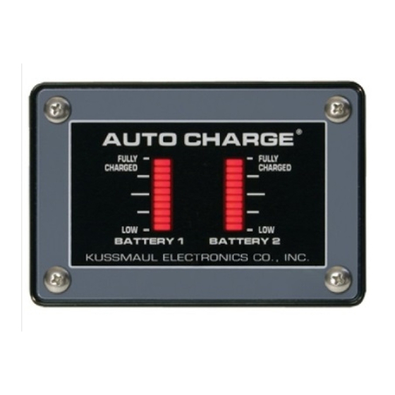
AUTO CHARGE
2000
AUTOMATIC BATTERY CHARGER
INPUT :115 volt, 50/60 Hz, 3.5 amps
3 YEAR WARRANTY
KUSSMAUL ELECTRONICS CO., INC
170 CHERRY AVE., WEST SAYVILLE, N.Y. 11796
TEL: in NY 631-567-0314
MODEL #091-39-12
NOTE :
This charger is designed for
vehicles with dual batteries
and negative ground.
OUTPUT: 18 AMPERES
TOLL FREE: 800-346-0857
BOOK# 091-39-2
REV C: 2-07-03
.
FAX: 631-567-5826
Advertisement
Table of Contents

Related Manuals for KUSSMAUL 091-39


Summary of Contents for KUSSMAUL 091-39
- Page 1 INPUT :115 volt, 50/60 Hz, 3.5 amps OUTPUT: 18 AMPERES 3 YEAR WARRANTY KUSSMAUL ELECTRONICS CO., INC 170 CHERRY AVE., WEST SAYVILLE, N.Y. 11796 TEL: in NY 631-567-0314 TOLL FREE: 800-346-0857 FAX: 631-567-5826...
- Page 2 INTRODUCTION The AUTO CHARGE 2000 is a compact, completely automatic, dual channel battery charger designed for vehicles with two batteries. The charger is rugge- dized to withstand the shock and vibration encountered by vehicle mounted equipment. The battery charger features: •...
- Page 3 Battery Saver & Indicator A 3 ampere BATTERY SAVER is built into the charger. When connected as shown in the installation wiring diagram, loads on battery #1 such as radios and rechargeable hand lights are automatically switched to the BATTERY SAVER when power is applied to the charger.
-
Page 4: Installation Wiring Diagram
Installation Wiring Diagram AUTO CHARGE 2000 Battery Saver Loads (3 amps max.). When the charger is disconnect from 120 volts AC the Battery Saver loads automati- cally are connected to battery #1. CAUTION BATTERY SAVER This battery saver output is a full wave rectified sine wave. The 12.5 volts D.C. has a peak value of approximately 17.5 volts. - Page 5 Specifications: Input: 120 volt, 50/60 Hz, 3.5 amperes Input Fuse: 6 ampere, fast acting Output: 12 volts D.C. 15 amperes Max., total both outputs Remote Sensing: Electronic, sense wires not required Number of Charger Outputs: 2 Number of Battery Saver Outputs: 1 Battery Saver Output: 12 volts D.C., 3 amperes Max.
- Page 6 Kussmaul Electronics Company, Inc. shall have no liability for dam- ages of any kind to associated equipment arising from the installation and /or use of the Kussmaul Electronics Company, Inc. products. The pur- chaser, by the acceptance of the equipment, assumes all liability for any...
- Page 7 INDICATOR INSTALLATION 1. Locate Indicator in a convenient place on the vehicle. 2. Place the template in position and center punch in 3 places. 3. Drill holes as shown. 5. Connect wiring to charger using butt connector supplied. 6. Install as shown. 7.
- Page 8 INDICATOR INSTALLATION 1. Locate Indicator in a convenient place on the vehicle. 2. Place the template in position and center punch in 4 places. 3. Drill holes as shown. 5. Cut out square hole. 6. Connect wiring to charger using butt connector supplied. 7.
Need help?
Do you have a question about the 091-39 and is the answer not in the manual?
Questions and answers