
Related Manuals for GRAUPNER ULTRA DUO PLUS 60


Summary of Contents for GRAUPNER ULTRA DUO PLUS 60
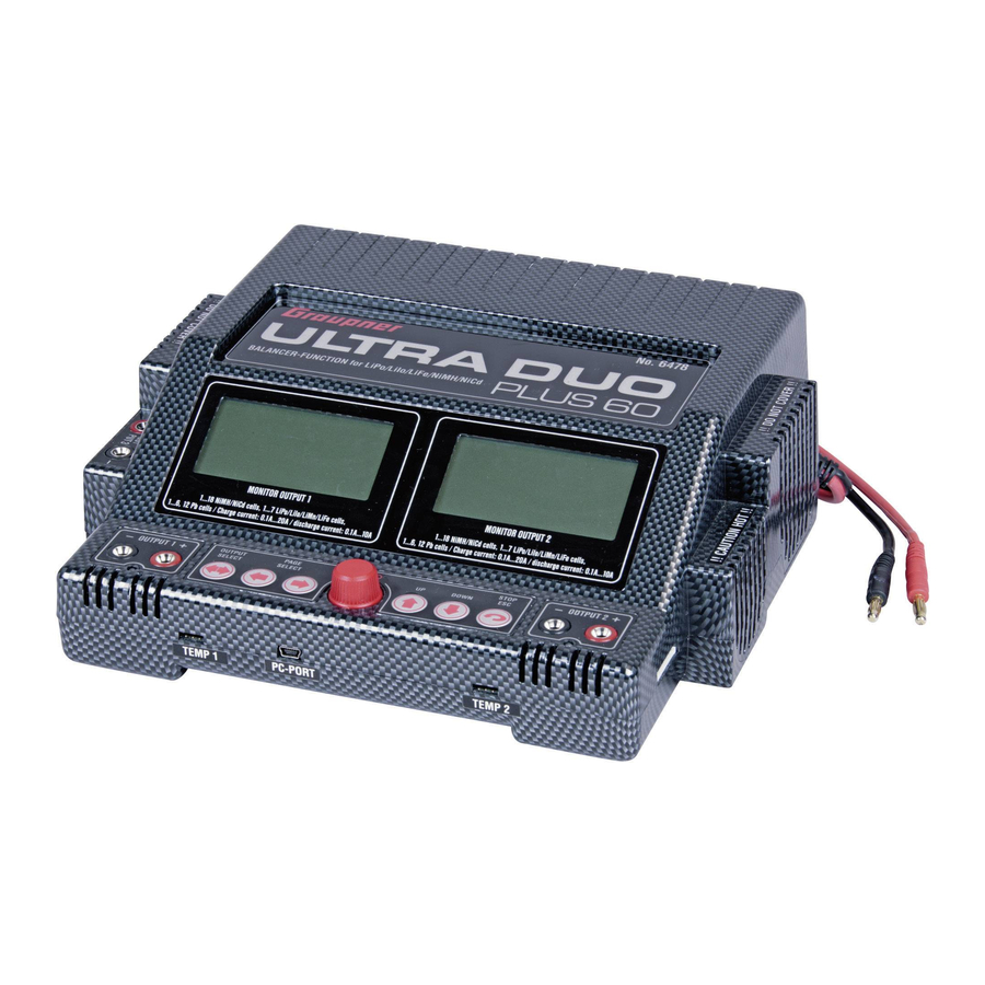
- Page 1 Operating Manual ULTRA DUO PLUS 60 Order-No. 6478 No liability for printing errors. Modifications reserved. 1/55 PAGE...
-
Page 2: Table Of Contents
PN.OF-01 Contents Page Introduction Warnings and safety notes General notes on using the charger Recommended charge leads/polarity Charger controls /connections Using the charger for the first time Cleaning and maintenance Notes and handling of rechargeable batteries PC-Interface Features Main menu flow Control key select flow Memory and battery setup menu screen Charge setup menu flow... -
Page 3: Introduction
A-1. INTRODUCTION Please study these instructions, reading them completely and attentively, before using the unit for the first time. This will guarantee that you will be able to exploit all the facilities of your new battery charger. The warnings and safety notes are particularly important. Please store these instructions in a safe place, and be sure to pass them on to the new owner if you ever dispose of the charger. -
Page 4: Warnings And Safety Notes
A-2. WARNINGS AND SAFETY NOTES • The software does not take the output current of Output 3 into account when it calculates the charge power. This means that the charger will re-boot if the internal mains PSU is overloaded. If devices with a relatively high current drain (more than 1 A) - such as Peltier coolers or heating covers - are connected to the unit, we therefore recommend that you use only one of the two charge outputs, and set the power distribution to 50% / 50%, in order to prevent overloading the internal PSU. -
Page 5: General Notes On Using The Charger
- Non-rechargeable batteries (dry cells). Caution: explosion hazard! - Batteries which are not expressly stated by the manufacturer to be suitable for the currents which this unit delivers during the charge process. - Packs which are already fully charged or hot, or only partially discharged. - Batteries or cells fitted with an integral charge circuit or charge termination circuit. - Page 6 • Connect the battery to be charged to the charger output sockets using a suitable charge lead (red = positive terminal, black = negative terminal). • Be sure to read the information provided by the battery manufacturer regarding charging methods, and observe the recommended charge currents and charge times.
-
Page 7: Recommended Charge Leads/Polarity
LIABILITY EXCLUSION As manufacturers, we at GRAUPNER are not in a position to ensure that you observe the correct methods of operation when installing, using and maintaining this charger. For this reason we are obliged to deny all liability for loss, damage or costs which are incurred due to the incompetent or incorrect use and operation of our products, or which are connected with such operation in any way. -
Page 8: Charger Controls /Connections
8 = 25,9V = + cell 7 the used OUTPUT. GRAUPNER- BALANCER CONNECTOR TYPE EHR-8 A-6. USING THE CHARGER FOR THE FIRST TIME Connect the charger INPUT 12V DC to a 12 V DC car battery min. 50Ah or power supply 5A-40A or the INPUT 100~240V AC to a 100~240V AC mains socket. -
Page 9: Cleaning And Maintenance
power. This means that the charger will re-boot if the internal mains PSU is overloaded. If devices with a relatively high current drain (more than 1 A) - such as Peltier coolers or heating covers - are connected to the unit, we therefore recommend that you use only one of the two charge outputs, and set the power distribution to 50% / 50%, in order to prevent overloading the internal PSU. - Page 10 • Lead-acid batteries are not capable of being charged at high currents. Never exceed the maximum charge rate stated by the battery manufacturer. • Protect batteries from vibration, and do not subject them to mechanical stress or shock. • Batteries can generate explosive gas (hydrogen) when on charge and when being discharged, so it is important to provide good ventilation.
- Page 11 The fundamental rule is that Lithium-based batteries may ONLY be Voltage charged using special chargers, and the charge program must be set up correctly in terms of final charge voltage and capacity for the battery type in use. current Charging Time The charge process is fundamentally different to that required for Ni-Cd or Ni-MH batteries, and is termed a constant current / constant voltage method.
-
Page 12: Pc-Interface
We have been working closely with the manufacturer of the software ‘LogView’, in order to provide optimum facilities for evaluating the data generated by our ULTRA DUO PLUS 60 battery charger. With the help of LogView, which we recommend and support, it is possible to visualise and analyse the serial data delivered by these chargers, and if necessary to export the data in a wide variety of forms. - Page 13 Page 13/55...
-
Page 14: Features
(USA / Japan). Two equal-value independent or dependent (CV-link mode) charge outputs Graupner Balancer socket for 2 x 1 ... 7 NiCd / NiMH / LiPo / LiIo / LiFe cells Sixty memories for storing all essential battery parameters ... -
Page 15: Main Menu Flow
0-2. MAIN MENU FLOW Connect the charger main plug to the input 100…240V AC or the 4mm banana plugs to 11…15V DC, see A-6 ULTRA DUO PLUS 60 GRAUPNER #6478 V1.0 USER NAME = - - - - - - - - -... -
Page 16: Control Key Select Flow
0-3. CONTROL KEY SELECT FLOW Two LCD screens, but key control is possible for only one output. The LCD where key control is possible is indicated by LED which flashes or is on. In setting status, if ESC button is pressed, it directly moves to a higher menu. In operating status, if the ESC button is pressed, operating should stop. -
Page 17: Memory And Battery Setup Menu Screen
1. MEMORY AND BATTERY SETUP MENU SCREEN = - - - - - - - - - BATTERY SETUP <1/2> BATT NAME SETUP<2/2> 01] NiMH GP 6N-4600 TYPE NiMH VOLTS _6CL _7.2V ABCDEFGHIJKLMNOPQR CAPACITY _4600mAh STUVWXYZabcdefghijk MEMORY [01] 01/01/2008 lmnopqrstuvwxyz0123 456789 -.,'#_+/ ä... - Page 18 1. MEMORY AND BATTERY SETUP MENU SCREEN 1-1. Memory selection - Pressing the dial in Memory[00] then rotate the dial to select the wanted memory. - Memory 0, 1-60 can be selected. In any outputs, 0, 1-60 Memory can be selected and copied, but memory room which is selected by counter output can not be selected.
-
Page 19: Charge Setup Menu Flow
2. CHARGE SETUP MENU FLOW NiMH CHARGE SETUP - = - - - - - - - - CHARGE SETUP <1/2> CHARGE SETUP <2/2> CHG CURRENT _4.6A MAX CAPACITY 125% PEAK SENS _5mV/C SAFETY TIMER _75min PEAK DELAY _3min FLAT CHECK _OFF CHARGE TRICKLE... - Page 20 (NiMH/NiCd) batteries can cause explosion and fire! 2-1. CHARGE CURRENT Set charge currents. Follow the instruction of the battery. Graupner batteries should be charged with 0.5-1C (f. e. 6N-4200 should be charged with 4.2A). Transmitter batteries must be charge with less then 2A. Follow the instruction of the transmitter battery and transmitter.
- Page 21 2-7. SAFETY TIMER - If charging is not finished within charging time, this Safety Timer should stop charging. - When charge current is changed, the Safety Timer is also automatically changed. Safety Timer per battery type is gained based on Linear charge mode NiCd, NiMH = (Selected capacity * 60 / Selected current) * 1.5 LiIo, LiPo, LiFe, Pb = (Selected capacity * 60 / Selected current) * 2.0 Safety Timer should be “OFF”...
-
Page 22: Discharge Setup Screen
3. DISCHARGE MENU SCREEN - - = - - - - - - - DISCHARGE SETUP<1/1> DCHG CURRENT _0.0A DCHG CUTOFF _0.0V/C CUT-TEMP. __0°C DISCHARGE MAX CAPACITY __0% MATCHED VOLT _0.00V D:00.0A 1.0V/CL 00°C ... 4x DISCHARGE SETUP<1/1> DCHG CURRENT _0.0A DCHG CUTOFF _0.0V/C CUT-TEMP. - Page 23 - This function is likely to be used more to prevent battery pack from being overheating rather than normal charge completion 3-4. MAX CAPACITY - This is to set your wanted discharge percentage against the selected battery capacity. - If “OFF” is set, this max capacity function is not activated. - If battery capacity is 3000mAh and if you set 10% out of the total max capacity, the charger should stop discharging at 300mAh 3-5.
-
Page 24: Cycle Menu Screen
4. CYCLE MENU SCREEN - - - = - - - - - - CYCLE SETUP <1/1> DIRECTION D:C>D CYCLE TIME AF-CHG DELAY _0min CYCLE AF-DCH DELAY _0min D:C>D 1T C00/D00min CYCLE SETUP <1/1> DIRECTION D:C>D CYCLE TIME AF-CHG DELAY _0min AF-DCH DELAY _0min... -
Page 25: Step Charge Menu Screen
5. STEP CHARGE MENU SCREEN - - - - = - - - - - STEP CHARGE <1/2> STEP CHARGE <2/2> D: ON d 3mV/C 50°C PEAK SENS _5mV/C CUT-TEMP. _50°C TRICKLE CHG __OFF STEP CHARGE DISCHARGE 1600 3800 4500 IMPULSE CHG 1 2 3 4.0A 8.0A 6.0A 4.0A D: ON d00mV/C... - Page 26 5. STEP CHARGE MENU SCREEN 5-1. STEP CAPACITY - This mode is only for NiMH battery, which are discharge before charging. Never charge full batteries in this mode. Use the temperature sensor for safety reasons. - Set wanted charge capacity in each step. - Step charge should be finished at the fourth step based on the selected capacity in the fourth step.
-
Page 27: Balancer Menü
6. BALANCER MENU SCREEN - - - - - = - - - - BALANCE <1/4> BALANCER <2/4> CELL NO. 1 _0.000V BATT CELLS _0CELL CELL NO. 2 _0.000V PACK VOLTS _0.000V CELL NO. 3 _0.000V AVG VOLTS _0.000V CELL NO. 4 _0.000V BALANCE GAP VOLTS... - Page 28 6. BALANCER MENU SCREEN 6-1. BALANCE <1/4> SCREEN - This is to show each cell information which is connected to the balancing port of the charger. BATTCELLS 0CELL - Connected cell number. PACK VOLTS 0.000V – Overall cell voltage AVG VOLTS 0.000V –...
-
Page 29: Data View Screen
7. DATA VIEW SCREEN - - - - - - = - - - DATA VIEW <1/4> CYCLE DATA _0<2/4> INPUT _0.000V FIN.00/00/07 **--:-- OUTPUT _0.000V CHG CAP ____0mAh TEMPERATURE __0.°C PEAK VOLTS _0.000V HIGH TEMP __0.0°C CHG RESITANCE _0.0m DATA VIEW RESISTANCE _0.0m... - Page 30 7. DATA VIEW SCREEN 7-1. DATA VIEW <1/4> - This is to display charge status. INPUT 0.000V -Input Voltage OUTPUT 0.000V -Output Voltage TEMPERATURE 0.0`F -Temp of the temp sensor HIGH TEMP 0.0`F -Max temp of the temp sensor RESISTANCE 0.0m -Battery internal resistance...
- Page 31 7-3. TRACE DATA <3/4> - This is to check battery condition. - Memory consists of “ROM”, even if power is OFF, the data still leaves. - MEMORY setting MIN. RES. 0. 0 - min. internal battery resistance up to now. LAST CHG 0mAh - Last charged capacity...
-
Page 32: Tyre, Battery Heater / Battery Heater Screen / Power Supply
8. TYRE HEATER / BATTERY HEATER SCREEN AND POWER SUPPLY SCREEN - - - - - - - = - - HEATER <1/1> POWER SUPPLY <2/2> VOLTAGE LIMIT 12.0V SET TIME 1 __0min CURRENT LIMIT 5.0A SET TEMP 1 __0°C TIME DELAY __0min POWER &... - Page 33 8. TYRE HEATER / BATTERY HEATER SCREEN AND POWER SUPPLY SCREEN 8-1. How to use Using tyre warmer of GM-Racing #94711 or Much More or battery heater of Much More. Never heat tyres over 80°C and never heat batteries over 50°C. Insert the temp sensor into the tire warmer.
-
Page 34: Motor Run-In Screen
9. MOTOR RUN-IN SCREEN (Warning: only use DC brushed motors or DC fans!) - - - - - - - - = - MOTOR RUN MOTOR BREAK-IN <1/3> Program Mode <2/3> MOTOR Test <3/3> 1st 2nd 3rd 4th Test voltage 0.0V SET VOLT _0.0V... - Page 35 The motor function can only be started, if the other output is not in use! For racing brushed motors and using the internal power supply, we recommend to use a 1-2 Ohm resistor in series of the motor to reduce the max. current flow.
-
Page 36: Config Setup Screen
MOVE FINISH MELODY LCD CONTRAST 00/00/2000 am00:00:00 DISPLAY LAST CONFIG SETUP <2/4> TIME SETUP <3/4> USER NAME <4/4> 01] GRAUPNER GmbH TEMP SCALE °C SET DATE 17/05/2007 BUTTON SOUND __ON SET TIME am11:20 ABCDEFGHIJKLMNOPQR LANGUAGES _ENGLISH SET TIME FORMAT 12h... - Page 37 10. CONFIG SETUP SCREEN 10-1. CONFIG SETUP <1/4> and <2/4> - TEMP SCALE Can be set to either “C” or “F” - BOTTON SOUND Button can be set to ON or OFF Even if the button sound is OFF, the charger should beep when error occurs. - FINISH SOUND ...
-
Page 38: Start Select Menu Screen
11. START SELECT MENU SCREEN - = - - - - - - - - - - = - - - - - - - - - - - = - - - - - - - - = - - - - - - CHARGE DISCHARGE STEP CHARGE... - Page 39 - - - - - = - - - - - - - - - - - = - - - - - - - - - - = - BALANCER POWER & HEATER MOTOR RUN 0CL 0.00Vpk 0.00Va __0m __0°C __0m __0°C BALANCE START POWER &...
- Page 40 11. START SELECT MENU SCREEN 11-1. CHARGE START - CHARGE FLOW a. Pressing the dial moves to the Start mode from Charge screen. b. Select charge process. c. Under RESEVE TIMER “OFF”, press the dial in Reserve charge screen. d. Check battery and cell connection. e.
- Page 41 This is only for NiCD/NiMH battery. Charging has to be NOT “OFF” during charging, this charge has to be continued. This charge mode is very sensitive to charge cable connection, so if connected cable is touched, charging could be finished. Since delta peak is detected every second, it is possible to check delta peak accurately.
- Page 42 j. FAST-CHG This is only for Lilo/LiPo/LiFe battery: CC to CV method. (CC = constant current, CV = constant voltage) Charge finished at 20% of the adjusted charge current. Connect the balancer wires for safety reasons. k. CV-LINK This is only for Lilo/LiPo/LiFe. Same capacity batteries should be used in this mode.
- Page 43 11-2. DISCHARGE START - DISCHARGE PROCESS a. AUTOMATIC Discharging calculating battery cell and discharge current automatically. The charger calculates battery internal resistance and discharge currents every specific time. CUTOFF VOLTAGE: NiCd=0.9V/cell NiMh=1.0V/cell LiIo/Po=3.0V/cell LiFe=2.5V/cell Pb=1.8V/cell Calculating and finish discharging based on above. Cut-TEMP which is used in charging is used.
- Page 44 11-4. MOTOR START - PROCESS SELECT Select process to be operated. BREAK-IN, PROGRAM, TEST - Operation limitation Motor operation could be only possible, if only one channel is used. Second output can not be used at the same time. 11-5. DELAY TIME - This mode is to delay time before CHARGE, DISCHARGE, STEP-CHG This mode is only available for above modes.
-
Page 45: Battery Select Menu Screen
12. BATTERY SELECT MENU SCREEN With connected balancer Balancer connector not connected in connector in LiPo/LiIo/LiFe LiPo/LiIo/LiFe-Mode CC/CV- or automatic mode *CONNECTED CHECK* *SELECT CELLS* [0] cells are now Select [0] cells ** BALANCER ** Connected at the to be charged or ** CONNECTION ** Balancing port discharged. -
Page 46: Operation Menu Screen
13. OPERATION MENU SCREEN (LED ON) Charge, Discharge: [ NORMAL ] CHARGE [ NORMAL ] CHARGE TRACE DATA <3/4> MIN. RES. __0.0m TIME _0:00:00 EXP.FINSH am11:12 LAST CHG ____0mAh CAPACITY _____0mAh FINISH TIME **--:-- LAST DCHG ____0mAh VOLTAGE _0.000V CLOCK am10:00:01 MAX CHG ____0mAh... - Page 47 D:C>D C>D D>C [ NORMAL ] DISCHARGE [ NORMAL ] CHARGE [ NORMAL ] DISCHARGE CYCLE D:C>D 0/10 CYCLE C>D 1/10 CYCLE D>C 1/10 TIME _0:00:00 TIME _0:00:00 TIME _0:00:00 CAPACITY _____0mAh CAPACITY _____0mAh CAPACITY _____0mAh VOLTAGE _0.000V VOLTAGE _0.000V VOLTAGE _0.000V CURRENT...
- Page 48 [PRE-DCHG] DISCHARGE [ NORMAL ] CHARGE TIME _0:00:00 TIME _0:00:00 CAPACITY _____0mAh CAPACITY _____0mAh VOLTAGE _0.000V VOLTAGE _0.000V CURRENT -_0.00A CURRENT +_0.00A RESISTANCE __0.0m RESISTANCE __0.0m BATT TEMP __0.0°C BATT TEMP __0.0°C [DCHG>STEP] DELAY [ TIMER ] DELAY [ NORMAL ] CHARGE END:DELTA-PEAK TIME _0:00:00...
- Page 49 Balance: BALANCE 0N=0.000V BALANCE <1/4> BALANCE <2/4> CELL NO. 1 _0.000V BATT CELLS _0CELL CELL NO. 2 _0.000V PACK VOLTS _0.000V CELL NO. 3 _0.000V AVG VOLTS _0.000V CELL NO. 4 _0.000V GAP VOLTS _0.000V CELL NO. 5 _0.000V MAX NO. 0 _0.000V CELL NO.
- Page 50 13. OPERATION MENU SCREEN 13-1. CHARGE, DISCHARGE OPERATION SCREEN a. OPERATION SCREEN < DISPLAY 1 > - This is shown during CHARGE, DISCHARGE, STEP-CHARGE, CYCLE operating. (Operation Time, capacity, voltage, current, resistance, batt. Temp.) - Selected current can be changed during operating. Current can be changed in NORMAL, LINEAR, REFLEX, CC/CV, CV-LINK charge modes.
- Page 51 ex1) INTERNAL POWER LIMITE = 360W Using DC POWER 15V / 20A (300W) If power rate is set to 50%, CH1=150W, CH2=150W can be used in accordance with internal wattage limitation. ex2) INTERNAL POWER LIMITE = 360W AC INTERNAL POWER (120W) If power rate is set to 50%, CH1=60W, CH2=60W can be used in accordance with AC power wattage limitation.
-
Page 52: Error Message Screen
14. ERROR MESSAGE SCREEN The error will be displayed on the LCDisplay. INPUT VOLTAGE NO BATTERY [ REVERSE POLARITY ] * The present input * A battery is not * A battery is voltage is _0.00V. connected to the connected to the * Please check the output output in reverse ! -
Page 53: Specification
15. SPECIFICATION Battery: Charge currents / power 100 mA to 20.0 A / max. 120W overall with internal power supply 100 mA to 20.0 A / max. 2x 180 W for using both outputs or 1x 250W for using just one output with external 11...15V DC power supply Discharge currents / power 100 mA to 10 A / max. -
Page 54: Environnemental Protection Notes
EU Conformity Declaration We hereby declare that the following product: ULTRA DUO PLUS 60; Order-No. 6478 conforms with the essential protective requirements as laid down in the directive for harmonising the statutory directives of the member states concerning electro-magnetic interference (89/336/EWG) and LVD (73/23/EG). -
Page 55: Warranty
If material defects or manufacturing faults should arise in a product distributed by us in the Federal Republic of Germany and purchased by a consumer (§ 13 BGB), we, Graupner GmbH & Co. KG, D-73230 Kirchheim/Teck, Germany, acknowledge the obligation to correct those defects within the limitations described below.