Advertisement
Advertisement
Table of Contents

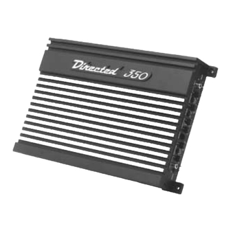
Summary of Contents for Directed Audio Model 350 Power Amplifier
- Page 1 OWNER’S MANUAL Model 350...
- Page 2 DEI dealer. Amplifiers not installed by an authorized Directed dealer are covered by a one year parts- and-labor limited warranty. Please save your sales receipt and refer to the warranty section of this manual for complete details. © 2000 Directed Electronics, Inc.
-
Page 3: Table Of Contents
© 2000 Directed Electronics, Inc. They may also impair a driver’s ability to hear traffic sounds or emergency vehi- cles. Use common sense and practice safe listening habits when listening to or... -
Page 4: Installation Guidelines
8. This amplifier is designed to drive a speaker load that measures from 2- 4 ohms. Keep in mind that heat is the long-term enemy of automotive electronics and that the lower your speaker load, the more heat © 2000 Directed Electronics, Inc. - Page 5 (surface area is what counts); soldering the terminals after crimping is also recommended. © 2000 Directed Electronics, Inc. 10. Due to the high-frequency MOSFET switching power supply used in all Directed Audio amplifiers, filtering the power cable is not generally required (remember that the amp can’t deliver full output if the power...
-
Page 6: Amplifier Connections
5. SPEAKER OUTPUT TERMINALS - Refer to the speaker wiring diagrams (pg.6) for different wiring options. 6. SUBWOOFER OUTPUT - connect the subwoofer to these terminals. © 2000 Directed Electronics, Inc. -
Page 7: Amplifier Controls
5. SUBWOOFER LOW-PASS CROSSOVER - use the gain and FIGURE 2—AMPLIFIER CONTROLS © 2000 Directed Electronics, Inc. crossover frequency controls to adjust the subwoofer output. 6. BASS EQ - This switch activates an 8dB bass boost circuit. Use as necessary for low frequency enhancement. -
Page 8: Speaker Wiring Diagrams
Three channel operation For bridged three channel operation as shown in this diagram, connect right channel RCAcables to the “FRONT” inputs of the amplifier, and left channel RCA cables to the “REAR” inputs of the amplifier. © 2000 Directed Electronics, Inc. -
Page 9: Crossover Setting And Gain Adjustment
Test discs and analyzers may help with this process, but in the end it's your ears that count - listen to the music ! © 2000 Directed Electronics, Inc. -
Page 10: Specification
50 to 250Hz +8 dB, centered at 40Hz 20K ohms Variable from 150 mV to 8 volt 2 to 8 ohms, stereo 4 to 8 ohms, bridged 2 to 4 ohms 10 to 16 VDC © 2000 Directed Electronics, Inc. -
Page 11: Limited Two-Year Consumer Warranty
ALL WARRANTIES INCLUDING BUT NOT LIMITED TO EXPRESS WARRANTY, IMPLIED WARRANTY, WARRANTY OF MERCHANTABILITY, FITNESS FOR PARTIC- © 2000 Directed Electronics, Inc. ULAR PURPOSE, AND WARRANTY OF NON-INFRINGEMENT OF INTELLECTUAL PROPERTY ARE EXPRESSLY EXCLUDED TO THE MAXIMUM EXTENT ALLOWED BY... - Page 12 • POWER CAPACITORS • GOLD-PLATED POWER DISTRIBUTION AND FUSING BLOCKS • GOLD-PLATED POWER AND SPEAKER TERMINALS Always use a © 2000 Directed Electronics, Inc. • Vista, CA 92083 • All Rights Reserved DEI is a proud member of G45054 1/00...


Need help?
Do you have a question about the Model 350 Power Amplifier and is the answer not in the manual?
Questions and answers