
Related Manuals for Sun Oracle 4540 - Phaser Copystation


Summary of Contents for Sun Oracle 4540 - Phaser Copystation
- Page 1 Sun Fire X4500/X4540 Server Service Manual Service Manual Part No. 819-4359-19 May 2010, Revision A...
- Page 2 Graphical User Interface was developed by Sun Microsystems, Inc. for its users and licensees. Sun acknowledges the pioneering efforts of Xerox in researching and developing the concept of visual or graphical user interfaces for the computer industry. Sun holds a non-exclusive license from Xerox to the Xerox Graphical User Interface, which license also covers Sun’s licensees who implement OPEN LOOK GUIs and otherwise comply with Sun’s written license agreements.
-
Page 3: Table Of Contents
Contents Preface xiii Introduction to the Sun Fire X4500 and X4540 Servers 1–1 Features of the Sun Fire X4500 1–1 1.1.1 System Configurations (X4500) 1–2 1.1.2 Standard I/O (X4500) 1–2 1.1.3 Summary of Features (X4500) 1–3 Features of the Sun Fire X4540 1–4 1.2.1 System Configurations (X4540) 1–4 1.2.2... - Page 4 Accessory Kit (X4540) 1–16 Additional Options and Replaceable Components (X4500) 1–16 Additional Options and Replaceable Components (X4540) 1–18 Powering On and Configuring BIOS Settings 2–1 Powering On the Server 2–2 Powering Off the Server 2–3 Automatic Power-Off Events 2–3 Configuring BIOS Settings 2–4 2.4.1 Changing the Configuration of a BIOS Menu Item...
- Page 5 2.12.2.5 BIOS Advanced Menu, Advanced ACPI Configuration Screen (X4500) 2–19 2.12.2.6 BIOS Advanced Menu, Event Logging Details Screen (X4500) 2–20 2.12.2.7 BIOS Advanced Menu, Hyper Transport Configuration Screen (X4500) 2–21 2.12.2.8 BIOS Advanced Menu, IPMI 2.0 Configuration Screen (X4500) 2–22 2.12.2.9 BIOS Advanced Menu, IPMI 2.0, View BMC Event Log Screen (X4500) 2–23...
- Page 6 2.12.6.1 BIOS Chipset Menu, NorthBridge Configuration Screen (X4500) 2–39 2.12.6.2 BIOS Chipset Menu, NorthBridge Memory Configuration Screen (X4500) 2–40 2.12.6.3 BIOS Chipset Menu, NorthBridge ECC Configuration Screen (X4500) 2–41 2.12.6.4 BIOS Chipset Menu, NorthBridge IOMMU Configuration Screen (X4500) 2–42 2.12.6.5 BIOS Chipset Menu, SouthBridge Configuration Screen (X4500) 2–43 2.12.7 BIOS Exit Options Menu Screen (X4500) 2–44...
- Page 7 2.16.2.10 BIOS Advanced Menu, LAN Configuration (X4540) 2– 2.16.2.11 BIOS Advanced Menu, IPMI 2.0, LAN Configuration Screen (X4540) 2–61 2.16.2.12 BIOS Advanced Menu, MPS Configuration (X4540) 2– 2.16.2.13 BIOS Advanced Menu, PCI Express Configuration (X4540) 2–63 2.16.2.14 BIOS Advanced Menu, Configure Remote Access (X4540) 2–64 2.16.2.15 BIOS Advanced Menu, USB Configuration (X4540) 2–...
- Page 8 2.19 Resetting the SP 2–84 2.20 Updating BIOS 2–84 2.21 BIOS ROM Memory 2–85 2.22 Devices and PCI Slots 2–85 2.23 Disabling OPROM Scanning 2–86 Maintaining the Sun Fire X4500 and X4540 Servers 3–1 Tools and Supplies Needed 3–1 Locations of Components 3–2 FRUs/CRUs and BIOS Compatibility (X4540) 3–4 3.3.1 HyperTransport 3.0 Support 3–4...
- Page 9 ▼ To Replace the Front Indicator Board (FRU) 3-28 ▼ To Replace a Hard Drive (CRU) 3-31 3.9.4 Replacing a Solid-State Drive (Sun Fire X4540 CRU) 3–35 3.9.4.1 SSD Restrictions 3–36 ▼ To Replace an SSD 3-36 3.9.5 Replacing a Power Supply (CRU) 3–40 ▼...
- Page 10 POST Code Checkpoints B–8 C. Status Indicator LEDs C–1 Front Panel LEDs C–2 C.1.1 Rear Panel LEDs C–4 Disk Drive and Fan Tray LEDs C–6 C.2.1 CPU Board LEDs C–10 GRASP Board LED (Sun Fire X4500) C–13 CPU Module Debug LEDs C–15 D.
- Page 11 G. Early-Production Slide Rail and CMA Information G–1 Removing the Cable Management Arm for the X4500 G–1 Removing the Cable Management Arm for the X4500 G–3 H. Device Paths H–1 Sun Fire X4500 Device Paths H–1 Sun Fire X4540 Device Paths H–3 Index Index–1 Contents...
- Page 12 Sun Fire X4500/X4540 Server Service Manual • May 2010...
-
Page 13: Preface
Preface This Sun Fire X4500/X4540 Service Manual contains information and procedures for maintaining and upgrading the server, including the system BIOS. Related Documentation All Sun hardware documentation is available at: http://docs.sun.com/ For the most up-to-date information about the product name, navigate to the product name document collection using the High-End Servers and Blade Servers product category links. - Page 14 Documentation, Support, and Training The Sun web site provides information about the following additional resources: Sun Function Documentation http://www.sun.com/documentation Support http://www.sun.com/support/index.jsp Training http://www.sun.com/training/ Warranty http://www.sun.com/service/support/warranty/index.html Sun Welcomes Your Comments Sun is interested in improving its documentation and welcomes your comments and suggestions.
-
Page 15: Introduction To The Sun Fire X4500 And X4540 Servers
C H A P T E R Introduction to the Sun Fire X4500 and X4540 Servers This chapter contains an overview of the Sun Fire™ X4500 and X4540 servers, including features and orderable components. This chapter contains the following procedures and information: Section 1.1, “Features of the Sun Fire X4500”... -
Page 16: System Configurations (X4500)
1.1.1 System Configurations (X4500) The server provides the following maximum system configurations: 8 DDR-I DIMM slots (4 per processor), up to 2 GB per DIMM (16 GB per system) ■ Up to forty-eight 3.5-inch SATA-I disk drives of 250 to 1 TB capacity each (48 TB ■... -
Page 17: Summary Of Features (X4500)
1.1.3 Summary of Features (X4500) summarizes the features of the Sun Fire X4500 server. TABLE 1-1 Summary of Features (X4500) TABLE 1-1 Feature or Component Sun Fire X4500 Server Two Revision E AMD64 Opteron quad-core processors on two CPU modules. Processor BIOS 8 Mbit Flash memory with LPC interface. -
Page 18: Features Of The Sun Fire X4540
Features of the Sun Fire X4540 The Sun Fire X4540 server is a mid-level, modular, rack-optimized server in the Sun x64 product family; the family platform includes servers engineered for AMD Opteron CPUs and deployment into commercial server markets in a slide-mounted, horizontally biased enclosure for rack cabinet installations, primarily in datacenter locations. -
Page 19: Summary Of Features (X4540)
The servers also provide an Integrated Lights-Out Management (ILOM) service processor function that includes remote boot and remote software upgrades. 1.2.3 Summary of Features (X4540) summarizes the features of the Sun Fire X4540 server. TABLE 1-2 Summary of Features (X4540) TABLE 1-2 Feature or Component... -
Page 20: Exterior Features, Controls, And Indicators
Summary of Features (X4540) TABLE 1-2 Feature or Component Sun Fire X4540 Server PCIe I/O Three low-profile x8 PCIe slots. Other I/O • Four USB 2.0 ports • One VGA video port (D-15 connector on controller) • Compact Flash card slot Power •... -
Page 21: Front Panel
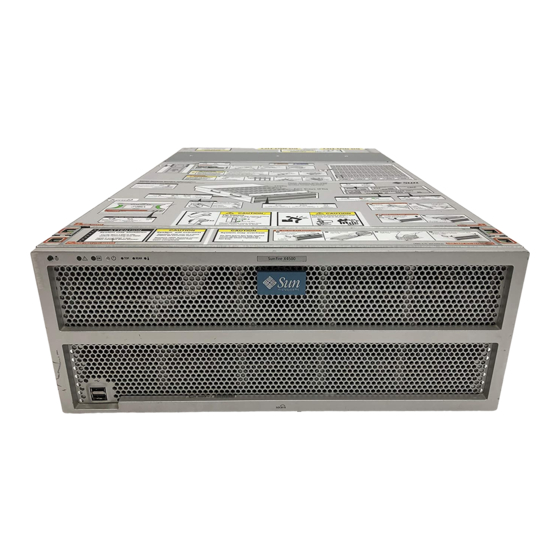
Section 1.3.6, “Component Locations (X4540)” on page 1-14 ■ Section 1.3.7, “Sensor Information” on page 1-15 ■ 1.3.1 Front Panel shows the front panel. FIGURE 1-1 Sun Fire X4500/X4540 Server Front Panel Features FIGURE 1-1 Figure Legend Serial number label Two USB 2.0 connectors Serial number label 1.3.2... -
Page 22: Rear Panel (X4500)
Controls and Indicators FIGURE 1-2 1.3.3 Rear Panel (X4500) Figure Legend Locate button/LED System Fault LED Power/OK LED System power button Top fault LED Rear fault LED System Over Temperature shows the features of the rear panel. lists and describes each FIGURE 1-3 TABLE 1-3 feature. - Page 23 Sun Fire X4500 Rear Panel FIGURE 1-3 11 12 Figure Legend—Sun Fire X4500 Rear Panel Features TABLE 1-3 Name Description Power Supply LED Steady on—Fault. Service action required. (amber) Off—No fault. Power Supply LED (green) Steady on—Power is on (AC/DC are OK). Blinking —Blinks briefly once every 3 seconds.
- Page 24 Figure Legend—Sun Fire X4500 Rear Panel Features TABLE 1-3 Name Description Serial management port SER MGT—RJ45 serial management port (serial connection to service processor). Locate button/LED (white) Toggles on/off locally—Operators can turn on this on remotely to help them locate the enclosure in a crowded server room.
-
Page 25: Rear Panel (X4540)
1.3.4 Rear Panel (X4540) Note – For a quick and concise description of these actions refer to the service label located on the hard drive access cover. shows the features of the rear panel. lists and describes each FIGURE 1-4 TABLE 1-4 feature. - Page 26 Sun Fire X4540 Rear Panel Features TABLE 1-4 Name Description Chassis ground To connect grounding straps. Mounting plate Only for mounting CMA on X4500. PCIe Three slots for X-option cards. Locate button/LED (white) Toggles on/off locally—Operators can turn on this LED remotely to help them locate the server in a crowded server room.
-
Page 27: Component Locations (X4500)
shows the locations of the Sun Fire X4540 server components, with the FIGURE 1-5 covers removed. 1.3.5 Component Locations (X4500) Sun Fire X4500 Component Locations FIGURE 1-5 CMA mounting plate Power supplies (2) System Controller (not visible under power supplies) contains: Power distribution board (not visible -- - CPUs (2) -
Page 28: Component Locations (X4540)
1.3.6 Component Locations (X4540) Sun Fire X4540 Component Locations FIGURE 1-6 Power supplies (2) System Controller (not Power distribution visible under power supplies) contains: board (not visible -- under power supplies) - CPUs (2) - DIMMs (8 per CPU) - Battery - Service Processor - PCIe slots (3) Disk drives (48) -
Page 29: Sensor Information
1.3.7 Sensor Information Information on the location of the server’s sensors can be found in Sun Fire™ X4500/X4540 Servers Diagnostics Guide, 819-4363. For information on sensors that report on hardware conditions, see Sun™ Integrated Lights Out Manager 3.0 Supplement for Sun Fire X4540 Server, 820-5549-10. Accessory Kit (X4500) lists the contents of the accessory kit that is shipped with the Sun Fire TABLE 1-5... -
Page 30: Accessory Kit (X4540)
Accessory Kit (X4540) lists the contents of the accessory kit that is shipped with the Sun Fire TABLE 1-6 X4540 server. Sun Fire X4540 Accessory Kit TABLE 1-6 Item Sun Fire X4540 Getting Started Guide (printed manual) Serial-to-RJ45 cable adapter (DB9S-to-RJ-45F) Important Safety Information for Sun Hardware Systems (printed manual) Software License Agreement (printed manual) Additional Options and Replaceable... - Page 31 Sun Fire X4500 Replaceable Components TABLE 1-7 Component Part Number Power Supply #300-1787, X4502A-Z (X-option) Fan Module (5 Fan Modules/system) #541-0458 Seagate Galaxy 250GB #541-1468 Hitachi Kurafone2 500GB #541-1467 Hitachi GeminiK 500GB #541-3050 Hitachi GeminiK 750GB #540-7244 Hitachi GeminiK 1TB #540-7507 2-GB DIMMs, Pair (2 DIMMs, 4 GB total) Registered #541-1903...
-
Page 32: Additional Options And Replaceable Components (X4540)
Additional Options and Replaceable Components (X4540) lists the after-factory options and replaceable components for the Sun Fire TABLE 1-8 X4540 server. Whether the items are customer-replaceable units (CRUs) or field-replaceable units (FRUs) is indicated in the last column of the table. Supported components and their part numbers are subject to change over time. - Page 33 Sun Fire X4540 Replaceable Components TABLE 1-8 Component Marketing Part Number CRU or FRU 2 DIMMs x 4GB, 1Gb-based, single-rank DIMMs #541-1304 (8 GB total) registered ECC Memory, 16 slots/system X5035 (X-option) 2 DIMMs x 8GB, 2Gb-based, single-rank DIMMs #541-3419 (8 GB total) registered ECC Memory, 16 slots/system X8356A (X-option) System Controller Assembly with I/O controller board...
- Page 34 1-20 Sun Fire X4500/X4540 Server Service Manual • May 2010...
-
Page 35: Powering On And Configuring Bios Settings
C H A P T E R Powering On and Configuring BIOS Settings This chapter contains the following procedures and information. Section 2.1, “Powering On the Server” on page 2-2 ■ Section 2.2, “Powering Off the Server” on page 2-3 ■... -
Page 36: Powering On The Server
Section 2.23, “Disabling OPROM Scanning” on page 2-86 ■ Powering On the Server Before powering on your server for the first time, follow the installation and cabling instructions provided in the Sun Fire X4540 Installation Guide, available online at the URL described in “Related Documentation”... -
Page 37: Powering Off The Server
Top (disk drive or fan fault) Rear (power supply or system controller fault) System over temperature 2. Use a nonconducting stylus to press and release the recessed Power button on the server front panel. See FIGURE 2-1 When main power is applied to the full server, the Power/OK LED next to the Power button lights and remains lit. -
Page 38: Configuring Bios Settings
Configuring BIOS Settings This section describes how to view and modify the BIOS settings. The Basic Input/Output System (BIOS) has a Setup utility stored in the BIOS flash memory. The Setup utility reports system information and can be used to configure the BIOS settings. -
Page 39: Ethernet Port (Nic) Device And Driver Naming
4. Modify the setup field and close the screen. 5. If you need to modify other setup parameters, use the arrow and Tab keys to navigate to the desired screen and menu item, then repeat Steps 1 through 3. Otherwise, go to Step 5. 6. -
Page 40: Nic Naming Conventions
2.5.1 NIC Naming Conventions for a diagram that explains how operating systems and interfaces name FIGURE 2 the four NICs shown in FIGURE 1 Sun Fire X4500 NIC Naming Conventions FIGURE 2 BIOS Solaris 10 Red Hat Linux slot slot e1000 e1000 eth2... -
Page 41: Bios Option Rom Size Limitation
3. Press Enter. The dialog box closes. 4. Press F10 or use the arrow keys to scroll to Exit -> Save Changes and Exit. A dialog asks if you want to save your changes and exit. 5. Press Enter to save your changes and exit the BIOS utility. BIOS Option ROM Size Limitation The BIOS Option ROM is 128 KB. -
Page 42: Bios Setup Screens (X4500)
BIOS Setup Screens (X4500) contains summary descriptions of the seven top-level BIOS setup screens. TABLE 2-1 BIOS Setup Screens Summary (X4500) TABLE 2-1 Screen Description BIOS Main Menu General system information. Screen (X4500) BIOS Advanced Configuration information for the CPUs, IDE, SuperIO, ACPI, Event Menu, Main Screen Log, Hyper Transport, IPMI, MPS, PCI Express, Remote Access, and (X4500) - Page 43 BIOS Utility Menu Tree (X4500) FIGURE 2-2 PCI/PnP Security Advanced Chipset Main menu Boot menu Exit menu menu menu menu menu Boot NorthBridge Configuration Settings Configuration SouthBridge Boot Device Configuration Configuration Priority Super I/O Disk Configuration Drives Advanced Removable ACPI Memory ACPI Drives...
-
Page 44: Device Boot Detection Priority (X4500)
2.10 Device Boot Detection Priority (X4500) shows the devices and PCI slots, and the order that the BIOS detects them. TABLE 2-2 Devices and BIOS Detection Order TABLE 2-2 Order Device Bus Hex Address Marvell 0 Marvell 1 USB 1.1 USB 2 Marvell 2 Marvell 3... -
Page 45: Drives Mapping (X4500)
2.11 Drives Mapping (X4500) The following graphic shows the drives mapping scheme of the system. The boot drives are 0 or 1. (Default boot drive is in slot 0 and the default mirrored drive is in slot 8.) It is required to use one of these drives from which to boot the system. Sun Fire X4500 Drives Map FIGURE 2-3 Chapter 2... -
Page 46: Bios Setup Menu Screens (X4500)
2.12 BIOS Setup Menu Screens (X4500) The following figures show sample BIOS setup menu screens. Section 2.12.1, “BIOS Main Menu Screen (X4500)” on page 2-13 ■ Section 2.12.2, “BIOS Advanced Menu, Main Screen (X4500)” on page 2-14 ■ Section 2.12.3, “BIOS PCI/PnP Menu (X4500)” on page 2-30 ■... -
Page 47: Bios Main Menu Screen (X4500)
2.12.1 BIOS Main Menu Screen (X4500) Main Advanced PCIPnP Boot Security Chipset Exit ******************************************************************************** * System Overview ** Use [ENTER], [TAB] * ***************************************************** or [SHIFT-TAB] to * AMIBIOS ** select a field. * Version : 08.00.10 * Build Date: 04/12/06 ** Use [+] or [-] to * ID : 0ABIG014... -
Page 48: Bios Advanced Menu, Main Screen (X4500)
2.12.2 BIOS Advanced Menu, Main Screen (X4500) Main Advanced PCIPnP Boot Security Chipset Exit ******************************************************************************** * Advanced Settings * Options for CPU * *************************************************** * * WARNING: Setting wrong values in below sections may cause system to malfunction. * * CPU Configuration * * IDE Configuration * * SuperIO Configuration * * ACPI Configuration... - Page 49 2.12.2.1 BIOS Advanced Menu, CPU Configuration Screen (X4500) Advanced ******************************************************************************** * CPU Configuration * This option should * Module Version: 14.09 * remain disabled for * Physical Count: 2 * the normal operation. * Logical Count : 4 * The driver developer * *************************************************** * may enable it for * Dual Core AMD Opteron(tm) Processor 285 * testing purpose.
-
Page 50: Bios Advanced Menu, Ide Configuration Screen (X4500)
2.12.2.2 BIOS Advanced Menu, IDE Configuration Screen (X4500) Advanced ******************************************************************************** * IDE Configuration * DISABLED: disables the * * *************************************************** * integrated IDE * OnBoard PCI IDE Controller [Primary] * Controller. * PRIMARY: enables only * * Primary IDE Master : [Not Detected] * the Primary IDE * * Primary IDE Slave... -
Page 51: Bios Advanced Menu, Superio Chipset Configuration Screen (X4500)
2.12.2.3 BIOS Advanced Menu, SuperIO Chipset Configuration Screen (X4500) Advanced ******************************************************************************** * Configure Smc27X Super IO Chipset * Allows BIOS to Select * *************************************************** * Serial Port1 Base * Serial Port1 Address [3F8/IRQ4] * Addresses. * ** Select Screen * ** Select Item * +- Change Option... -
Page 52: Bios Advanced Menu, Acpi Configuration Screen (X4500)
2.12.2.4 BIOS Advanced Menu, ACPI Configuration Screen (X4500) Advanced ******************************************************************************** * ACPI Settings * Enable / Disable * *************************************************** * ACPI support for * ACPI Aware O/S [Yes] * Operating System. * * Advanced ACPI Configuration * ENABLE: If OS * supports ACPI. -
Page 53: Bios Advanced Menu, Advanced Acpi Configuration Screen (X4500)
2.12.2.5 BIOS Advanced Menu, Advanced ACPI Configuration Screen (X4500) Advanced ******************************************************************************** * Advanced ACPI Configuration * Enable RSDP pointers * *************************************************** * to 64-bit Fixed System * * ACPI 2.0 Features [Yes] * Description Tables. * ACPI APIC support [Enabled] * ACPI SRAT Table [Enabled] * AMI OEMB table... -
Page 54: Bios Advanced Menu, Event Logging Details Screen (X4500)
2.12.2.6 BIOS Advanced Menu, Event Logging Details Screen (X4500) Advanced ******************************************************************************** * Event Logging details * View all unread events * * *************************************************** * on the Event Log. * View Event Log * Mark all events as read * Clear Event Log * ** Select Screen * **... -
Page 55: Bios Advanced Menu, Hyper Transport Configuration Screen (X4500)
2.12.2.7 BIOS Advanced Menu, Hyper Transport Configuration Screen (X4500) Advanced ******************************************************************************** * Hyper Transport Configuration * The HyperTransport * *************************************************** * link will run at this * speed if it is slower * CPU0:CPU1 HT Link Speed [Auto] * than or equal to the * CPU0:CPU1 HT Link Width [Auto] * system clock and the... -
Page 56: Bios Advanced Menu, Ipmi 2.0 Configuration Screen (X4500)
2.12.2.8 BIOS Advanced Menu, IPMI 2.0 Configuration Screen (X4500) Advanced ******************************************************************************** * IPMI 2.0 Configuration * View all events in the * * *************************************************** * BMC Event Log. * Status Of BMC Not Working * It will take a max. of * * * View BMC System Event Log * 15 seconds to read all * * Clear BMC System Event Log... -
Page 57: Bios Advanced Menu, Ipmi 2.0, View Bmc Event Log Screen (X4500)
2.12.2.9 BIOS Advanced Menu, IPMI 2.0, View BMC Event Log Screen (X4500) Advanced ******************************************************************************* * Total Number Of Entries: * Use +/- to traverse * *************************************************** * the event log. * SEL Entry Number: [ 1] * SEL Record ID: 0100 * SEL Record Type: 02 (System Event) -
Page 58: Bios Advanced Menu, Ipmi 2.0, Lan Configuration Screen (X4500)
2.12.2.10 BIOS Advanced Menu, IPMI 2.0, LAN Configuration Screen (X4500) Advanced ******************************************************************************** * LAN Configuration. * Enter channel number * *************************************************** * for LAN Configuration * Channel Number [01] * Command. * Channel Number Status: Channel number is OK * * Proper value below 16. -
Page 59: Bios Advanced Menu, Ipmi 2.0, Pef Configuration Screen (X4500)
2.12.2.11 BIOS Advanced Menu, IPMI 2.0, PEF Configuration Screen (X4500) Advanced ******************************************************************************* * Set PEF Configuration Parameters Command. * Enable or Disable PEF * *************************************************** * Support. * PEF SUPPORT [Enabled] * Refer Table 24.6 of * * PEF Action Global Control * IPMI Specification 1.5 * * Alert Startup Delay [Disabled]... -
Page 60: Bios Advanced Menu, Mps Configuration Screen (X4500)
2.12.2.12 BIOS Advanced Menu, MPS Configuration Screen (X4500) Advanced ******************************************************************************** * MPS Configuration * MPS Revision * *************************************************** * * MPS Revision [1.4] * ** Select Screen * ** Select Item * +- Change Option * F1 General Help * F10 Save and Exit * ESC Exit... -
Page 61: Bios Advanced Menu, Amd Powernow Configuration (X4500)
2.12.2.13 BIOS Advanced Menu, AMD PowerNow Configuration (X4500) Note – The AMD PowerNow! feature is disabled by default on Sun Fire X4500 servers. Some problems have been observed when using this feature on certain operating systems. If you want to enable this feature, first check the Sun Fire X4500 Server Product Notes for any currently known issues for your operating system. -
Page 62: Bios Advanced Menu, Remote Access Configuration Screen (X4500)
2.12.2.14 BIOS Advanced Menu, Remote Access Configuration Screen (X4500) Advanced ******************************************************************************** * Configure Remote Access type and parameters * Select Remote Access * *************************************************** * type. * Remote Access [Enabled] * Serial port number [COM1] Base Address, IRQ [3F8h, 4] * Serial Port Mode [09600 8,n,1] * Flow Control... -
Page 63: Bios Advanced Menu, Usb Configuration Screen (X4500)
2.12.2.15 BIOS Advanced Menu, USB Configuration Screen (X4500) Advanced ******************************************************************************** * USB Configuration * Enables support for * *************************************************** * legacy USB. AUTO * Module Version - 2.24.0-11.4 * option disables * legacy support if * USB Devices Enabled : * no USB devices are 2 Keyboards, 2 Mice, 1 Hub, 2 Drives * connected. -
Page 64: Bios Pci/Pnp Menu (X4500)
2.12.3 BIOS PCI/PnP Menu (X4500) Main Advanced PCIPnP Boot Security Chipset Exit ******************************************************************************** * Advanced PCI/PnP Settings ** NO: lets the BIOS * ***************************************************** configure all the * WARNING: Setting wrong values in below sections ** devices in the system. * may cause system to malfunction. -
Page 65: Bios Boot Menu, Main Screen (X4500)
2.12.4 BIOS Boot Menu, Main Screen (X4500) Main Advanced PCIPnP Boot Security Chipset Exit ******************************************************************************** * Boot Settings * Configure Settings * *************************************************** * during System Boot. * * Boot Settings Configuration * * Boot Device Priority * * Hard Disk Drives * * Removable Drives * * ATAPI CDROM Drives * **... -
Page 66: Bios Boot Menu, Boot Settings Configuration Screen (X4500)
2.12.4.1 BIOS Boot Menu, Boot Settings Configuration Screen (X4500) Boot ******************************************************************************** * Boot Settings Configuration * Allows BIOS to skip * *************************************************** * certain tests while * Quick Boot [Disabled] * interrupt 19 * System Configuration Display [Disabled] * Quiet Boot [Disabled] * messages. -
Page 67: Bios Boot Menu, Boot Device Priority Screen (X4500)
2.12.4.2 BIOS Boot Menu, Boot Device Priority Screen (X4500) Boot ******************************************************************************** * Boot Device Priority * Specifies the boot * *************************************************** * sequence from the * available devices. * 1st Boot Device [ATAPI CDROM] * 2nd Boot Device [Removable Dev.] * A device enclosed in * 3rd Boot Device [Hard Drive]... -
Page 68: Bios Boot Menu, Disk Drives Screen (X4500)
2.12.4.3 BIOS Boot Menu, Disk Drives Screen (X4500) Boot ******************************************************************************** * Hard Disk Drives * Specifies the boot * *************************************************** * sequence from the * 1st Drive [SATA 06C0 S00] * available devices. * 2nd Drive [SATA 06C4 S01] * ** Select Screen * ** Select Item... -
Page 69: Bios Boot Menu, Removable Drives Screen (X4500)
2.12.4.4 BIOS Boot Menu, Removable Drives Screen (X4500) Boot ******************************************************************************** * Removable Drives * Specifies the boot * *************************************************** * sequence from the * 1st Drive [AMI Virtual Floppy] * available devices. * ** Select Screen * ** Select Item * +- Change Option * F1... -
Page 70: Bios Boot Menu, Cd/Dvd Drives Screen (X4500)
2.12.4.5 BIOS Boot Menu, CD/DVD Drives Screen (X4500) Boot ******************************************************************************* * ATAPI CDROM Drives * Specifies the boot * *************************************************** * sequence from the * 1st Drive [IOMEGA CDRW64892EX] * available devices. * ** Select Screen * ** Select Item * +- Change Option * F1... -
Page 71: Bios Security Settings Menu (X4500)
2.12.5 BIOS Security Settings Menu (X4500) Main Advanced PCIPnP Boot Security Chipset Exit ******************************************************************************** * Security Settings * Install or Change the * *************************************************** * password. * Supervisor Password :Not Installed * User Password :Not Installed * Change Supervisor Password * Change User Password * Clear User Password * Boot Sector Virus Protection... -
Page 72: Bios Chipset Menu, Main Screen (X4500)
2.12.6 BIOS Chipset Menu, Main Screen (X4500) Main Advanced PCIPnP Boot Security Chipset Exit ******************************************************************************** * Options for NB * * NorthBridge Configuration * * SouthBridge Configuration * ** Select Screen * ** Select Item * Enter Go to Sub Screen * * F1 General Help * F10... -
Page 73: Bios Chipset Menu, Northbridge Configuration Screen (X4500)
2.12.6.1 BIOS Chipset Menu, NorthBridge Configuration Screen (X4500) Chipset ******************************************************************************* * NorthBridge Chipset Configuration ****************************************************** * * Memory Configuration * * ECC Configuration * * IOMMU Option Menu * Power Down Control [Auto] * **************************************************** * Memory Timing Parameters [CPU Node 0] Memory CLK :200 MHz CAS Latency(Tcl) -
Page 74: Bios Chipset Menu, Northbridge Memory Configuration Screen (X4500)
2.12.6.2 BIOS Chipset Menu, NorthBridge Memory Configuration Screen (X4500) Chipset ******************************************************************************** * Memory Configuration * MEMCLK can be set * *************************************************** * by the code using * Memclock Mode [Auto] * AUTO, or if you use * MCT Timing Mode [Auto] * LIMIT, you can set * User Config Mode... -
Page 75: Bios Chipset Menu, Northbridge Ecc Configuration Screen (X4500)
2.12.6.3 BIOS Chipset Menu, NorthBridge ECC Configuration Screen (X4500) Chipset ******************************************************************************** * ECC Configuration * DRAM ECC allows * *************************************************** * hardware to report * DRAM ECC Enable [Enabled] * and correct memory MCA DRAM ECC Logging [Enabled] * errors automatically ECC Chip Kill [Enabled] * maintaining system... -
Page 76: Bios Chipset Menu, Northbridge Iommu Configuration Screen (X4500)
2.12.6.4 BIOS Chipset Menu, NorthBridge IOMMU Configuration Screen (X4500) Chipset ******************************************************************************** * IOMMU MODE [AGP Present] * Set GART size in, * systems without AGP, * or disable altogether. * * Some OSes require * valid GART for proper * operation. If AGP is * present, select * appropriate option to... -
Page 77: Bios Chipset Menu, Southbridge Configuration Screen (X4500)
2.12.6.5 BIOS Chipset Menu, SouthBridge Configuration Screen (X4500) Chipset ******************************************************************************** * South Bridge Chipset Configuration * Enable/disable * *************************************************** * SMBUS 2.0 Controller * 2.0 SM Bus Controller [Enabled] * in South Bridge * Restore on AC/Power Loss [Last State] * Power Button Behavior [Instant Off] * HT Link 0 P-Comp Mode... -
Page 78: Bios Exit Options Menu Screen (X4500)
2.12.7 BIOS Exit Options Menu Screen (X4500) Main Advanced PCIPnP Boot Security Chipset Exit ******************************************************************************* * Exit Options * Exit system setup * *************************************************** * after saving the * Save Changes and Exit * changes. * Discard Changes and Exit * Discard Changes * F10 key can be used * for this operation. -
Page 79: Bios Setup Screens (X4540)
2.13 BIOS Setup Screens (X4540) contains summary descriptions of the seven top-level BIOS setup screens TABLE 2-3 for the Sun Fire X4540. BIOS Setup Screens Summary TABLE 2-3 Screen Description BIOS Main Menu General system information. Screen (X4540) BIOS Advanced Configuration information for the CPUs, IDE, HyperTransport, ACPI, Menu, Advanced Event Log, IPMI, MPS, PCI Express, Remote Access, Trusted... - Page 80 BIOS Utility Menu Tree for Sun Fire X4540 FIGURE 2-4 Security PCI/PnP Advanced Chipset Main menu Boot menu Exit menu menu menu menu menu Boot NorthBridge Configuration Settings Configuration SouthBridge Boot Device Configuration Configuration Priority Hyper Disk Transport Drives Advanced Removable ACPI Memory...
-
Page 81: Device Boot Detection Priority (X4540)
2.14 Device Boot Detection Priority (X4540) shows the devices of the X4540 server in order of boot detection. TABLE 2-4 Device Boot Detection Priority TABLE 2-4 Order Device Order Compact Flash USB 2.0 (back ports) USB 2.0 (front ports) LSI 0 LSI 1 NIC 0 NIC 1... -
Page 82: Drives Mapping (X4540)
2.15 Drives Mapping (X4540) There are six on-board LSI controllers with each controller connecting to eight drives. LSI Drives Numeric Mapping TABLE 2-5 LSI Controller Number IIdentification LSI controller 0 Resides in bus 02h, device 0, function 0 connects to eight drives, ID00 to ID07 LSI controller 1 Resides in bus 03h, device 0, function 0 connects to eight drives,... - Page 83 The following graphic shows the drives mapping scheme of the system. The boot disks are 0, 1, 8, and 9. (Default boot drive is in slot 0 and the default mirrored drive is in slot 8.) It is required to use one of these disks from which to boot the system. Sun Fire X4540 Drives Map FIGURE 2-5 Chapter 2...
-
Page 84: Bios Setup Menu Screens (X4540)
2.16 BIOS Setup Menu Screens (X4540) The following figures show sample BIOS setup menu screens. Section 2.16.1, “BIOS Main Menu Screen (X4540)” on page 2-51 ■ Section 2.16.2, “BIOS Advanced Menu, Advanced Settings (X4540)” on page 2-52 ■ Section 2.16.3, “BIOS PCI/PnP Menu (X4540)” on page 2-66 ■... -
Page 85: Bios Main Menu Screen (X4540)
2.16.1 BIOS Main Menu Screen (X4540) Main Advanced PCIPnP Boot Security Chipset Exit ******************************************************************************** * BIOS Build Version : 0ABNF010 ** or [SHIFT-TAB] to * Build Date : 04/04/08 ** select a field. * Core Version : 08.00.14 ** Use [+] or [-] to * Product Name : Sun Fire X4540 ** configure system Date. -
Page 86: Bios Advanced Menu, Advanced Settings (X4540)
2.16.2 BIOS Advanced Menu, Advanced Settings (X4540) Main Advanced PCIPnP Boot Security Chipset Exit ******************************************************************************** * Advanced Settings * Configure CPU. * *************************************************** * * WARNING: Setting wrong values in below sections may cause system to malfunction. * * CPU Configuration * * IDE Configuration * * Hyper Transport Configuration * * ACPI Configuration... -
Page 87: Bios Advanced Menu, Cpu Configuration (X4540)
2.16.2.1 BIOS Advanced Menu, CPU Configuration (X4540) Advanced ******************************************************************************** * CPU Configuration * This option should * Module Version: 13.26 * remain disabled for * AGESA Version: 3.1.8.0 * the normal operation. * Physical Count: 2 * The driver developer * Logical Count : 8 * may enable it for * *************************************************** * testing purpose. -
Page 88: Bios Advanced Menu, Ide Configuration (X4540)
2.16.2.2 BIOS Advanced Menu, IDE Configuration (X4540) Advanced ******************************************************************************** * IDE Configuration * DISABLED: disables the * * *************************************************** * integrated IDE * OnBoard IDE Controller [Enabled] * Controller. * PRIMARY: enables only * the Primary IDE * * Primary IDE Master : [Not Detected] * Controller. -
Page 89: Bios Advanced Menu, Hyper Transport Configuration (X4540)
2.16.2.3 BIOS Advanced Menu, Hyper Transport Configuration (X4540) ******************************************************************************** * Hyper Transport Configuration * The HyperTransport * *************************************************** * link will run at this * speed if it is slower * HT Link Speed Configuration * than or equal to the * NODE0:NODE1 HT Link Speed [Auto] * system clock and the... -
Page 90: Bios Advanced Menu, Acpi Settings (X4540)
2.16.2.4 BIOS Advanced Menu, ACPI Settings (X4540) ******************************************************************************** * ACPI Settings * Advanced ACPI * *************************************************** * Configuration settings * * * Advanced ACPI Configuration * * Chipset ACPI Configuration * Use this section to * * General WHEA Configuration * configure additional * ACPI options. -
Page 91: Bios Advanced Menu, Chipset Acpi Configuration (X4540)
2.16.2.6 BIOS Advanced Menu, Chipset ACPI Configuration (X4540) ******************************************************************************** * Chipset ACPI Configuration Options * *************************************************** * * MCP55 ACPI HPET TABLE [Enabled] * Disabled * Enabled Select Screen * ** Select Item * +- Change Option * F1 General Help * F10 Save and Exit * ESC... -
Page 92: Bios Advanced Menu, Event Logging Details (X4540)
2.16.2.8 BIOS Advanced Menu, Event Logging Details (X4540) ******************************************************************************** * Event Logging details * View all unread events * * *************************************************** * on the Event Log. * View Event Log * Mark all events as read * Clear Event Log Select Screen * ** Select Item... -
Page 93: Bios Advanced Menu, Ipmi 2.0 Configuration Screen (X4540)
2.16.2.9 BIOS Advanced Menu, IPMI 2.0 Configuration Screen (X4540) Advanced ******************************************************************************** * IPMI 2.0 Configuration * View all events in the * * *************************************************** * BMC Event Log. * Status Of BMC Working * * View BMC System Event Log * It will take up to * Reload BMC System Event Log * 60 Seconds approx. -
Page 94: Bios Advanced Menu, Lan Configuration (X4540)
2.16.2.10 BIOS Advanced Menu, LAN Configuration (X4540) ******************************************************************************** * LAN Configuration. * Enter channel number * *************************************************** * for LAN Configuration * Channel Number [01] * Command. * Channel Number Status: Channel number is OK * * Proper value below 16. * * IP Assignment [DHCP] * Current IP address in BMC:... -
Page 95: Bios Advanced Menu, Ipmi 2.0, Lan Configuration Screen (X4540)
2.16.2.11 BIOS Advanced Menu, IPMI 2.0, LAN Configuration Screen (X4540) Advanced ******************************************************************************** * Set PEF Configuration Parameters Command. * Enable or Disable PEF * *************************************************** * Support. * PEF SUPPORT [Enabled] * Refer Table 24.6 of * * PEF Action Global Control * IPMI Specification 1.5 * * Alert Startup Delay [Disabled]... -
Page 96: Bios Advanced Menu, Mps Configuration (X4540)
2.16.2.12 BIOS Advanced Menu, MPS Configuration (X4540) Advanced ******************************************************************************** * MPS Configuration * Select MPS * *************************************************** * Revision. * MPS Revision [1.4] Select Screen * ** Select Item * +- Change Option * F1 General Help * F10 Save and Exit * ESC Exit ********************************************************************************... -
Page 97: Bios Advanced Menu, Pci Express Configuration (X4540)
2.16.2.13 BIOS Advanced Menu, PCI Express Configuration (X4540) Advanced ******************************************************************************** * PCI Express Configuration * Enable/Disable * *************************************************** * PCI Express L0s and * Active State Power-Management [Disabled] * L1 link power * states. Select Screen * ** Select Item * +- Change Option * F1... -
Page 98: Bios Advanced Menu, Configure Remote Access (X4540)
2.16.2.14 BIOS Advanced Menu, Configure Remote Access (X4540) Advanced ******************************************************************************** * Configure Remote Access type and parameters * Select Remote Access * *************************************************** * type. * Remote Access [Enabled] * Serial port number [COM1] Base Address, IRQ [3F8h, 4] * Serial Port Mode [09600 8,n,1] * Flow Control [None]... -
Page 99: Bios Advanced Menu, Usb Configuration (X4540)
2.16.2.15 BIOS Advanced Menu, USB Configuration (X4540) ******************************************************************************** * USB Configuration * This is a workaround * *************************************************** * for OSes without EHCI * Module Version - 2.24.1-13.4 * hand-off support. * The EHCI ownership * USB Devices Enabled : * change should claim by * 2 Keyboards, 2 Mice, 1 Hub * EHCI driver. -
Page 100: Bios Pci/Pnp Menu (X4540)
2.16.3 BIOS PCI/PnP Menu (X4540) Main Advanced PCIPnP Boot Security Chipset Exit ******************************************************************************** * WARNING: Setting wrong values in below sections may cause system to malfunction. * Clear NVRAM [No] * Plug & Play O/S [No] * PCI Latency Timer [64] * Allocate IRQ to PCI VGA [Yes]... -
Page 101: Bios Boot Settings Menu, Main Screen (X4540)
2.16.4 BIOS Boot Settings Menu, Main Screen (X4540) ******************************************************************************** Main Advanced PCIPnP Boot Security Chipset Exit ******************************************************************************** * Boot Settings * Configure Settings * *************************************************** * during System Boot. * * Boot Settings Configuration * * Boot Device Priority * * Hard Disk Drives Select Screen * ** Select Item... -
Page 102: Bios Boot Menu, Boot Settings Configuration Screen (X4540)
2.16.4.1 BIOS Boot Menu, Boot Settings Configuration Screen (X4540) Boot ******************************************************************************** * Boot Settings Configuration * Allows BIOS to skip * *************************************************** * certain tests while * Quick Boot [Disabled] * booting. This will * Quiet Boot [Disabled] * decrease the time * AddOn ROM Display Mode [Force BIOS] * needed to boot the... -
Page 103: Bios Boot Menu, Boot Device Priority Screen (X4540)
2.16.4.2 BIOS Boot Menu, Boot Device Priority Screen (X4540) Boot ******************************************************************************** * Boot Device Priority * Specifies the boot * *************************************************** * sequence from the * 1st Boot Device [SCSI:#0200 ID00 LU] * available devices. * 2nd Boot Device [NVIDIA Boot Agent ] * * 3rd Boot Device [2-NVIDIA Boot Agen] * A device enclosed in * 4th Boot Device... -
Page 104: Bios Security Settings Menu (X4540)
2.16.5 BIOS Security Settings Menu (X4540) Main Advanced PCIPnP Boot Security Chipset Exit ******************************************************************************** * Security Settings * Install or Change the * *************************************************** * password. * Supervisor Password :Not Installed * User Password :Not Installed * Change Supervisor Password * Change User Password * Boot Sector Virus Protection [Disabled]... -
Page 105: Bios Advanced Chipset Settings, Main Screen (X4540)
2.16.6 BIOS Advanced Chipset Settings, Main Screen (X4540) Main Advanced PCIPnP Boot Security Chipset Exit ******************************************************************************** * Advanced Chipset Settings * Options for NB * *************************************************** * * WARNING: Setting wrong values in below sections may cause system to malfunction. * * NorthBridge Configuration * * SouthBridge Chipset Configuration * NVMM ROM Version : 4.081.40... -
Page 106: Bios Advanced Chipset Settings, Northbridge Chipset Configuration (X4540)
2.16.6.1 BIOS Advanced Chipset Settings, NorthBridge Chipset Configuration (X4540) ******************************************************************************** * NorthBridge Chipset Configuration * *************************************************** * * * Memory Configuration * * ECC Configuration * * DRAM Timing Configuration * *************************************************** * * Alternate VID [Auto] * Memory Timing Parameters [CPU Node 0] * *************************************************** * Memory CLK... -
Page 107: Bios Chipset Menu, Northbridge Memory Configuration Setting (X4540)
2.16.6.2 BIOS Chipset Menu, NorthBridge Memory Configuration Setting (X4540) Chipset ******************************************************************************** * Memory Configuration * Enable Bank Memory * *************************************************** * Interleaving * Bank Interleaving [Auto] * Channel Interleaving [XOR of Address bit] * Enable non-contiguous * Enable Clock to All DIMMs [Disabled] * address assignment to * MemClk Tristate C3/ATLVID... -
Page 108: Bios Chipset Menu, Ecc Configuration (X4540)
2.16.6.3 BIOS Chipset Menu, ECC Configuration (X4540) Chipset ******************************************************************************** * ECC Configuration * Set the level of ECC * *************************************************** * protection. Note: The * ECC Mode [Good ] * ‘Super’ ECC mode DRAM ECC Enable [Enabled] * dynamically sets the DRAM SCRUB REDIRECT [Enabled] * DRAM scrub rate so... - Page 109 2.16.6.4 BIOS Chipset Menu, DRAM Timing Configuration (X4540) Chipset ******************************************************************************** * DRAM Timing Configuration Options * *************************************************** * * Memory Clock Mode [Auto] * Auto * DRAM Timing Mode [Auto] * Limit * Manual Select Screen * ** Select Item * +- Change Option * F1...
-
Page 110: (X4540)
2.16.6.5 BIOS Chipset Menu, SouthBridge Configuration Screen (X4540) Chipset ******************************************************************************** * South Bridge Chipset Configuration * Enable/disable * *************************************************** * SMBUS 2.0 Controller * 2.0 SM Bus Controller [Enabled] * in South Bridge * Restore on AC/Power Loss [Last State] * Power Button Behavior [Instant Off] * HT Link 0 P-Comp Mode... -
Page 111: Bios Exit Options Menu Screen (X4540)
2.16.7 BIOS Exit Options Menu Screen (X4540) Main Advanced PCIPnP Boot Security Chipset Exit ******************************************************************************* * Exit Options * Exit system setup * *************************************************** * after saving the * Save Changes and Exit * changes. * Discard Changes and Exit * Discard Changes * F10 key can be used * for this operation. -
Page 112: Resetting The Ilom Root Password
2.17 Resetting the ILOM Root Password This procedure describes how to reset the Administration password (the root password) for the ILOM Service Processor to the default after it has been set during initial setup. Note – Sun Fire X4540 servers running ILOM 3.0 do not support the reset of ILOM root password by jumper. - Page 113 Loosening Captive Screws and Removing the Cover FIGURE 2-6 5. Push the system controller cover toward the rear and lift the cover off. 6. See the CPU board and the I/O controller board. The jumper is located on the I/O controller board, as shown in (X4500) FIGURE 2-7 or in...
- Page 114 Location of Jumpers on the I/O Controller (X4500) FIGURE 2-7 Jumpers J6 - hard rst J1 - force rcvr J27 - clear CMOS J4 - Passwd clr Back of System I/O Controller Board (underneath CPU board) CPU Board CPU Board 2-80 Sun Fire X4500/X4540 Server Service Manual •...
- Page 115 Location of Jumpers on the I/O Controller (X4540) FIGURE 2-8 NORMAL | CLEAR CMOS MEM J2802 J2800 RTC RESET J4900 CLR PSWD J2804 FORCE RECOVERY J4902 FLASH WP Back of System CPU Board Note – The hard rst jumper changes the reset button from a soft reset to a hard reset. It is used for hardware debugging only.
- Page 116 8. Replace the cable management arm as described in one of the following: Sun Cable Management Assembly Installation Guide for the Sun Fire X4540 Server ■ Sun X4500-J Slide Rail Installation Guide (X4500) ■ “Early-Production Slide Rail and CMA Information” on page G-1 (X4500) ■...
-
Page 117: Using The Clear Cmos Jumper
Note – The hard rst jumper changes the reset button from a soft reset to a hard reset. It is used for hardware debugging only. 2.18 Using the Clear CMOS Jumper You can use this jumper to clear the server’s CMOS settings in the case of a system hang. -
Page 118: Resetting The Sp
7. Wait 10 seconds, then remove the jumper. This jumper removes battery power from the chipset where the CMOS settings are stored, thereby removing the CMOS settings. 8. Replace the cable management assembly if necessary: Sun Cable Management Assembly Installation Guide for the Sun Fire X4540 Server ■... -
Page 119: Bios Rom Memory
2.21 BIOS ROM Memory In systems that have multiple PCI cards installed, and with the option ROM in all the cards enabled, the following error messages are displayed: Not enough space to copy PCI option ROM. Option ROM memory space exhausted. The BIOS Option ROM is 128 KB. -
Page 120: Disabling Oprom Scanning
2.23 Disabling OPROM Scanning To disable OPROM scanning: 1. Enter the BIOS Setup utility by pressing the F2 key while the system is booting up and performing POST. 2. On the BIOS Main Menu screen, select the PCIPnP tab to open the PCI/PnP Settings screen. -
Page 121: Maintaining The Sun Fire X4500 And X4540 Servers
C H A P T E R Maintaining the Sun Fire X4500 and X4540 Servers This chapter covers the following topics: Section 3.1, “Tools and Supplies Needed” on page 3-1 ■ Section 3.2, “Locations of Components” on page 3-2 ■ Section 3.3, “FRUs/CRUs and BIOS Compatibility (X4540)”... -
Page 122: Locations Of Components
Locations of Components shows the locations of the replaceable components that are documented in FIGURE 3-1 this chapter. Sun Fire X4500/X4540 Server Service Manual • May 2010... - Page 123 Sun Fire X4500/X4540 Replaceable Component Locations FIGURE 3-1 Power distribution Power supplies (2) board (not visible -- CMA mounting plate under power supplies) (X4500 only) System Controller (not visible under power supplies) contains: - CPUs (2) - DIMMs (4/CPU, X4500) - DIMMs (8/CPU, X4540) - Battery - Service Processor...
-
Page 124: Frus/Crus And Bios Compatibility (X4540)
FRUs/CRUs and BIOS Compatibility (X4540) This section lists Sun Fire X4540-supported FRUs/CRUs compatibility with the supported BIOS versions and other FRUs/CRUs. 3.3.1 HyperTransport 3.0 Support The following table lists System Controllers supported by the Sun Fire X4540 server and their compatibility with supported CPUs, BIOS versions and HyperTransport 3.0. -
Page 125: Fru/Cru Compatibility
3.3.2 FRU/CRU Compatibility The following table shows FRUs and CRUs supported by the Sun Fire X4500 and X4540 servers and their compatibility with other FRUs/CRUs. Sun Fire X4500/X4540 FRU/CRU Compatibility Table TABLE 3-2 Power System Distribution Chassis Controller CMA and Rail Kits Board #541-1907 #541-0491... -
Page 126: System Model Numbers (X4540)
X311 or local equivalent (Power Cord Kit, North American/Asian) ■ Note – The third power supply is not supported in an older X4540 (#541-1218) or the Sun Fire X4500 system. Note – When a system is configured for 3 PSUs at 100-120V AC and only 2 PSUs are installed, the amber System Fault LED LED illuminates. -
Page 127: Disk Drive Compatibility
The following 2384 CPUs are supported by the X4540: Enhanced Quad-Core AMD Opteron Processor, Model 2384 TABLE 3-4 Part Number Description Model Numbers #371-4438 Enhanced Quad-Core 2384 AMD Opteron Processor, (2.7 GHz, 75W ACP), B24-FZZ2-32G-GMH 2x2384, 16x2GB (1Gb), 48x250GB, chassis with 3-PSU option Enhanced Quad-Core 2384 AMD Opteron Processor, (2.7 GHz, 75W ACP), B24-FZZ2-32G-HMH 2x2384, 16x2GB (1Gb), 48x500G, chassis with 3-PSU option... -
Page 128: Servicetool Fru Update Procedure
Servicetool FRU Update Procedure Note – The SunService account is not supported in ILOM 3.0. If your system has installed ILOM 3.0, you must contact your SunService representative if you want to enable your SunService account. The sunservice account is for the use of SunService representatives only. - Page 129 Servicetool Options TABLE 3-6 Other Options Value Write a new product serial number to the --fru_product_serial_number mainboard FRU. Write a new chassis serial number to the --fru_chassis_serial_number mainboard FRU. Write a new asset tag to the mainboard FRU. --fru_asset_tag 3. Reboot the server. Watch the output from the command and respond to the confirmation prompts for continuing the update and rebooting the server: Servicetool is going to collect system information for the service processor for future part swaps.
-
Page 130: Powering Off And Removing The Covers
iii. If the part number or serial number does not match, contact your Sun representative. e. To verify a FRU update procedure use the following CLI or ipmitool to verify the updates. show /sys or ipmitool ipmitool -Hlocalhost -Uroot -Pchangeme fru list Powering Off and Removing the Covers Use the procedures in this section when you are referred to them from the removal and replacement procedures. -
Page 131: Removing The Server From The Rack
Sun Fire X4540 Server Front Panel FIGURE 3-2 Power/OK LED Power button 2. Unplug both power cords from the server’s power supplies. 3. Turn off all peripheral devices connected to the system. 4. Label any peripheral cables and telecommunication lines that must be disconnected in order to remove and replace a specific component. -
Page 132: To Remove The Server From The Rack
rack. As a last resort, a minimum of four people could remove the server. If only two people are available, remove power supplies, disk drives, and system controller to reduce the weight to about 50 pounds before removing the server. See below. ▼... -
Page 133: To Remove The Drives Access Cover
▼ To Remove the Drives Access Cover The drives access cover protects the 48 drives in the server and ensures proper cooling to the drives and the system controller. To access the drives, you must first remove the drives access cover. Caution –... - Page 134 Caution – Be careful not to damage the drives light pipes at the rear of the system. Caution – Be careful not to jam the drives access cover intrusion switch when you replace the cover. See FIGURE 3-4 Drives Access Cover Intrusion Switch FIGURE 3-4 2.
-
Page 135: Finding The I/O Board And Sp Mac Addresses
Installing the Drives Access Cover FIGURE 3-5 Finding the I/O Board and SP MAC Addresses The I/O board and SP MAC addresses are printed on their respective PC boards, but they are also printed on the system controller handle. The locations appear in FIGURE 3-6 The SP MAC address is on the left side of the handle. - Page 136 Note – If the CMA is in place, it can obscure these addresses. To view the MAC address labels when the CMA is in place, press the recessed button with a nonconducting stylus to release the system controller handle, and swivel it down partway until the addresses are visible.
-
Page 137: Replaceable Component Procedures
Replaceable Component Procedures Note – Some of the procedures in this section are for customer-replaceable units (CRUs) and some are for field-replaceable units (FRUs), as noted in the procedures and in the following list. FRU components must be replaced only by trained service technicians. -
Page 138: Cable Management Arm And Cable Management Bar
3.9.1 Cable Management Arm and Cable Management For procedures on installing the Cable Management Arm and the Cable Management Bar, see one of the following documents: Sun Fire X4500/X4540 Server Installation Guide (820-4855) ■ Sun Fire X4540 Cable Management Arm Installation Guide (820-7349) (X4540 only) ■... -
Page 139: To Replace The Power Distribution Board
http://sunsolve.sun.com/handbook_pub/Systems/ Sun Fire X4500/X4540 Supported Power Distribution Board Part Number TABLE 3-7 Component Part Number Power distribution board to support two A205 PSUs #501-7104 Power distribution board to support three A240 PSUs #511-1101 ▼ To Replace the Power Distribution Board 1. - Page 140 Removing the Power Supply Area Cover FIGURE 3-7 Screws Remove the two screws. Pull cover toward you to disengage the eight mushroom head pins. Lift the cover off. 5. Remove the cable management arm (CMA) mounting plate (power supply filler panel).
- Page 141 Removing the CMA Mounting Plate FIGURE 3-8 Open door and remove screws. Remove the CMA mounting plate. 6. Remove the PDB: a. Remove the disk drive access cover. “To Remove the Drives Access Cover” on page 3-13. Chapter 3 Maintaining the Sun Fire X4500 and X4540 Servers 3-21...
- Page 142 b. Use a No. 1 Phillips screwdriver to loosen the three captive screws that secure the PDB to the chassis. See 1 in FIGURE 3-9 Removing the Power Distribution Board FIGURE 3-9 Grasp holes to lift PDB. c. Put your fingers in the holes to pull the PDB up and then out of its keyed openings from the chassis standoffs.
- Page 143 Pulling Out the Power Distribution Board FIGURE 3-10 7. Install the new PDB: a. Align the new PDB so that the chassis standoffs protrude through its keyed openings, and then slide the PDB downward to lock it into place. b. Push down on the edge of the board. c.
- Page 144 9. Reinstall the power supply cover. a. Align the mushroom-head pins with the indentations in the cover. This ensures that the intrusion switch is not blocked. For the locations of the mushroom-head pins, see FIGURE 3-7 b. Push down on the cover and then slide the cover forward into place. c.
-
Page 145: To Replace A Fan Module (Cru)
▼ To Replace a Fan Module (CRU) Each fan module (also known as a fan tray) has two fans. The server has five fan modules (10 fans per server). This component is customer replaceable. Note – Enclosure cooling might be affected by dust and contaminant build-up. It is recommended that the enclosure be opened and checked approximately every six months, or more often in dirty operating environments. - Page 146 2. From the front of the enclosure, open the fan tray access cover. Using a No. 2 Phillips screwdriver, loosen the two captive screws on the left and right sides. See FIGURE 3-11 Removing the Fan Tray Cover FIGURE 3-11 3.
- Page 147 4. Remove the fan module. Caution – Be careful to not damage the gaskets when you remove the fan module. Using your thumb and forefinger, grasp the top handle of the fan module and lift the module up and out of the chassis. See FIGURE 3-12 Removing a Fan Module FIGURE 3-12...
-
Page 148: To Replace The Front Indicator Board (Fru)
b. Lower the fan tray into the bay until it comes into contact with the connector on the fan board. c. Push down gently until the connector is fully engaged. Once fully engaged, the amber LED (middle) on the fan tray may light momentarily. - Page 149 1. Power off the server. “Powering Off the Server” on page 2-3. 2. If the server is in a rack, slide it far enough out of the rack so that you can access the fan modules. 3. From the front of the enclosure, open the fan cover. Using a No.
- Page 150 7. Detach the ribbon cable from the front indicator board, see FIGURE 3-14 If you suspect that the ribbon cable is bad, remove the old ribbon cable from the disk drives backplane and use the new ribbon cable that comes with the new front indicator board.
-
Page 151: To Replace A Hard Drive (Cru)
11. Replace the disk drives access cover and, using a No. 1 Phillips screwdriver, tighten the two screws on the left and right sides. See Section t, “To Remove the Drives Access Cover” on page 3-13. ▼ To Replace a Hard Drive (CRU) This section describes how to remove and replace a drive. - Page 152 *—See Sun Fire X4500-to-X4540 Migration User’s Guide (820-6559). Disk Drives for the X4540 Server TABLE 3-11 Disk Drive Part Number Seagate 250GB/7200RPM, SATA 3.5” drive (X4540) #541-1468, XRA-ST1CH-250G7KZ (X-option) Seagate 250GB/7200RPM, SATA, 3.5” (X4540) #541-3678, XRA-ST1CH-250G7KZ (X-option) Seagate 500GB, SATA, 3.5” (X4540) #541-3679 Seagate 1TB SATA, 3.5”...
- Page 153 3. Use the operating system or management software to take the disk drive offline before you replace it. Not doing so could cause data loss or unexpected error messages. Once the drive has been taken off line, the left (blue) LED should turn on. This means the drive is ready to be removed and service action is allowed.
- Page 154 4. Remove the drive. Lift the metal latch and remove the drive from the drive bay as shown below, or on the service label. Removing a Hard Disk Drive or Solid-State Drive FIGURE 3-15 Identify desired drive. Unlatch drive. Lift and pull drive up and out of bay. 5.
-
Page 155: Replacing A Solid-State Drive (Sun Fire X4540 Cru)
7. Replace the disk drives access cover. “To Install the Drives Access Cover” on page 8. Configure the new drive. Refer to your operating system documentation for information on adding a new disk drive. 3.9.4 Replacing a Solid-State Drive (Sun Fire X4540 CRU) Higher performance is gained with SSDs over standard drives because SSDs enable the system to be used as cache memory for ZFS. -
Page 156: Ssd Restrictions
3.9.4.1 SSD Restrictions The following are important restrictions when using SSDs: Do not mix SSDs of different manufacturers. ■ Do not mix drives of the same manufacturer with different drive capacities. ■ SSDs are not to be installed in the boot drive slots. ■... - Page 157 3. Use the operating system or management software to take the disk drive offline before you replace it. Not doing so could cause data loss or unexpected error messages. Once the drive has been taken off line, the left (blue) LED should turn on. This means the drive is ready to be removed and service action is allowed.
- Page 158 4. Remove the drive. Lift the metal latch and remove the drive from the drive bay as shown below, or on the service label. Removing a Hard Disk Drive or Solid-State Drive FIGURE 3-16 Identify desired drive. Unlatch drive. Lift and pull drive up and out of bay. Caution –...
- Page 159 5. Install the SSD (in drive bracket) into the drive bay of the system. Push the drive into the bay until it stops and is fully engaged with the connector on the drive backplane. Push down the metal handle so it properly locks into place.
-
Page 160: Replacing A Power Supply (Cru)
3.9.5 Replacing a Power Supply (CRU) This section describes how to remove and replace a power supply unit (PSU). Two PSUs are fully redundant at 220 VAC; if one power supply fails, the second power supply will continue to operate the system. One PSU is not supported, and causes the System Fault LEDs to illuminate. -
Page 161: To Access The Third Power Supply Bay
▼ To Access the Third Power Supply Bay Note – If you are installing the third power supply, you must first remove the power supply cover and cable management arm mounting plate (power supply filler panel). 1. From the back of the enclosure, remove the power supply cover. Note –... - Page 162 Remove the two screws. Pull cover toward you to disengage the eight mushroom head pins. Lift the cover off. 3. Remove the cable management arm (CMA) mounting plate (power supply filler panel). a. Push back the power supply swing door so you can access the area behind the CMA mounting plate [1].
-
Page 163: To Remove A Power Supply (Cru)
Removing the CMA Mounting Plate FIGURE 3-19 Open door and remove screws. Remove the CMA mounting plate. ▼ To Remove a Power Supply (CRU) This section describes how to remove a power supply unit (PSU). The power supplies are fully redundant at 220 VAC; if one power supply fails, the other power supply will continue to operate. -
Page 164: To Install A Power Supply
Caution – Before handling components, attach an antistatic wrist strap to bare metal on the chassis. The system’s printed circuit boards and disk drives contain components that are extremely sensitive to static electricity. The system designation of the power supplies in the server is shown on the service label. -
Page 165: To Replace A Battery (Cru)
▼ To Replace a Battery (CRU) Note – This component is a CRU and can be replaced by anyone. Follow these steps to remove and replace the system battery. lists the qualified part number for this component. These part numbers are TABLE 3-13 subject to change over time. - Page 166 4. Remove the battery by gently pulling the clip away from the battery face and lifting the battery straight up. See (the X4500 system is shown). FIGURE 3-20 Note – Observe the orientation (polarity) of the battery in its holder before it is removed.
- Page 167 6. In some cases for the battery to work, you might need to reset the CMOS on the I/O controller board. To reset the CMOS, use a screwdriver to short the pins for one or two seconds on jumper J27 on the I/O controller board. Jumper J27 is near the serial connection to the service processor (labeled SER MGT) on the back of the server.
- Page 168 Location of Jumpers on the I/O Controller (X4500) FIGURE 3-21 CPU Board Back of System Jumpers J6 - hard rst J1 - force rcvr J27 - clear CMOS J4 - passwd clr I/O Controller Board 3-48 Sun Fire X4500/X4540 Server Service Manual • May 2010...
-
Page 169: To Replace A Cpu (Fru)
Location of Jumpers on the I/O Controller (X4540) FIGURE 3-22 NORMAL | CLEAR CMOS MEM NORMAL | CLEAR CMOS MEM J2802 J2800 — RTC RESET J4900 — CLR PSWD J2804 — FORCE RECOVERY J4902 — FLASH WP Back of System CPU board ▼... - Page 170 Note – This component is a FRU and must be replaced only by qualified service technicians. Contact your Sun Service representative for assistance. Note – To migrate your Sun Fire X4500 to an X4540, see the Sun Fire X4500 to X4540 Migration Guide.
- Page 171 Off: The DIMM is operating properly. On (amber): The DIMM is faulty and must be replaced. CPU fault LEDs on CPU0 or CPU1: ■ Off: The CPU is operating properly. On (amber): The CPU is faulty and must be replaced. The Battery fault LED: ■...
- Page 172 4. Identify which CPU module you are replacing, either CPU 0 or CPU 1. The CPUs are labeled. See (the X4500 system is shown). FIGURE 3-23 CPU Board LED and Button Locations (X4500) FIGURE 3-23 Figure Legend Back of system CPU 1 (under heat sink) CPU 0 (under heat sink) 3-52...
- Page 173 CPU Board LED and Button Locations (X4540) FIGURE 3-24 Figure Legend Back of system CPU 1 CPU 0 Chapter 3 Maintaining the Sun Fire X4500 and X4540 Servers 3-53...
- Page 174 1. Remove the heat sink for the faulty CPU. See (the X4540 system is FIGURE 3-25 shown). Removing the Heat Sink (X4540 shown) FIGURE 3-25 a. Using a No. 2 Phillips screwdriver, loosen one screw two to three turns and then loosen the other screw two to three turns.
- Page 175 Tip – As you pull off the heat sink, the springs in the heat sink screws might pop out. Be prepared to retrieve them. 5. Remove the CPU by pulling the socket release lever out and up. See FIGURE 3-26 (the X4540 system is shown).
- Page 176 Note – Mixing CPU speeds or mixing dual-core CPUs with single-core CPUs is not supported. Use two identical CPUs in your server. Note – Align the triangle that is printed on one corner of the CPU with the tiny triangle that is imprinted on the CPU socket, as shown in the red circle in FIGURE 3-27 a.
- Page 177 Required Pattern for Thermal Grease Application FIGURE 3-27 Note – System cooling might be affected by dust and contaminant build-up. Therefore, you should open and check systems approximately every six months (or more often in dirty operating environments). Check system heatsinks, fans, and air openings.
-
Page 178: To Replace The Grasp Board (X4500) (Fru)
12. Ensure that the foam strip under the heat sink area is intact and that it has not been removed, loosened, or damaged. This foam strip is critical to proper air flow. 13. Carefully position the heat sink onto the CPU, aligning it with the mounting posts to reduce movement after it makes initial contact with the layer of thermal grease. - Page 179 LED is off: Standby power is not reaching the GRASP board. ■ LED is lit (green): 3.3V standby power is reaching the GRASP board. ■ lists the qualified part numbers for this component. These part numbers TABLE 3-15 are subject to change over time. For an updated list of components, see the following web site: http://sunsolve.sun.com/handbook_pub/Systems/ Sun Fire X4500 Supported GRASP Board Part Numbers...
- Page 180 Removing the GRASP Board (X4500 shown) FIGURE 3-28 Figure Legend GRASP connector PCI-X connectors 5. Install the new GRASP board. Align the GRASP board so that its connectors align with the metal tab on the left, and with the bottom connectors on the I/O board. Then push the board into place. 6.
-
Page 181: To Remove Memory Modules (Dimms) (Cru)
“Early-Production Slide Rail and CMA Information” on page G-1 (X4500) ■ 8. Update the FRU information using servicetool. See Section 3.6, “Servicetool FRU Update Procedure” on page 3-8. ▼ To Remove Memory Modules (DIMMs) (CRU) This section describes how to remove and replace the server’s dual inline memory modules (DIMMs). - Page 182 4. Locate the DIMM slot on the CPU board on which you want to install or replace a DIMM. The DIMM fault LEDs in the DIMM slot ejector levers indicate which DIMM has failed. These DIMM fault LEDs can be lit for up to one minute by a capacitor on the CPU board.
- Page 183 Each CPU supports a maximum of four DIMMs. ■ Each pair of DIMMs must be identical (same manufacturer, size, and speed). ■ DIMM slots are paired and the DIMMs must be installed in pairs (0 and 1, ■ 2 and 3). See .
-
Page 184: To Install Memory Modules (Dimms) (Cru)
6. To remove a DIMM: a. Rotate both DIMM slot ejectors outward as far as they will go. The DIMM is partially ejected from the socket. See FIGURE 3-29 b. Carefully lift the DIMM straight up to remove it from the socket. ▼... -
Page 185: To Install A Pci-X Or Pcie Card (Fru)
Note – For optimum performance, all DIMMs controlled by a given CPU should be the same capacity and all single-rank or dual-rank. Mixed configurations are supported, but could result in lower memory performance. Note that all supported 4GB and 8GB DIMMs are dual-rank. For 1GB and 2GB DIMMs, you can identify the type by counting the DRAMs;... - Page 186 Note – This component is a FRU and must be replaced only by qualified service technicians. Contact your Sun Service representative for assistance. Installing a PCI-X card is similar to installing the GRASP board. For a list of supported PCI cards, see the following web site: http://www.sun.com/servers/x64/x4540/optioncards.jsp For an updated list of components, see the following web site: http://sunsolve.sun.com/handbook_pub/Systems/...
-
Page 187: To Install The System Enclosure (Fru)
Sun X4500-J Slide Rail Installation Guide (X4500) ■ “Early-Production Slide Rail and CMA Information” on page G-1 (X4500) ■ ▼ To Install the System Enclosure (FRU) This section describes how to replace the system enclosure, which includes the chassis, the disk drives backplane, and the front indicator board and ribbon cable. Note –... -
Page 188: Replacing The System Controller (Fru)
4. Remove the power supplies. “To Remove a Power Supply (CRU)” on page 3-43. 5. Remove the fan modules. “To Replace a Fan Module (CRU)” on page 3-25. 6. Label the drives with adhesive notes (or another method) so that you will know where to reinstall the drives at the end of this procedure. - Page 189 Note – This component is a FRU and must be replaced only by qualified service technicians. Contact your Sun Service representative for assistance. lists the qualified part numbers for this component. These part numbers TABLE 3-20 are subject to change over time. For an updated list of components, see the following web site: http://sunsolve.sun.com/handbook_pub/Systems/ Sun Fire X4540 Supported System Controller Part Numbers...
-
Page 190: To Remove The System Controller (Cru)
5. Update the FRU information using servicetool. Section 3.6, “Servicetool FRU Update Procedure” on page 3-8. ▼ To Remove the System Controller (CRU) The system controller consists of a sub-enclosure that can be removed from the back of the main system enclosure. The system controller contains the CPUs, memory, the service processor, and optional PCI cards. - Page 191 Opening the Protective Handle on System Controller FIGURE 3-30 4. Pull the system controller out of the chassis. See FIGURE 3-31 5. Use the handle to pull the system controller from the chassis with one hand while supporting the system controller weight with the other hand. Chapter 3 Maintaining the Sun Fire X4500 and X4540 Servers 3-71...
- Page 192 Removing the System Controller FIGURE 3-31 3-72 Sun Fire X4500/X4540 Server Service Manual • May 2010...
-
Page 193: To Install The System Controller (Cru)
6. Loosen the two captive screws (with plastic green caps) under the system controller handle. See FIGURE 3-32 Loosening Captive Screws and Removing the Cover FIGURE 3-32 7. Remove the system controller cover. Push the system controller cover toward the rear and lift it off the chassis. ▼... - Page 194 Sun Fire X4500/X4540 Supported System Controller Part Numbers TABLE 3-21 Component Part Number System controller, no CPU (X4500) #541-1915 (FRU) System controller, 2 x 2356, 16x 2GB (1GB based) (X4540) B24-FSZ2-4540-CONT (X-option) System controller, 2 x 2435, 16x 2GB (1GB based) (X4540) B24-BZ2-4540-CONT (X-option) 1.
- Page 195 Replacing the System Controller FIGURE 3-33 5. Push the system controller further until it is seated firmly. Close the system controller handle. 6. Lift the system controller handle until its latch clicks into place. 7. Connect the power cables to both power supplies and make sure to use the power cord retaining clips to keep power cords attached snugly.
- Page 196 3-76 Sun Fire X4500/X4540 Server Service Manual • May 2010...
-
Page 197: System Specifications
A P P E N D I X System Specifications This appendix contains physical, power, environmental, and acoustic noise emission specifications for the Sun Fire X4500/X4540 server. Sun Fire X4500/X4540 Server Physical Specifications TABLE A-1 Specification Value Width 17.3 inches (444 mm) Height 6.8 inches (175 mm) Depth... - Page 198 Sun Fire X4540 Server 110 VAC Power Specifications TABLE A-3 Specification for X4540 at 110 VAC Value Universal AC Input 100-127VAC, 50/60Hz 12A Heat output Heat Output (max) 5800 BTU/hr (1700 W) Heat Output (typ) 3753 BTU/hr (1100 W) Input power (Sun Fire X4500) 200–240 VAC Maximum input power 1700 WAC...
-
Page 199: Bios Post Codes
A P P E N D I X BIOS POST Codes This appendix describes the BIOS POST Codes. It contains the following sections: Section B.1, “Introduction to Power-On Self-Test (POST)” on page B-1 ■ Section B.2, “How to Load Optimal Default Settings During BIOS/POST” on ■... -
Page 200: How To Load Optimal Default Settings During Bios/Post
How to Load Optimal Default Settings During BIOS/POST 1. Press F2 to invoke Setup. After some screen messages, the BIOS setup utility appears. 2. Press F9, or use the arrow keys to scroll to the Exit -> Load Optimal Defaults. A dialog box asks “Load Optimal Defaults [OK].”... -
Page 201: Redirecting Console Output
3. The BIOS polls the memory controllers for both correctable and uncorrectable memory errors and logs those errors into the service processor. Redirecting Console Output Use these instructions to access the service processor and to redirect the console output so that the BIOS POST codes can be read. 1. -
Page 202: Changing Post Options
7. Type a user name and password as follows: User name: root Password: changeme The ILOM Service Processor GUI screen appears. 8. Click the Remote Control tab. 9. Click the Redirection tab. 10. Set the color depth for the redirection console to either 6 or 8 bits. 11. - Page 203 4. Select one or more of the following options: POST Options TABLE B-1 Option Description Quick Boot This option causes the system to boot faster by skipping certain tests, such as the extensive memory test. System This option causes the system to display the system configuration screen before booting begins.
-
Page 204: Post Codes
POST Codes contains descriptions of each of the POST codes, listed in the same order in TABLE B-2 which they are generated. These POST codes appear as a four-digit string that is a combination of two-digit output from primary I/O port 80 and two-digit output from secondary I/O port 81. - Page 205 POST Codes (Continued) TABLE B-2 Post Code Description 000e Testing and initialization of input devices. Traps the INT09h vector, so that the POST INT09h handler gets control for IRQ1. 8600 Preparing CPU for booting to OS by copying all the context of the BSP to all application processors present.
-
Page 206: Post Code Checkpoints
POST Code Checkpoints The POST code checkpoints are the largest set of checkpoints during the BIOS pre-boot process. describes the checkpoints that might occur during the TABLE B-3 POST portion of the BIOS. These two-digit checkpoints are the output from primary I/O port 80. - Page 207 POST Code Checkpoints (Continued) TABLE B-3 Post Code Description Testing and initialization of input devices. Also, update the kernel variables. Traps the INT09h vector, so that the POST INT09h handler gets control for IRQ1. Decompress all available language, BIOS logo, and Silent logo modules. Initialize PM regs and PM PCI regs at Early-POST.
- Page 208 POST Code Checkpoints (Continued) TABLE B-3 Post Code Description Initialize Int-13 and prepare for IPL detection. Initializes IPL devices controlled by BIOS and option ROMs. Initializes remaining option ROMs. Generate and write contents of ESCD in NVRam. Log errors encountered during POST. Display errors to the user and receives the user responses.
- Page 209 POST Code Checkpoints (Continued) TABLE B-3 Post Code Description Save system context for ACPI. Prepares CPU for booting to OS by copying all of the context of the BSP to all application processors present. NOTE: APs are left in the CLIHLT state. 61-70 OEM POST Error.
- Page 210 B-12 Sun Fire X4500/X4540 Server Service Manual • May 2010...
-
Page 211: Status Indicator Leds
A P P E N D I X Status Indicator LEDs This appendix contains information about the locations and behaviors of the status and fault LEDs on the server. The information is organized to describe external LEDs that can be viewed on the outside of the server, and internal LEDs that can be viewed only with the main cover removed. -
Page 212: Front Panel Leds
Front Panel LEDs Close Up of Controls and Indicators EXAMPLE C-1 lists and describes the controls and indicators LEDs. TABLE C-2 Sun Fire X4500/X4540 Server Service Manual • May 2010... - Page 213 Controls and Indicators TABLE C-1 Name Color Description Locate White Press to toggle on/off locally. Remains on (as fast button/LED blinking 4Hz) for 30 minutes or until turned off. Operators can turn this LED on remotely to help them locate the server in a crowded server room: •...
-
Page 214: Rear Panel Leds
Controls and Indicators TABLE C-1 Name Color Description Top fault Amber On—Drive or fan fault: open top cover to service. Rear fault Amber On—Power supply or system controller fault (service is required at rear of system). System Over Amber On—Server is in over-temperature condition. Temperature C.1.1 Rear Panel LEDs... - Page 215 Sun Fire X4540 Server Rear Panel FIGURE C-2 Sun Fire X4540 External LEDs TABLE C-2 Name Color Function Power Supply Amber Steady on—Fault. Service action required. Green Steady on—Power is on (AC/DC are OK). Blinking —Blinks briefly once every 3 seconds. Standby power is on (AC is OK).
-
Page 216: Disk Drive And Fan Tray Leds
Sun Fire X4540 External LEDs (Continued) TABLE C-2 Name Color Function Ready to Blue Ready to remove (service action allowed) Remove Fault Amber Fault (Service action required) Green OK (no action required) Disk Drive and Fan Tray LEDs shows the location of the internal LEDs. shows a close-up view FIGURE C-3 FIGURE C-5... - Page 217 Disk Drive and Fan Trays (X4500) FIGURE C-3 Figure Legend Boot drive Boot drive Appendix C Status Indicator LEDs...
- Page 218 Disk Drive and Fan Trays (X4540) FIGURE C-4 Figure Legend Boot drive Boot drive Boot drive Boot drive Sun Fire X4500/X4540 Server Service Manual • May 2010...
- Page 219 Disk Drive and Fan Tray LEDs FIGURE C-5 Appendix C Status Indicator LEDs...
-
Page 220: Cpu Board Leds
lists the disk drive LEDs: TABLE C-3 Internal LEDs TABLE C-3 Name Color Function Disk Drives Status (Power) Green Unit is OK. See Note in Section C.2, “Disk Drive and Fan Tray LEDs” on page C-6. Fault (Alert) Amber Service action is required. Ready to Blue Service action is allowed. - Page 221 CPU Board, Including LEDs and Remind Switch (X4500) FIGURE C-6 Figure Legend Back of system DIMM fault LEDs under DIMM eject levers CPU 1 fault LED CPU 0 fault LED Battery fault LED Remind button (LEDs are active only when the Remind button is pressed.) DIMM fault LED (under DIMM eject levers) Front of system Appendix C...
- Page 222 CPU Board, Including LEDs and Remind Switch (Sun Fire X4540) FIGURE C-7 Figure Legend Back of system DIMM fault LEDs under DIMM eject levers (7, 6, 5, 4, 3, 2, 2, 1, 0) CPU 1 fault LED Battery fault LED CPU 0 fault LED Remind button (LEDs are active only when the Remind button is pressed.) DIMM fault LEDs under DIMM eject levers (0, 1, 2, 3, 4, 5, 6, 7)
-
Page 223: Grasp Board Led (Sun Fire X4500
lists the CPU Board LEDs: TABLE C-3 Internal LEDs TABLE C-4 Name Color Function DIMM Failure Amber Blinks to indicate that the system has found a fault with the DIMM. Restart system to clear fault. CPU Failure Amber Blinks to indicate that the system has found a fault with a CPU. Restart system to clear fault. - Page 224 GRASP Board Location (X4500) FIGURE C-8 Back of System I/O controller board GRASP board connector C-14 Sun Fire X4500/X4540 Server Service Manual • May 2010...
-
Page 225: Cpu Module Debug Leds
CPU Module Debug LEDs The X4500 board is shown. CPU Module Debug LEDs FIGURE C-9 Thermtrip Memory 1 power Memory 0 power CPU 1 power CPU 0 power Back of System Front of System Appendix C Status Indicator LEDs C-15... - Page 226 I/O Controller Board Debug LEDs FIGURE C-10 SP power 3.3V AUX AUX input Back of System 3.3V 12V input C-16 Sun Fire X4500/X4540 Server Service Manual • May 2010...
-
Page 227: Connector Pinouts
A P P E N D I X Connector Pinouts This appendix contains information about the server’s connector pinouts for the following connectors: Section D.1, “USB Connector” on page D-1 ■ Section D.2, “Serial Connector” on page D-2 ■ Section D.3, “10/100BASE-T Connector” on page D-3 ■... -
Page 228: Serial Connector
USB Connector Pinouts TABLE D-1 Pin Number Pin Name Description +5V supply Data- Negative side of differential for data Data+ Positive side of differential for data Ground Serial Connector The RJ-45 serial connector pins and their corresponding descriptions are shown in the figure and table in this section. -
Page 229: 10/100Base-T Connector
Serial Connector Pinouts (Continued) TABLE D-2 Pin Number Pin Name Description Receive data DCD/DSR Data set ready Clear to send 10/100BASE-T Connector The RJ-45 10/100BASE-T connector pins and their corresponding descriptions are shown in the figure and table in this section. 10/100BASE-T Connector FIGURE D-3 10/100BASE-T Connector Pinouts... -
Page 230: 10/100/1000Base-T Connector
10/100/1000BASE-T Connector The RJ45 10/100/1000BASE-T connector pins and their corresponding descriptions are shown in the figure and table in this section. 10/100/1000BASE-T Connector FIGURE D-4 10/100/1000BASE-T Connector Pinouts TABLE D-4 Pin Number Pin Name Description TP0+ Positive side of data pair 0 TP0- Negative side of data pair 0 TP1+... -
Page 231: Vga Video Connector
VGA Video Connector The VGA video connector pins and their corresponding descriptions are shown in the figure and table in this section. VGA Video Connector FIGURE D-5 VGA Video Connector Pinouts TABLE D-5 Pin Number Pin Name Description Red video Green video Blue video ID2 (ground) -
Page 232: I/O-To-Disk Backplane Connectors
I/O-to-Disk Backplane Connectors There are three connectors between the I/O and disk backplane: Power Blade Connector, J23 to J50. See ■ TABLE D-6 Two High-Speed Dock Connectors, J24 to J49, and J25 to J51. See ■ FIGURE D-6 TABLE D-7 TABLE D-8 Power Blade Connector This connector has ten blades and 20 signal pins, with a 30A limit per blade. - Page 233 High-Speed Dock Connectors (Sun Fire X4500) Each disk drive uses two 111-circuit Hi-Speed Dock connectors shown in FIGURE D-6 Hi-Speed Dock Connector FIGURE D-6 I/O-to-Disk Backplane (J24 to J49) Connector Pinouts TABLE D-7 Pin Name Pin Name Pin Name FRONT_USB_P SHORT_PIN1 POWER_BUTTON_L FRONT_USB_N...
- Page 234 I/O-to-Disk Backplane (J24 to J49) Connector Pinouts (Continued) TABLE D-7 Pin Name Pin Name Pin Name DISK25_ACT_LED_L DISK37_ACT_LED_L DISK2_ACT_LED_L DISK38_ACT_LED_L DISK26_ACT_LED_L DISK14_ACT_LED_L DISK14_RX_P DISK14_TX_N DISK26_RX_P DISK14_RX_N DISK14_TX_P DISK26_RX_N DISK26_TX_N DISK38_RX_P DISK38_TX_N DISK26_TX_P DISK38_RX_N DISK38_TX_P DISK3_RX_P DISK3_TX_N DISK15_RX_P DISK3_RX_N DISK3_TX_P DISK15_RX_N DISK15_TX_N DISK27_RX_P DISK27_TX_N...
- Page 235 I/O-to-Backplane (J25 to J51) Connector Pinouts TABLE D-8 Pin Name Pin Name Pin Name 12V_SENSE_P 3_3AUX_POWERGO VDD_RTC 12V_SENSE_N PS1_ENABLE_L PS0_ENABLE_L DISK6_RX_P DISK6_TX_N DISK18_RX_P DISK6_RX_N DISK6_TX_P DISK18_RX_N DISK18_TX_N DISK30_RX_P DISK30_TX_N DISK18_TX_P DISK30_RX_N DISK30_TX_P DISK6_ACT_LED_L DISK18_ACT_LED_L C7 DISK30_ACT_LED_L DISK19_ACT_LED_L B8 DISK7_ACT_LED_L DISK42_ACT_LED_L DISK42_RX_P DISK42_TX_N DISK7_RX_P...
- Page 236 I/O-to-Backplane (J25 to J51) Connector Pinouts (Continued) TABLE D-8 Pin Name Pin Name Pin Name DISK45_RX_P DISK45_TX_N DISK10_RX_P DISK45_RX_N DISK45_TX_P DISK10_RX_N DISK10_TX_N DISK22_RX_P DISK22_TX_N DISK10_TX_P DISK22_RX_N DISK22_TX_P DISK34_RX_P DISK34_TX_N DISK46_RX_P DISK34_RX_N DISK34_TX_P DISK46_RX_N DISK46_TX_N DISK11_RX_P DISK11_TX_N DISK46_TX_P DISK11_RX_N DISK11_TX_P DISK34_ACT_LED_L B37 DISK46_ACT_LED_L C37 DISK11_ACT_LED_L DISK47_ACT_LED_L B38...
- Page 237 Hi-Speed Dock Connector FIGURE D-7 I/O-to-Disk Backplane (J24 to J49) Connector Pinouts TABLE D-9 Pin Name Pin Name Pin Name FRONT_USB_P SHORT_PIN1 POWER_BUTTON_L FRONT_USB_N VDD_3P3V FRONT LOCATE_BIN_L 5V_AUX 5V_AUX PS2_BATT_L DISK3_TX_P DISK3_RX_N DISK24_TX_P DISK3_TX_N DISK3_RX_P DISK24_TX_N DISK2_RX_N DISK1_TX_P DISK12_RX_N DISK2_RX_P DISK1_TX_N DISK12_RX_P DISK3_ACT_LED_L...
- Page 238 Pin Name Pin Name Pin Name DISK9_RX_N DISK9_TX_P DISK26_RX_N DISK10_TX_N DISK11_RX_P DISK38_TX_N DISK10_TX_P DISK11_RX_N DISK38_TX_P DISK12_RX_P DISK12_TX_N DISK15_RX_P DISK12_RX_N DISK12_TX_P DISK15_RX_N DISK13_TX_N DISK14_RX_P DISK27_TX_N DISK13_TX_P DISK14_RX_N DISK27_TX_P DISK12_ACT_LED_L DISK13_ACT_LED_L DISK27_ACT_LED_L DISK17_ACT_LED_L DISK16_ACT_LED_L DISK39_ACT_LED_L DISK15_RX_P DISK15_TX_N DISK4_RX_P DISK15_RX_N DISK15_TX_P DISK4_RX_N DISK16_TX_N DISK17_RX_P DISK16_TX_N DISK16_TX_P...
-
Page 239: Power Supply Connector
Power Supply Connector The power supply connector has signal pins and power blades. See TABLE D-10 signal pins and for power blades. TABLE D-11 Power Supply Signal Connectors TABLE D-10 3.3AUX 12LS Spare 3.3 Vsb RS+ 3.3AUX AC OK +12V RS+ +12V RS- 3.3 Vsb RS- 3.3AUX... -
Page 240: Disk Backplane To Front Indicator Connector
Disk Backplane to Front Indicator Connector A 10-wire flex cable connects the disk backplane to the indicator board. TABLE D-12 lists the pins: Disk Backplane to Front Indicator Board Pins TABLE D-12 Disk Backplane Front Indicator Pin Name Board Pin LOCATE_LED LOCATE_BUTTON_L ALERT_LED... -
Page 241: Backplane To Disk Backplane Connector
Backplane To Disk Backplane Connector The backplane to disk backplane connector has eight blades that support 30 amps each. It also has 30 signal pins. See for the blades and for the TABLE D-13 TABLE D-14 signal pins. Backplane-to-Disk-Backplane Connector Power Blades TABLE D-13 Function Blade 1... -
Page 242: Fan Tray Connectors
Backplane-to-Disk-Backplane Connector Signal Pins TABLE D-14 Pin Name Pin Name 3_3_AUX_SENSE_N PS2_PRESENT_L PS0_FAIL PS0_PRESENT_L PS0_VIN_GOOD_L PS1_FAIL PS0_ENABLE_L PS1_VIN_GOOD_L 12V_SENSE_P PS1_ENABLE_L 12V_SENSE_N D.10 Fan Tray Connectors The fan tray uses the S-ATA hard drive connector for the interface to the disk backplane. - Page 243 Fan Tray Connectors (Continued) TABLE D-15 Name 5VAUX No Connect OK_LED_L No Connect FAN_CTL1 FAN_CTL1 D.11 Fan Connectors The fans have three-pin connectors, listed in TABLE D-16 Fan Connectors TABLE D-16 Name Color Ground Black Power Tach Blue shows the connectors. FIGURE D-8 Appendix D Connector Pinouts...
-
Page 244: Fan Connectors
Fan Connectors FIGURE D-8 Fan tach (blue) Fan power (red) Fan ground (black) D-18 Sun Fire X4500/X4540 Server Service Manual • May 2010... -
Page 245: Power Reset And Initialization Sequences
A P P E N D I X Power Reset and Initialization Sequences This appendix describes the power-on and power-off reset sequences. Section E.1, “Power-On Reset Sequence” on page E-1 ■ Section E.2, “Power-Off Sequence” on page E-4 ■ Power-On Reset Sequence The power-on sequence is initiated as soon as power is applied or when the power button is pushed, depending on the BIOS settings. -
Page 246: Sun Fire X4500/X4540 Server Service Manual • May
Power-On Sequence FIGURE E-1 250ms 500ms 750ms POWER ON CONDITION SOUTH_RPWRON SOUTH_PWRON_L t_NEXT_RAIL PS[0,1,2]_ENABLE_L t_PSON_ON_DELAY PS[0,1,2]_POWEROK_L t_NEXT_RAIL HS_ENABLE t_HOTSWAP_GOOD MAIN_HOTSWAP_GOOD t_NEXT_RAIL [3P3V, 5V]_ENABLE MINUS12V_ENABLE_L t_ATH26_DELAY 3P3V_POWER_GOOD t_SIL20C2_DELAY 5V_POWER_GOOD t_NEXT_RAIL t_NEXT_RAIL [1P8V, 2P5V, DDR]_ENABLE t_DDR_DELAY DDR_[A,B]_POWERGOOD_L t_LTC3025_DELAY 1_8V_POWERGOOD t_IPM12_DELAY 2_5V_POWERGOOD t_NEXT_RAIL PROC[0,1]_CORE_ENABLE t_VRM_DELAY P[0,1]_CORE_POWERGOOD... - Page 247 Parameters From Power-On Sequence TABLE E-1 Parameter Description Value Units t_NEXT_RAIL Delay from one rail, Power Good to next rail, Enable t_PSON_ON_DELAY Soft-start delay for LTC3733 t_HOTSWAP_GOOD Delay from Hotswap Enable to Hotswap Good 12.4 t_ATH26_DELAY ATH26 Module Turn-on time + Power Good delay t_SIL20C2_DELAY SIL20C2 Module Turn-on time + Power Good delay t_DDR_DELAY...
-
Page 248: Power-Off Sequence
Power-Off Sequence A power-off sequence is initiated by a request from the SP board management controller, an OS-level shutdown, a power button press, or a fault condition. A power supply fault (main or voltage converter) or a thermal event (THERMTRIP) can trigger a hardware-level shutdown. - Page 249 Power-Off Sequence FIGURE E-2 POWER OFF CONDITION PS[0,1,2]_FAIL PS[0,1,2]_PRESENT_L MAIN_HOTSWAP_GOOD Any POWER_GOOD signal SOUTH_RPWRON SOUTH_PWRON_L t_NEXT_RAIL [1P2V, 1P5V]_ENABLE Immediate Reset ALL_POWERGOOD (Reset) t_NEXT_RAIL PROC[0,1]_CORE_ENABLE t_NEXT_RAIL [1P8V, 2P5V, DDR]_ENABLE t_NEXT_RAIL [3P3V, 5V]_ENABLE t_NEXT_RAIL MINUS12V_ENABLE_L t_NEXT_RAIL HS_ENABLE t_NEXT_RAIL PS[0,1,2]_ENABLE_L Power-Off Sequence Timing Parameters TABLE E-2 Symbol Parameter...
- Page 250 Sun Fire X4500/X4540 Server Service Manual • May 2010...
-
Page 251: I2E Bus Devices
A P P E N D I X E Bus Devices This appendix describes the I E bus devices. Power-On Reset Sequence The Inter-IC Communication bus (I2C) is a simple 2-pin serial bus used to control some of the basic chassis management features. These include existing EEPROMs, fan controllers, and power supply monitors that are used to monitor the health and status of the chassis. - Page 252 E Bus Addresses (Continued) TABLE F-1 Description Part # Location Address (Hex) IO controller ID AT24C64B I/O controller 0x1010010 (52/A4) PROM Power supply 0 ID AT24C02A Power Supply 0x1010100 (54/A8) PROM Power supply 1 ID AT24C02A Power Supply 0x1010101 (55/AA) PROM Power supply 2 ID AT24C02A...
-
Page 253: Early-Production Slide Rail And Cma Information
A P P E N D I X Early-Production Slide Rail and CMA Information This appendix describes information pertaining to an early-production release of the slide rail and Cable Management Assembly (CMA). If your X4500 system has the J slide rails installed, see Sun X4500-J Slide Rail Installation Guide for details on removing and replacing the CMA. - Page 254 Removing the CMA FIGURE G-1 Figure Legend CMA-to-chassis bracket Lift tab to release pinhead Keyholes Sun Fire X4500/X4540 Server Service Manual • May 2010...
-
Page 255: Removing The Cable Management Arm For The X4500
Figure Legend Cable Management Arm (CMA) Left pinhead Right pinhead 3. Push the CMA toward the chassis. The CMA drops below. 4. Remove the CMA from the rear of the chassis. 5. Remove the CMA from the slide rail extension by loosening the captive screw and pulling it outwards. - Page 256 Sun Fire X4500/X4540 Server Service Manual • May 2010...
-
Page 257: Device Paths
A P P E N D I X Device Paths This chapter contains the device paths for the Sun Fire X4500 and X4540. “Sun Fire X4500 Device Paths” on page 1 ■ “Sun Fire X4540 Device Paths” on page 3 ■... - Page 258 Disk 12 /pci@1,0/pci1022,7458@4/pci11ab,11ab@1/disk@1,0 Disk 13 /pci@1,0/pci1022,7458@4/pci11ab,11ab@1/disk@5,0 Disk 14 /pci@1,0/pci1022,7458@3/pci11ab,11ab@1/disk@1,0 Disk 15 /pci@1,0/pci1022,7458@3/pci11ab,11ab@1/disk@5,0 Disk 16 /pci@2,0/pci1022,7458@8/pci11ab,11ab@1/disk@1,0 Disk 17 /pci@2,0/pci1022,7458@8/pci11ab,11ab@1/disk@5,0 Disk 18 /pci@2,0/pci1022,7458@7/pci11ab,11ab@1/disk@1,0 Disk 19 /pci@2,0/pci1022,7458@7/pci11ab,11ab@1/disk@5,0 Disk 20 /pci@0,0/pci1022,7458@2/pci11ab,11ab@1/disk@1,0 Disk 21 /pci@0,0/pci1022,7458@2/pci11ab,11ab@1/disk@5,0 Disk 22 /pci@0,0/pci1022,7458@1/pci11ab,11ab@1/disk@1,0 Disk 23 /pci@0,0/pci1022,7458@1/pci11ab,11ab@1/disk@5,0 Disk 24 /pci@1,0/pci1022,7458@4/pci11ab,11ab@1/disk@2,0 Disk 25 /pci@1,0/pci1022,7458@4/pci11ab,11ab@1/disk@6,0 Disk 26 /pci@1,0/pci1022,7458@3/pci11ab,11ab@1/disk@2,0...
- Page 259 USB (Rear, Low) /pci@0,0/pci1022,7460@6/pci1033,e0@4,2:4 PCI-X Slot 0 /pci@3,0/pci1022,7458@9 PCI-X Slot 1 /pci@3,0/pci1022,7458@a Sun Fire X4540 Device Paths Use the command to determine the device paths of your /etc/path_to_inst system. The device paths for the Sun Fire X4540 Server is as follows: Network 0 (nge0) /pci@0,0/pci10de,cb84@8 Network 1 (nge1)
- Page 260 Disk 25 /pci@3c,0/pci10de,377@a/pci1000,1000@0/sd@1,0 Disk 26 /pci@3c,0/pci10de,377@a/pci1000,1000@0/sd@2,0 Disk 27 /pci@3c,0/pci10de,377@a/pci1000,1000@0/sd@3,0 Disk 28 /pci@3c,0/pci10de,377@a/pci1000,1000@0/sd@4,0 Disk 29 /pci@3c,0/pci10de,377@a/pci1000,1000@0/sd@5,0 Disk 30 /pci@3c,0/pci10de,377@a/pci1000,1000@0/sd@6,0 Disk 31 /pci@3c,0/pci10de,377@a/pci1000,1000@0/sd@7,0 Disk 32 /pci@3c,0/pci10de,375@b/pci1000,1000@0/sd@0,0 Disk 33 /pci@3c,0/pci10de,375@b/pci1000,1000@0/sd@1,0 Disk 34 /pci@3c,0/pci10de,375@b/pci1000,1000@0/sd@2,0 Disk 35 /pci@3c,0/pci10de,375@b/pci1000,1000@0/sd@3,0 Disk 36 /pci@3c,0/pci10de,375@b/pci1000,1000@0/sd@4,0 Disk 37 /pci@3c,0/pci10de,375@b/pci1000,1000@0/sd@5,0 Disk 38 /pci@3c,0/pci10de,375@b/pci1000,1000@0/sd@6,0 Disk 39 /pci@3c,0/pci10de,375@b/pci1000,1000@0/sd@7,0...
- Page 261 Index Symbols POST code checkpoints, B-8 POST codes, B-6 #300-1787, 3-40, 3-43 POST options, B-4 #541-0597, 3-58 POST overview, B-1 #541-1903, 3-61, 3-64 redirecting console output for POST, B-3 #541-1907, 3-67 sample setup menu screens, 2-12, 2-50 #541-1915, 3-68 setup screens summary, 2-8, 2-45 #X4231A-Z, 3-61, 3-64 updating, 2-84 Booting Detection (X4500), 2-10...
- Page 262 limitations of Option ROM size, 2-7 Device Booting Detection, 2-47 DIMM population rules, 3-63 MAC address DIMM, removing, 3-61, 3-64 I/O board, 3-15 DIMMs SP, 3-15 supported configurations, 3-63 memory, removing, 3-61, 3-64 documentation, related, -xiii menu tree, BIOS setup screens, 2-9, 2-46 motherboard, 3-68 emergency shutdown, 2-3 Ethernet 10/100 connector pinouts, D-3...
- Page 263 DIMM, 3-61, 3-64 GRASP board, 3-58 VGA video connector pinouts, D-5 hard disk drive access cover, 3-13 VGA video ports, 1-2, 1-4 heatsink, 3-54 memory, 3-61, 3-64 power supply, 3-40, 3-43 server from rack, 3-11 system controller, 3-70 replaceable component locations, 3-2 replaceable components list, 1-16 replacing system controller, 3-68...
- Page 264 Index-4 Sun Fire X4500/X4540 Server Service Manual • May 2010...