Table of Contents
Advertisement
Available languages
Available languages
Quick Links
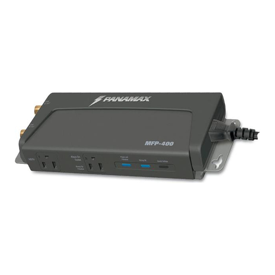
MFP-400 INSTRUCTIONS
Top Mounting
Bracket
Outlet 1
for HDTV
always on
filtration
Outlet 2
for HDTV, or
other accessories
always on filtration
LED Indicators
Power and Filtration
Wiring OK
Unsafe Voltage
IEC plug connects to display
3 ft.
Power Cord
Top and Bottom Mounting Brackets
Straight plug connects
to MFP-400 outlet 1 or 2
The MFP-400 is designed specifically for high definition
flat panel display power filtering (AC noise filtration)
and power protection (surge and over-voltage/under voltage
protection for the AC line).
In addition, it features noise filtration circuitry for both
outlets. A secondary use for this product is for use with
satellite receivers or other accessory equipment.
IMPORTANT SAFETY POINTS
Panamax surge protectors and the connected equipment
must be indoors, in a dry location and in the same building.
Although your Panamax protector is very durable, its
internal components are not isolated from the environment.
Do not install any Panamax product near heat emitting
appliances such as a radiator or heat register. Do not
install this product where excessive moisture is present; for
example near a bathtub, sink, pool, basement floor, fish
tank, etc.
It is not uncommon for a building to be improperly grounded.
In order to protect your equipment, Panamax products
must be plugged into a properly wired and grounded 3-wire
outlet. Additionally, building wiring and grounding must
conform to applicable NEC (USA) or CEC (Canada) codes
for the Panamax protection policy to be valid.
Do not use 2-blade adapters or any other "power strips"
with this product. Use only Panamax extension cords if a
longer cord is required.
NOTE to TV ANTENNA, SATELLITE DISH and CATV
INSTALLERS:
Articles 810.21 and 820.40 of the NEC provide specific
guidelines for proper grounding, and in particular, specify
that the cable ground shall be connected to the grounding
system of the building, as close to the point of cable entry
as practical.
2 AC outlets individually filtered
Both outlets are designated as always on outlets.
Power will be disconnected from the outlets under a fault
condition or tripping of the circuit breaker. When power is
applied to each outlet the corresponding Outlet On LED
will be illuminated.
Over/under voltage shutoff
When the line voltage exceeds the the overvoltage
threshold power is disconnected from both outlets and
the Unsafe Voltage LED turns ON (red).
When the line voltage falls below the under-voltage
threshold, power is disconnected from both outlets and
the Unsafe Voltage LED will turn ON (red).
3 Diagnostic LEDs for maximum safety.
They are designated as follows:
1. Outlets are On – (blue) normally ON; indicates that the
surge protector is functioning properly and that all
connected equipment is protected.
Coax Connectors
(bi-directional)
Right angle plug
IEC plug connects to MFP-400
2. Wiring OK – (blue) When the unit is plugged into a
properly wired outlet, the Wiring OK LED is ON. If it is
plugged into an outlet with reversed L-N wiring or open
ground, the LED is OFF.
3. UNSAFE VOLTAGE –(red) normally OFF, indicates
that incoming voltages are unsafe and the surge protector
has disconnected the power to your connected equipment
when on.
INSTALLATION (AC Power):
1. Turn OFF the power to all equipment that will be
plugged into the unit.
2. Plug the unit into the wall outlet.
3. Verify that the blue "Wiring OK" LED is lit, indicating
that the wall outlet is properly wired and grounded.
4. Plug the equipment to be protected into the Panamax
unit and one at a time, turn each piece of connected
equipment ON and check for correct operation.
5. Audio/Video equipment like HDTV's, receivers, DVD
players, TVs, etc. may be plugged into either outlet.
Both outlets provides power from a "Balanced Double L"
filtration circuit so that EMI/RFI noise is prevented from
reaching your source/display equipment.
Cable/sat/antenna signal protection
Coaxial protection circuits achieve optimum signal quality
from our new coaxial protectors that have the smallest
signal loss on the market – less than 0.5db of attenuation
from 0Hz to 2.2GHz.
Our upgraded coaxial protection has been specifically
designed to virtually eliminate signal loss.
The clamping level of 75V will meet the demands of both
cable and satellite voltage while minimizing exposure to
damaging spikes and surges.
INSTALLATION (Coaxial Lines):
IMPORTANT: Note the position of the LINE and EQUIP
jacks on the Panamax unit. LINE is for the line connection
that comes from the wall or floor jack. EQUIP is for the line
connection to your connected equipment.
NOTE: The CATV/Off-Air Antenna protection circuit in this
model is bi-directional and has been designed to work with
cable TV systems that send pay-per-view ordering
information to the cable company over the coaxial line.
The MFP-400 provides protection for one coaxial line,
compatible with Satellite, CATV, cable modem, or off-air
antenna. Make sure that your equipment is connected to
the proper jacks. When used with diplexers, this protection
circuit must be placed between the diplexer and the
Satellite receiver, it will not protect the diplexer.
Back of Display Mounting procedure:
Universal Mounting Plate
(for horizontal or vertical positioning).
to wall outlet
3 ft.
Power Cord
1. Determine the mounting location on the rear of the
display panel and attach using bolts with low profile
heads for clearance to mount MFP-400 to the
universal mounting plate.
1. Make sure the Panamax protector and all connected
equipment is turned off.
2. Connect the coaxial cable from the CATV system,
antenna or Satellite dish to either iN/OUT (bi-directional)
connector on the Panamax protector.
3. Connect a coaxial cable from the other (bi-directional)
IN/OUT jack on the protector to appropriate input jack on
your TV, DVR, VCR, Satellite receiver or cable modem.
Wall Mounting procedure:
1. Determine the mounting location
on the wall and mark the position
for the top mounting screw.
2. Place a spacer eyelet on one of the #6 pan-head screws
with the flared end of the eyelet toward the wall. Drive the
screw into the wall (use the included drywall anchors for
hollow walls) at the marked location, leaving the eyelet
exposed.
3. Position the key-hole on the unit's top mounting bracket
over the eyelet/screw and slide the unit down to lock the
screwhead into the bracket.
4. Mark the location for the two lower mounting screws
(in the narrow portion of the key-holes) and drive the screws
into the wall using the other 2 spacer eyelets like in step #3.
The included drywall anchors should be used for mounting
on hollow walls
5. Position the protector over the 3 eyelets/screws and slide
the unit down to lock it into place.
6. Using the above procedure allows easy removal of the
unit by sliding the unit up to disengage the brackets from
the eyelets/screws.
Back of Display Mounting procedure:
Universal Mounting Plate (for horizontal or vertical
positioning).
1. Determine the mounting location on the rear of the display
panel and attach using bolts with low profile heads for
clearance to mount MFP-400 to the universal mounting
plate.
2. Position the protector over the 3 eyelets/screws on the
universal plate and slide the unit down to lock it into
place.
Velcro Mounting (optional)
Two pair of 3 in. Velcro strips are included for mounting to
either wall or back of display.
MFP-400
Universal
mounting
plate
Coaxial cable out
Coaxial cable in
to equipment
from wall outlet
2. Position the protector over the 3 eyelets/screws
on the universal plate and slide the unit down to
lock it into place.
TROUBLESHOOTING–
If you are having problems with your surge protector,
read this section.
The "Outlet 1 On / Outlet 2 On" LED is not lit,
there is no AC power to my equipment, or my
equipment doesn't turn on.
• Make sure that the protector is plugged into a
working AC outlet.
• Check all AC power connections.
• Make sure that the protector and connected
equipment are turned on.
• Verify that the "Unsafe Voltage" LED is not lit. If it
is on, the incoming line voltage is either too high or
too low and has been disconnected from your connected
equipment.
• If you still have no power, the protector may be
damaged. Contact Panamax (website or Customer
Support Department) for replacement.
There is no audio or video for my TV, stereo or
VCR.
• Check the coaxial connections, making sure they
are correctly and securely installed.
• If you still have no picture, a problem with your
cable provider's signal may exist.
The Panamax circuit breaker disconnects AC
power from the connected equipment.
• You have exceeded the ampere rating for your
surge protector. As a temporary fix, disconnect one
or more pieces of equipment. Ask your Panamax
dealer about additional Panamax protectors that
may be required.
CAUTION - Do not install this device if
there is not at least 10 meters (30 feet)
or more of wire between the electrical
outlet and electrical service panel.
www.panamax.com
INS00823_EN REV. B
AC line
out to
equipment
AC line in
from wall
outlet
07/09
Advertisement
Table of Contents

Related Manuals for Panamax MFP-400


Summary of Contents for Panamax MFP-400
- Page 1 Over/under voltage shutoff 1. Determine the mounting location on the rear of the display jacks on the Panamax unit. LINE is for the line connection or more of wire between the electrical When the line voltage exceeds the the overvoltage panel and attach using bolts with low profile heads for that comes from the wall or floor jack.
- Page 2 Pour protéger vos équipements, les systèmes Panamax doivent la tension d’entrée est soit trop forte, soit trop faible et l’alimentation de 4. Brancher l'équipement que doit protéger le Panamax et, un à la fois, être branchés dans une prise trifilaire correctement câblée et votre équipement a été...
- Page 3 MFP-400 a la placa de montaje universal. Cable eléctrico de CA 2. Coloque el protector sobre los 3 eyelets/screws en la placa universal y resbale la unidad abajo para bloquearla en lugar.
Need help?
Do you have a question about the MFP-400 and is the answer not in the manual?
Questions and answers