Table of Contents
Advertisement
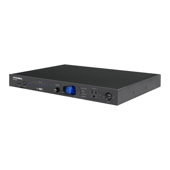
M4315-PRO Instructions
Power Management with Control System Interactive Functionality.
• 15 Amp Capacity M4315-PRO
• 8 Individually Controllable Rear Panel Outlets
• Fully Programmable
• TCP/IP (BlueBOLT™) Installed
• RS-232 Card (Included, not installed)
• Linear Filtration with 3 Isolated LiFT Filter Banks, 76db (5 kHz - 250 kHz), 46 db (250 kHz - 1 MHz)
• One Isolated Filter Bank for High Current Devices, 60db (5 kHz - 450 kHz), 46 db (450 kHz - 1 MHz)
• Front Panel Circuit Breaker
• Integrated Front Rack Ears
• 12 Volt Input Triggering
• Detachable 10 ft. Power Cord
• AVM & Protect-or-Disconnect Circuitry
Important: You will need the BlueBOLT-CV1's unique MAC address and challenge key (provided on the 2 labels
attached to the cover of the Quick Start Guide which is included in the M4315-PRO packaging). One label is
permanently adhered to the Quick Start Guide and the other is removable for your convenience.
Blue
B LT
™
ENABLED
INS00859 REV. D 5/10
Advertisement
Table of Contents

Related Manuals for Panamax M4315-PRO


Summary of Contents for Panamax M4315-PRO
- Page 1 Important: You will need the BlueBOLT-CV1’s unique MAC address and challenge key (provided on the 2 labels attached to the cover of the Quick Start Guide which is included in the M4315-PRO packaging). One label is permanently adhered to the Quick Start Guide and the other is removable for your convenience.
- Page 2 Introduction Thank you for purchasing a Panamax M4315-PRO Power Management with control system interactive functionality, and congratulations on your choice. The M4315-PRO features Panamax’s revolutionary AVM (Automatic Voltage Monitoring) circuit, and our exclusive Linear Filtering Technology (LiFT). To- gether, these technologies comprise precisely what our customers have come to expect from Panamax: uncompromised AC protection and purification.
- Page 3 M4315-PRO’s switched outlets. When the source component is Panamax’s patented power monitoring circuitry constantly monitors the AC line turned off, the voltage trigger signal is also turned off, and the M4315-PRO’s voltage for unsafe voltage conditions such as momentary spikes or prolonged shutdown sequence is initiated.
-
Page 4: Important Safety Instructions
6. CAUTION - Contains Always On Receptacles. To reduce risk of shock - Dis- the apparatus has been damaged in any way, such as power-supply cord or connect M4315-PRO from power source before servicing any equipment con- plug is damaged, liquid has been spilled or objects have fallen into the appa- nected to M4315-PRO. - Page 5 Preset Profile Information PROFILE 1 (P1) DEFAULT OUTLET SEQUENCING (preset profile P1, by outlet #s): Start up: 1→(1 sec)→2→(1 sec)→3→(1 sec)→4→(1 sec)→5→(1 sec)→6→(1 sec)→7→(5 sec)→8 With switching on and off Shut down: 8→(5 sec)→7→(5 sec)→6→(1 sec)→5→(1 sec)→4→(1 sec)→3→(1 sec)→2→(1 sec)→1 BREAKER or holding both REBOOT buttons.
- Page 6 BANK 2 BANK 1 4. CATV/SAT 1 & 2: Universal voltage (±75V clamping), HD 1080i/p ready, 1. Power inlet: M4315-PRO (120 Vac/15 A, IEC 320 C14) do not remove <0.5 dB @ 0 Hz - 2.2 GHz. steel retention clip.
-
Page 7: Troubleshooting
Connect the coaxial line or telephone DSL line from the wall, to M4315- establish connection. PRO signal line pass-through protection circuits. Step 3. Route coaxial cable line or telephone DSL line from the M4315-PRO back to modem/router’s input. BlueBOLT OUTLET 8... - Page 8 Identify Connected Equipment Use this diagram to write in what pieces of equipment are plugged into each outlet for an easy reference. PLEASE NOTE that the outlets start at No. 8 on the left. The outlet indicator lights on the front panel are numbered 1 through 8 left to right. OUTLET OUTLET OUTLET...
- Page 9 RS-232 and Telnet Command Set / Protocol Specifications Command Set/Status Messaging The following commands are applicable when communicating with your M4315-PRO via direct connection using Telnet protocol or the included RS-232 interface. 0. OVERVIEW QUERY: A message sent to the M4315-PRO unit from the 1.2.1...
- Page 10 None 3.5 SWITCH OUTLET Turns a specific outlet on or off. Switching is immediate with no delay. 3. CONTROLLER COMMANDS The following are commands sent by the controlling equipment to the M4315-PRO unit. !SWITCH outlet state<CR> 3.5.1 Command: Note: Responses are only transmitted if unsolicited feedback (§3.9) is enabled.
- Page 11 RS-232 and Telnet Command Set / Protocol Specifications (Continued) 3.7 SET REBOOT DELAY 3.10.2 Action: Sets the linfeed mode to mode. Assign the delay between the last outlet turning off and the beginning of the turn on se- quence in a reboot cycle. 3.10.3 Response: If mode = ON, $LINEFEED = ON<CR>...
- Page 12 LINEFEED = ON PROFILE = 2 4.0.1 Query: ?ID<CR> 3.12.4 Action: P3 configuration below: 4.0.2 Response: $PANAMAX<CR> TRIGGER FOR 1 = BUTTON_1, GREEN_BUTTON $MAX 4315-PRO<CR> TRIGGER FOR 2 = GREEN_BUTTON $FIRMWARE: revision<CR> TRIGGER FOR 3 = BUTTON_2, GREEN_BUTTON TRIGGER FOR 4...
- Page 13 RS-232 and Telnet Command Set / Protocol Specifications (Continued) 4.5 VOLTAGE 5. Responses and Warning Messages Request line voltage. If unsolicited feedback is enabled, the following warning messages will be transmitted under the conditions outlined in their description. 4.5.1 Query: ?VOLTAGE<CR>...
-
Page 14: Fcc Notice
Also, please enclose a note giving your name, address, phone number and a description of the problem. INS00859 REV. D 5/11/10 ® 2010 Panamax LLC, 1690 Corporate Circle, Petaluma, CA 94954 • www.panamax.com • 707-283-5900 • Fax 707-283-5901...
Need help?
Do you have a question about the M4315-PRO and is the answer not in the manual?
Questions and answers