
Related Manuals for NETGEAR FS566 - Switch


Summary of Contents for NETGEAR FS566 - Switch
- Page 1 Installation Guide for the Model FS562 and Model FS566 Fiber Switches NETGEAR, Inc. A Bay Networks Company 4401 Great America Parkway Santa Clara, CA 95054 USA Phone 888-NETGEAR M-FS560NA-0 November 1998...
-
Page 2: Statement Of Conditions
In the interest of improving internal design, operational function, and/or reliability, NETGEAR reserves the right to make changes to the products described in this document without notice. NETGEAR does not assume any liability that may occur due to the use or application of the product(s) or circuit layout(s) described herein. - Page 3 Bestätigung des Herstellers/Importeurs Es wird hiermit bestätigt, daß das Model FS562 Fiber Switch and Model FS566 Fiber Switch gemäß der im BMPT-AmtsblVfg 243/1991 und Vfg 46/1992 aufgeführten Bestimmungen entstört ist. Das vorschriftsmäßige Betreiben einiger Geräte (z.B. Testsender) kann jedoch gewissen Beschränkungen unterliegen. Lesen Sie dazu bitte die Anmerkungen in der Betriebsanleitung.
- Page 4 Defective or damaged merchandise can be returned to your point-of-sale representative. Internet/World Wide Web NETGEAR maintains a World Wide Web home page that you can access at the universal resource locator (URL) http://NETGEAR.baynetworks.com. A direct connection to the Internet and a Web browser such as Internet Explorer or...
-
Page 5: Table Of Contents
Contents Chapter 1 Introduction Benefits of Using Switching Technology .................1-1 Types of Ethernet Switches ....................1-2 Model FS562/FS566 Switch Overview ................1-2 Features ..........................1-3 Chapter 2 Physical Description Front Panel ........................2-1 Fast Ethernet Ports ....................2-3 100BASE-FX Fiber Ports ..................2-4 Normal/Uplink Push Button ..................2-4 LEDs ........................2-5 Rear Panel ........................2-7 FDX/HDX Duplex Toggle Switches ................2-8... - Page 6 Chapter 4 Installation Preparing the Site ......................4-1 Checking Package Contents ...................4-1 Installing a Switch ......................4-2 Installing the Switch on a Flat Surface ..............4-2 Installing the Switch in a Rack .................4-3 Connecting Devices to the Switch ..................4-4 Verifying Installation ......................4-5 Chapter 5 Troubleshooting Network Adapter Cards ....................5-2 Configuration ........................5-2...
- Page 7 Figures Figure 2-1. Front Panel of the Model FS562 Switch ...........2-1 Figure 2-2. Front Panel of the Model FS566 Switch ...........2-2 Figure 2-3. The Vista RJ-45 Connector with Built-In LEDs ........2-3 Figure 2-4. 100BASE-FX Fiber Connection ...............2-4 Figure 2-5. Rear Panel of the Model FS562 Switch ...........2-7 Figure 2-6.
- Page 8 viii Figures...
- Page 9 Tables Table 2-1. LED Descriptions ..................2-6 Table 5-1. Troubleshooting Information ..............5-1 Table B-1. RJ-45 Plug and Vista RJ-45 Connector Pin Assignments ...... B-2 Table C-1. Electrical Requirements of Category 5 Cable ......... C-2 Table C-2. Electrical Requirements of Fiber Optic Cable ......... C-5 Tables...
- Page 10 Tables...
-
Page 11: Introduction
Chapter 1 Introduction Congratulations on your purchase of the NETGEAR ™ Model FS562 8-Port Fast Ethernet Fiber Switch or the Model FS566 12-Port Fast Ethernet Fiber Switch. These switches provide you with a low-cost, high-performance network solution and are designed to support power workgroups operating at either 10 megabits per second (Mbps) or 100 Mbps. -
Page 12: Types Of Ethernet Switches
Installation Guide for the Model FS562 and Model FS566 Fiber Switches Ethernet switches provide private, dedicated, 10 Mbps (or 100 Mbps) capacity to each connected PC/server or hub/workgroup segment, which is significantly higher than in a shared environment. The higher bandwidth enables the use of applications such as multimedia, imaging, video, or high- performance client-server functions among users who are spread out over the network. -
Page 13: Features
Installation Guide for the Model FS562 and Model FS566 Fiber Switches The Model FS562/FS566 switch can be used to partition a 10 Mbps or 100 Mbps network to enhance the capacity of the network to support advanced applications. In addition, the switch provides a link between traditional 10 Mbps networks and faster 100 Mbps networks. - Page 14 Installation Guide for the Model FS562 and Model FS566 Fiber Switches • Switch-selectable autonegotiating or full-duplex mode of operation for UTP ports Full-duplex mode doubles throughput of point-to-point connections by letting individual ports transmit and receive concurrently when the other end also supports full-duplex mode. The default is half-duplex if the connected device does not support N-way negotiation.
-
Page 15: Physical Description
Chapter 2 Physical Description This chapter describes the hardware features of the NETGEAR Model FS562 and FS566 Fast Ethernet Fiber Switches. Front Panel For easier management and control of the Model FS562 switch, familiarize yourself with the ports, LEDs, and Normal/Uplink push button on the front panel of the switch, as illustrated in Figure 2-1. -
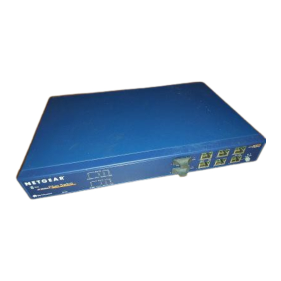
Page 16: Figure 2-2. Front Panel Of The Model Fs566 Switch
Installation Guide for the Model FS562 and Model FS566 Fiber Switches The front panel of the Model FS566 switch, as illustrated in Figure 2-2, is almost identical to that of the Model FS562 switch. The main difference is the number of fiber ports and corresponding LEDs. -
Page 17: Fast Ethernet Ports
Installation Guide for the Model FS562 and Model FS566 Fiber Switches Fast Ethernet Ports Figure 2-1 Figure 2-2 show, the Model FS562 and Model FS566 switches are equipped with six autosensing 10/100 Mbps Fast Ethernet UTP ports. The network access speed for the 10/100 Mbps ports is automatically sensed and displayed on the front panel by the 10 Mbps or 100 Mbps LEDs. -
Page 18: 100Base-Fx Fiber Ports
Installation Guide for the Model FS562 and Model FS566 Fiber Switches 100BASE-FX Fiber Ports The Model FS562 switch has two 100BASE-FX fiber ports; the Model FS566 switch has six. These ports operate at 100 Mbps exclusively and provide a standard duplex SC connector for 62.5/125- m multimode fiber optic cable. -
Page 19: Leds
Installation Guide for the Model FS562 and Model FS566 Fiber Switches LEDs The LEDs on the front panel of the switch and two vista LEDs on each RJ-45 connector allow you to identify the following information: • Status of the switch power supply •... - Page 20 Installation Guide for the Model FS562 and Model FS566 Fiber Switches Table 2-1 describes each LED on the front panel of the Model FS562/FS566 switch. Table 2-1. LED Descriptions Label Color Activity Description Power Green Power is supplied to the switch. Power is disconnected.
-
Page 21: Rear Panel
Installation Guide for the Model FS562 and Model FS566 Fiber Switches Rear Panel As illustrated in Figure 2-5 Figure 2-6, the rear panels have a full-duplex (FDX) and half-duplex (HDX) toggle switch, an FDX and auto-duplex (AUTO) toggle switch, a standard AC power receptacle, and fans for cooling. -
Page 22: Fdx/Hdx Duplex Toggle Switches
Installation Guide for the Model FS562 and Model FS566 Fiber Switches FDX/HDX Duplex Toggle Switches The duplex mode (full or half) is controlled by the dip switches on the rear panel of the Model FS562/FS566 switch. Both the sending port and the receiving port must be set to the same duplex mode. -
Page 23: Applications
Chapter 3 Applications This chapter presents an overview of the levels of service provided by incorporating the technology of the Model FS562/FS566 switch into your network. The Model FS562/FS566 switch is designed to provide flexibility in configuring your network connections. Each switch can be used as a standalone device or can be used with 10 Mbps or 100 Mbps hubs or other interconnection devices in various configurations. -
Page 24: Desktop Switching
Installation Guide for the Model FS562 and Model FS566 Fiber Switches Desktop Switching Figure 3-1 illustrates the Model FS562 Fiber Switch used as a desktop switch to build a small network that enables users to have 100 Mbps access to a file server. The Model FS566 Fiber Switch can also be used in this manner. -
Page 25: Segment Switching
The Model FS562 and Model FS566 switches can segment a network into multiple connected pieces, increasing overall bandwidth and throughput. Figure 3-2 illustrates the Model FS562 Fiber Switch and the Model FS566 Fiber Switch segmenting networks that are built with a NETGEAR Model FE508 Fast Ethernet Hub. MODEL FS562... -
Page 26: Extending A Network
Installation Guide for the Model FS562 and Model FS566 Fiber Switches Extending a Network As a result of signal degradation, unshielded twisted pair (UTP) cable allows for a maximum distance of only 100 meters between each node connection. By adding a fiber switch between network segments, the network is expanded by as much as 2 kilometers (km). -
Page 27: Bridging From 10Base-T To 100Base-Tx Networks
100 Mbps while remaining connected to the rest of the network. Figure 3-4 illustrates the Model FS562 Fiber Switch integrated with the NETGEAR Model EN516 Ethernet Hub and the NETGEAR Model FE516 Fast Ethernet Hub. -
Page 28: High-Bandwidth File Servers
Figure 3-5 illustrates the Model FS566 Fiber Switch integrated with two NETGEAR Model FE508 Fast Ethernet Hubs. A full-duplex configurable adapter card installed in the server provides up to 200 Mbps maximum data throughput. FS566... -
Page 29: Installation
Chapter 4 Installation This chapter describes the installation procedures for the Model FS562/FS566 switch. Preparing the Site Before you begin installing the switch, prepare the installation site. Make sure the operating environment meets the physical requirements of the switch, as described in Appendix A, “Technical Specifications.”... -
Page 30: Installing A Switch
To qualify for product updates and product warranty registration, fill in the Warranty and Owner Registration Card within 30 days of purchase and return it to NETGEAR, Inc. Installing a Switch To install a switch on a desktop, on another flat surface, or in a rack: Unpack the switch. -
Page 31: Installing The Switch In A Rack
Installation Guide for the Model FS562 and Model FS566 Fiber Switches Installing the Switch in a Rack For mounting the switch in a standard 19-inch rack, you need the following tools and materials: • Two mounting brackets supplied from the Rack Mount Kit •... -
Page 32: Connecting Devices To The Switch
Installation Guide for the Model FS562 and Model FS566 Fiber Switches Install any additional devices in your stack. For proper ventilation, make sure that the switch has at least 2 inches of space on each side and 5 inches of space at the back. It is very important that the fans located in the rear panel are not blocked. -
Page 33: Verifying Installation
Installation Guide for the Model FS562 and Model FS566 Fiber Switches Set the FDX or AUTO switches on the rear panel for the duplex mode. A hub and repeater use a common collision domain for all communications and cannot support full-duplex mode. -
Page 35: Troubleshooting
File transfer is slow or Half- or full-duplex setting Make sure the 10/100 Mbps port is set to performance degradation on the NETGEAR switch auto-duplex (AUTO) mode when connecting the is a problem. and the connected device switch to a repeater or hub. For instructions on are not the same. -
Page 36: Network Adapter Cards
If required, verify the integrity of the switch by resetting the switch. Turn power to the switch off and then back on. If the problem continues and you have completed all the preceding diagnoses, contact your NETGEAR point-of-sale representative. Troubleshooting... -
Page 37: Technical Specifications
Appendix A Technical Specifications This appendix provides technical specifications for the Model FS562 Fiber Switch and the Model FS566 Fiber Switch. General Specifications Network Protocol and Standards Compatibility ISO/IEC 802-3i 10BASE-T IEEE 802.3u 100BASE-TX IEEE 802.3u 100BASE-FX Data Rate 10 Mbps differential Manchester encoded, IEEE 802.3 100 Mbps with 4B5B encoding and MLT-3 physical interface for 100BASE-TX 100 Mbps 1300 nm fiber-PMD interface for 100BASE-FX Interface... - Page 38 Installation Guide for the Model FS562 and Model FS566 Fiber Switches Physical Specifications Dimensions: (W) 13 by (H) 1.7 by (D) 8 in. (W) 33.0 by (H) 4.3 by (D) 20.3 cm Weight: 5.3 lb 2.5 kg Environmental Specifications Operating temperature: to 40 Storage temperature: to 104...
- Page 39 Installation Guide for the Model FS562 and Model FS566 Fiber Switches Safety Agency Approvals CE mark, commercial UL listed (UL 1950) CSA certified (CSA 22.2 #950) TUV licensed (EN 60 950) Performance Specifications Frame filter rate: 14,800 frames/second, maximum on 10 Mbps port 148,000 frames/second maximum on 100 Mbps port Frame forward rate: 14,800 frames/second, maximum on 10 Mbps port...
-
Page 41: Connector Pin Assignments
Appendix B Connector Pin Assignments This appendix provides information about the RJ-45 plug and the vista RJ-45 connector used for the Model FS562 Fiber Switch and the Model FS566 Fiber Switch. RJ-45 Plug and Vista RJ-45 Connector In a Fast Ethernet network, it is important that all 100BASE-T certified Category 5 cabling use RJ-45 plugs. -
Page 42: Duplex Sc Plug And Duplex Sc Connector
Installation Guide for the Model FS562 and Model FS566 Fiber Switches Table B-1 lists the pin assignments for the RJ-45 plug and the vista RJ-45 connector. Table B-1. RJ-45 Plug and Vista RJ-45 Connector Pin Assignments Normal Assignment Uplink Assignment on Ports 1 to 16 on Port 16 Input Receive Data +... -
Page 43: Appendix C Cabling Guidelines
Appendix C Cabling Guidelines This appendix provides specifications for cables used for the Model FS562/FS566 switch. Fast Ethernet Cable Guidelines Fast Ethernet uses UTP cable, as specified in the IEEE 802.3u standard for 100BASE-TX. The specification requires Category 5 UTP cable consisting of either 2-pair or 4-pair twisted insulated copper conductors bound in a single plastic sheath. -
Page 44: Category 5 Cable Lengths
Installation Guide for the Model FS562 and Model FS566 Fiber Switches Category 5 Cable Lengths Category 5 distributed cable that meets ANSI/EIA/TIA-568-A building wiring standards can be a maximum of 328 feet (100 meters) in length, divided as follows: • 20 feet (6 meters) between the hub and the patch panel (if used) •... -
Page 45: Twisted Pair Cables
Installation Guide for the Model FS562 and Model FS566 Fiber Switches Twisted Pair Cables For two devices to communicate, the transmitter of each device must be connected to the receiver of the other device. The crossover function is usually implemented internally as part of the circuitry in the device. -
Page 46: Patch Panels And Cables
If you are using patch panels, make sure that they meet the 100BASE-TX requirements. NETGEAR recommends Category 5 UTP cable for all patch cables and work area cables to ensure that your UTP patch cable rating meets or exceeds the distribution cable rating. -
Page 47: Fiber Cable Specifications
Installation Guide for the Model FS562 and Model FS566 Fiber Switches Fiber Cable Specifications Table C-2 lists the electrical requirements of fiber cable. Table C-2. Electrical Requirements of Fiber Optic Cable Specification Fiber Optic Cable Number of strands Cable type 62.5/125- multimode fiber optic cable Numerical aperture... -
Page 49: Index
Index Numbers connections to other devices, 4-4 10/100 Mbps ports, 2-1 crossover twisted pair cable, 4-4, C-3 100 Mbps LEDs, 2-6 customer support, iv 10BASE-T to 100BASE-TX networks, bridging, 3-5 desktop switching, 1-2, 3-2 applications duplex toggle switches, 1-2, 2-8, 4-5 bridging from 10BASE-T to 100BASE-TX networks, 3-5 desktop switching, 3-2... - Page 50 LEDs (table), 2-5 segment switching, 1-2, 3-3 Link LED, 2-6 server connections, 3-6 site preparation, 4-1 straight-through twisted pair cable, 4-4, C-3 switches, duplex toggle, 1-2, 2-8, 4-5 MAC layer device, 1-3 switches, overview, 1-2 MDI. See uplink switching technology MDI-X.
Need help?
Do you have a question about the FS566 - Switch and is the answer not in the manual?
Questions and answers