
Related Manuals for DH Instruments PG7601-SYS-AF


Summary of Contents for DH Instruments PG7601-SYS-AF
- Page 1 PG7601-SYS-AF™ Gas Operated Piston Gauge Pressure Calibration System Operation and Maintenance Manual NSN 6695-01-551-5125 Consists of Base System and Exchange Pack © 2007 DH Instruments, a Fluke Company...
- Page 2 © 2007 DH Instruments, a Fluke Company All rights reserved. Information in this document is subject to change without notice. No part of this document may be reproduced or transmitted in any form or by any means, electronic or mechanical, for any purpose, without the express written permission of DH Instruments, a Fluke Company.
-
Page 3: Table Of Contents
SETTING UP THE PLATFORM ........................25 3.3.2 SETTING UP THE PRESSURE CONTROLLER ..................26 3.3.3 SYSTEM PRESSURE INTERCONNECTIONS....................26 3.3.4 SETTING UP THE MASS SET ........................27 3.3.5 INSTALLING A PISTON-CYLINDER MODULE INTO THE PLATFORM............28 Page I © 2007 DH Instruments, a Fluke Company... - Page 4 COMMANDS FOR ZERO PRESSURE, ENDING A TEST ..............73 4.3.12 [P OR M], SET PRESSURE TO MASS OR MASS TO PRESSURE OPERATING MODE......73 4.3.13 ] AND [ ], [←], MANUAL CONTROL OF MOTORIZED ROTATION ..........74 © 2007 DH Instruments, a Fluke Company Page II...
-
Page 5: Table Of Contents
COMMAND DESCRIPTIONS........................121 5.3.4.1 IEEE STD. 488.2 COMMON AND STATUS COMMANDS .............121 5.3.4.2 PG7601-AF COMMANDS ........................123 STATUS SYSTEM..........................148 5.4.1 STATUS REPORTING SYSTEM .......................149 5.4.1.1 STATUS BYTE REGISTER ........................149 5.4.1.2 STANDARD EVENT REGISTER ......................150 Page III © 2007 DH Instruments, a Fluke Company... - Page 6 PROCEDURE ............................201 7.3.4.3 CALCULATING AND UPDATING PISTON-CYLINDER TEMPERATURE SENSOR INFORMATION..201 7.3.5 CALIBRATION OF RESIDUAL VACUUM GAUGE ...................202 7.3.5.1 OVERVIEW ............................202 7.3.5.2 PROCEDURE ............................203 7.3.5.3 CALCULATING AND UPDATING VACUUM GAUGE CALIBRATION INFORMATION ......204 © 2007 DH Instruments, a Fluke Company Page IV...
- Page 7 CONVERSION OF NUMERICAL VALUES..................213 9.1.1 PRESSURE..............................213 DEFINED PRESSURE CALCULATIONS ....................213 9.2.1 PG7601-AF ..............................215 9.2.2 FLUID HEADS ............................215 9.2.2.1 FLUID HEAD COMPONENTS .......................215 9.2.2.2 OVERALL FLUID HEAD CORRECTION ....................217 GLOSSARY............................217 WARRANTY STATEMENT ........................219 Page V © 2007 DH Instruments, a Fluke Company...
- Page 8 PG7601-SYS-AF™ OPERATION AND MAINTENANCE MANUAL © 2007 DH Instruments, a Fluke Company Page VI...
-
Page 9: Tables
Table 37. PG7601 Illustrated Parts Breakdown for PPC3 Manifold detail (see Figure 35)....170 Table 38. PG7601 Illustrated Parts Breakdown for PK-7601-P-AF (see Figure 36) ......171 Table 39. PG7601 Illustrated Parts Breakdown for Accessories Kit (see Figure 37)......172 Page VII © 2007 DH Instruments, a Fluke Company... - Page 10 Table 43. Troubleshooting checklist ......................209 Table 44. Pressure unit of measure conversions ..................213 Table 45. Defined pressure calculation variables ..................214 Table 46. DHI Authorized Service Providers ................... 219 © 2007 DH Instruments, a Fluke Company Page VIII...
- Page 11 Figure 21. Pressure controller MAIN run screen display fields..............52 Figure 22. Status byte register......................... 149 Figure 23. Top Level Illustrated Parts Breakdown for PG7601-SYS-AF..........155 Figure 24. PG7601 Illustrated Parts Breakdown for Mass Sets, Cases, and Covers ......156 Figure 25.
- Page 12 PG7601-SYS-AF™ OPERATION AND MAINTENANCE MANUAL © 2007 DH Instruments, a Fluke Company Page X...
-
Page 13: A B O U T T H I S M A N U Al
ABOUT THIS MANUAL This manual provides the user with the information necessary to operate and maintain a PG7601-SYS-AF gas operated piston gauge system. Before using the manual, take a moment to familiarize yourself with the Table of Contents structure. All first time PG7601-AF users should read Section 2 and 4. Section 5 covers remote communication with an external computer. - Page 14 PG7601-SYS-AF™ OPERATION AND MAINTENANCE MANUAL © 2007 DH Instruments, a Fluke Company Page XII...
-
Page 15: 1. Introduction
Pressure is defined by balancing it against the force exerted by a known mass accelerated by gravity on the effective area of a piston-cylinder. PG7601-SYS-AF covers the pressure range of 7 to 7000 kPa (1 to 1 000 psi) in absolute and gauge modes with semi-automated operation and state of the art measurement uncertainty. -
Page 16: Pressure Measurements
PG Terminal Hitachi 64180 Communication ports COM1: Host computer communications RS232 COM2: Not used (may be used for optional external barometer or vacuum gauge) COM3: PPC3 pressure controller communications IEEE-488 Host comptuer © 2007 DH Instruments, a Fluke Company Page 2... -
Page 17: Embedded Features
Motorized, intelligent piston drive system based measured rotation rate with operator alert and manual override. • Integrated automated pressure control with PPC3-7M-AF pressure controller. • Full RS232 and IEEE-488 communications with multi-level commands to set and read all instrument functions. Page 3 © 2007 DH Instruments, a Fluke Company... -
Page 18: Measurement Of Ambient And Instrument Conditions
(Rate and deceleration) Range 2 to 99 rpm Resolution 1 rpm Vacuum Range 0 to 20 Pa Resolution 0.1 Pa ± 0.1 Pa or 10 % of reading, whichever is greater Measurement uncertainty © 2007 DH Instruments, a Fluke Company Page 4... -
Page 19: Piston-Cylinder Modules (Pc-7100/7600-10-L, -50, -200)
1. INTRODUCTION 1.1.3 PISTON-CYLINDER MODULES (PC-7100/7600-10-L, -50, -200) The PG7601-SYS-AF piston-cylinders are integrated modules including mounting hardware delivered in individual shipping and storage bullet cases. PC-7100/7600-10-L Nominal mass to pressure 10 kPa/kg (1.5 psi/kg) Range 7 to 350 kPa (1 to 50 psi) -
Page 20: Mass Set (Ms-7001-35-Af)
± 20 ppm of nominal value Adjustment tolerance ± 8 mg Uncertainty in measured value Trim masses < 50g Adjustment tolerance Adjusted to nominal value ± 1 mg Uncertainty in measured value © 2007 DH Instruments, a Fluke Company Page 6... -
Page 21: Pressure Controller (Ppc3-7M-Af)
0.5 l (1 qt) 18.9 m /h (11.1 cfm) Nominal pumping speed 16.5 m /h (9.7 cfm) Pumping speed Ultimate total pressure 0.2 Pa (1.5 mTorr) Pressure connections (intake KF25 and exhauts) Page 7 © 2007 DH Instruments, a Fluke Company... - Page 22 PG7601-SYS-AF™ OPERATION AND MAINTENANCE MANUAL © 2007 DH Instruments, a Fluke Company Page 8...
-
Page 23: S Y S T E M A N D C O M P O N E N T O V E R V I E W A N D D E S C R I P T I On
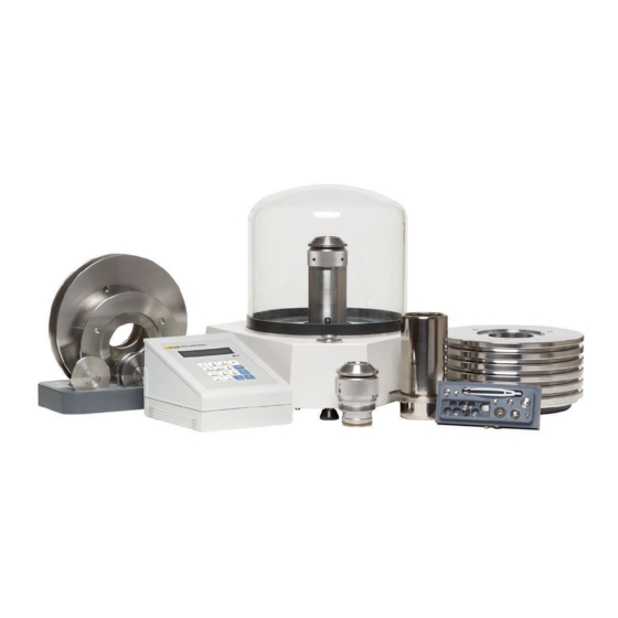
SYSTEM OVERVIEW (PG7601-SYS-AF) PG7601-SYS-AF is a very high performance pressure calibration system for the validation and calibration of pressure measuring devices using gas as the pressurized medium in the range of 7 to 7000 kPa (1 to 1 000 psi). - Page 24 8. RS232 cable, pressure controller to platform 18. Main mass stack 19. Fractional mass tray 9. PPC3-7M-AF pressure controller 10. PG Terminal to platform cable Figure 1. System, PG7601-SYS-AF, standard installation © 2007 DH Instruments, a Fluke Company Page 10...
-
Page 25: Figure 2. System, Pg7601-Sys-Af, Pneumatic Schematic
Vacuum vent valve 4. Vacuum shutoff valve Platform shutoff valve 5. Piston-cylinder module 10. Control vacuum supply Figure 2. System, PG7601-SYS-AF, pneumatic schematic 1. Electrical power cords 4. PG7601-SYS-AF system remote communications (RS232) 2. PG Terminal to PG7601-AF platform data and power connection 5. -
Page 26: Piston Gauge Platform And Terminal (Pg7601-Af)
PG7601-SYS-AF™ OPERATION AND MAINTENANCE MANUAL PISTON GAUGE PLATFORM AND TERMINAL (PG7601-AF) The heart of the PG7601-SYS-AF is the PG7601-AF gas operated piston gauge and its piston-cylinder modules and mass set. The PG7601-AF operates on the principle of the piston gauge in which pressure is defined by balancing it against a known force on a known area (see Figure 4). -
Page 27: Platform
7. VACUUM port, for vacuum vent valve 3. COM1 (RS232) - remote host communications 8. TEST port, for connection to test system 4. Ambient temperature sensor 9. PG Terminal port Figure 5. Platform, PG7601-AF, rear view Page 13 © 2007 DH Instruments, a Fluke Company... -
Page 28: Pg Terminal
PG TERMINAL The PG Terminal houses the PG platform power supplies and provides the local user interface for interaction with the PG7601-SYS-AF system. The front panel assembly provides a 2 x 20 vacuum fluorescent display and a 4 x 4 membrane keypad for local user interface. -
Page 29: Piston-Cylinder Modules (Pc-7100/7600-10-L, -50, -200)
The piston-cylinder module is mounted in the PG7601-AF platform. The piston-cylinder precisely converts pressure to a proportional force (see Section 4.1.1). There are three piston-cylinder modules for three different pressure ranges. Figure 8. Piston-cylinder modules, PC-7100/7600-10-L, -50, -200 Page 15 © 2007 DH Instruments, a Fluke Company... -
Page 30: Mass Set (Ms-7001-35-Af)
The PPC3-7M-AF pressure controller is a component of the PG7601-SYS-AF system. It can also act as a stand alone component. For information on use of PPC3-7M-AF outside of the PG7601-SYS-AF system, see the PPC3 Operation and Maintenance Manual. -
Page 31: Figure 10. Pressure Controller, Ppc3-7M-Af, Front Panel
5. COM1 connector (PG7601-AF 12. Pressure connection, TEST(-) communications) 13. Pressure connection, EXHAUST 6. Drivers (12 V) connector 14. Pressure connection, SUPPLY 7. Power switch Figure 11. Pressure controller, PPC3-7M-AF, rear panel Page 17 © 2007 DH Instruments, a Fluke Company... -
Page 32: Reference Vacuum Pump (D16B)
9. Oil drain plug 4. Handle 10. Oil level sight glass Power switch 11. Gas ballast valve 6. Oil fill plug Figure 12. Reference vacuum pump, D16B, front and side views © 2007 DH Instruments, a Fluke Company Page 18... -
Page 33: Unpacking And Inspection
3.1.1 UNPACKING AND INSPECTION OF PG7601-BAS-AF BASE SYSTEM The PG7601-BAS-AF is the PG7601-SYS-AF gas piston gauge base system. It includes the system operational components but not the piston-cylinder modules and mass sets which are in the PG7601-EXC-AF exchange pack. Check that all items included in the PG7601-BAS-AF base system are present and have NO visible signs of damage. -
Page 34: Pressure Controller (Ppc3-7M-Af)
Quick connector stem, 1/4 in. NPT F 102117 1 ea. Quick connector stem, 1/8 in. NPT F 102116 1 ea. Quick connector stem, AN4 M 102115 1 ea. Quick connector stem, 1/4 in. Swage 101977 © 2007 DH Instruments, a Fluke Company Page 20... -
Page 35: Vacuum Interconnections Kit (Pk-7601-V-Af)
3.1.2 UNPACKING AND INSPECTION OF PG7601-EXC-AF EXCHANGE PACKAGE The PG7601-EXC-AF is the PG7601-SYS-AF gas piston gauge system’s metrological elements. It includes the piston-cylinder modules and mass set. Check that all items included in the PG7601-EXC-AF exchange package are present and have NO visible signs of damage. -
Page 36: Piston-Cylinder Modules (Pc-7100/7600-10-L, Pc-7100/7600-50, Pc-7100/7600-200) And Accessories
PG7601-AF system. To unpack: Carefully remove each mass from the transit case. Do not remove masses from their plastic bags until ready to install them (see Section 3.3.4). © 2007 DH Instruments, a Fluke Company Page 22... -
Page 37: Documentation And Accessories
550300 SITE REQUIREMENTS See Section 2.1, Figure 1 for an illustration of the PG7601-SYS-AF standard installation. When selecting and preparing a site to set up the PG7601-SYS-AF system, the following should be considered: • Ambient conditions: To achieve optimum metrological performance, ambient conditions should be controlled and maintained within the following: ♦... - Page 38 PG7601-AF, may affect piston sensitivity. • Bench space: The recommended standard setup for the PG7601-SYS-AF system requires a bench space of at least 165 cm x 56 cm (65 in. x 22 in.) (see Section 2.1, Figure 1).
-
Page 39: Physical Setup
Before setting up the PG7601-AF system, see Section 2.1, Figure 1 for an illustration of the PG7601- SYS-AF standard installation and Section 3.2 for information on site requirements. To set up the PG7601-SYS-AF components for operation proceed as follows in the specified order: Set up the PG7601-AF platform (see Section 3.3.1). -
Page 40: Setting Up The Pressure Controller
PG7601-SYS-AF™ OPERATION AND MAINTENANCE MANUAL 3.3.2 SETTING UP THE PRESSURE CONTROLLER Refer to Section 2.1, Figure 1 for an illustration of the PG7601-SYS-AF standard installation and Section 3.2 for information on site requirements. To set up the PPC3-7M-AF pressure controller proceed as follows: Install the rubber feet caps on the PPC3-7M-AF if desired. -
Page 41: Setting Up The Mass Set
1, then 2. The trim mass case can be placed near the mass tray as desired. Install the mass set dust covers (included in mass set accessories) if desired. Page 27 © 2007 DH Instruments, a Fluke Company... -
Page 42: Installing A Piston-Cylinder Module Into The Platform
Figure 13. Piston-cylinder module installation Low torque manual rotation is all that should be required to fully seat the piston-cylinder module into the PG7601-AF mounting post. Never force the piston-cylinder module into the mounting post. © 2007 DH Instruments, a Fluke Company Page 28... -
Page 43: Setting Up The Reference Vacuum Pump And Vacuum Interconnections
SETTING UP THE REFERENCE VACUUM PUMP AND VACUUM INTERCONNECTIONS Refer to Section 2.1, Figure 1 for an illustration of the PG7601-SYS-AF standard installation and identification of components. See Section 2.6 for detail on the D16B vacuum pump. See Section 3.2 for information on site requirements. -
Page 44: Connecting Control Vacuum Supply
PPC3-7M-AF SUPPLY port and the PPC3 is NOT in the vent ON condition, there may be a constant gas exhaust through the PPC3 EXHAUST port. POWER UP AND VERIFICATION This section assumes that the physical setup of the PG7601-SYS-AF system has been completed (see Section 3.3). 3.4.1... -
Page 45: Check That On-Board Piston-Cylinder Module And Mass Set Digital Ids Are Correct
To verify that the ambient condition measurements are operating properly, proceed as follows: • Display current ambient condition readings: Press [AMBIENT] on the PG7601-AF Terminal. The ambient conditions run screen is displayed (see Section 4.3.6). Page 31 © 2007 DH Instruments, a Fluke Company... -
Page 46: Turn On Autogen And Autorotate
With the vacuum shutoff valve closed, turn ON the vacuum pump using its power switch. 3.4.10 SET A GAUGE MODE PRESSURE, CHECK A FUNCTIONS OTATE This section assumes that the PG7601-AF system has already been set up, including pressure interconnection (see Section 3.3). © 2007 DH Instruments, a Fluke Company Page 32... - Page 47 Press [ENTER/SET P] and enter <0> to vent the system (see Section 4.3.11.3). If automated rotation is not ON, be sure to stop the rotation of the piston manually by holding [ ] and then pressing [←]before pressing [ENTER]. Page 33 © 2007 DH Instruments, a Fluke Company...
-
Page 48: Check Piston Behavior Measurements
On initial vacuum pull down, with the pump fully warmed up, the vacuum should reach the default Ready limit (see Section 4.1.3.3) of 5 Pa (0.000725 psi) in less than 3 min 30 sec. Subsequent pull down should be on the order of 1 minute. © 2007 DH Instruments, a Fluke Company Page 34... - Page 49 Open vacuum vent valve on the back of the PG7601-AF platform. Wait for pressure under bell jar to return to ambient. This takes about 40 seconds. Remove bell jar. Page 35 © 2007 DH Instruments, a Fluke Company...
-
Page 50: Additional Precautions To Take To Make Good Pressure Measurements
(see Section 4.3.8). • Be sure that the platform shutoff valve on the PG7601-AF TEST port is open (The knob should be rotated counter clockwise until it stops). © 2007 DH Instruments, a Fluke Company Page 36... -
Page 51: Operating Principles
For this reason, PG7601-AF includes extensive features to monitor the behavior and conditions of the piston-cylinder as well as ambient conditions that affect pressure definition. Page 37 © 2007 DH Instruments, a Fluke Company... -
Page 52: Pressure Control, Manual And Automated
SETUP files (see Section 4.4). Once PG7601-SYS-AF system has been set up, it is used in day-to-day operation either to define pressures applied to a device or system under test or to measure a stable pressure. -
Page 53: Pressure Ready/Not Ready Indication
SETUP file and can be customized by the user (see Section 4.4). Piston position Ready/Not Ready character indications include: <*> Piston position Ready (within the position limits specified in the current SETUP file) (see Section 4.4). Page 39 © 2007 DH Instruments, a Fluke Company... -
Page 54: Piston Rotation Ready/Not Ready
The vacuum reference Ready/Not Ready character indicates Ready or Not Ready based on the value of reference vacuum when making measurements in absolute by vacuum mode. This ensures that measurements of absolute © 2007 DH Instruments, a Fluke Company Page 40... -
Page 55: Piston Position
Piston float target: Applies only when AutoGen automated pressure control is ON (see Section 4.3.9). The float target is the position to which the PPC3-7M-AF must set the piston before control is stopped and a Ready condition can occur. Page 41 © 2007 DH Instruments, a Fluke Company... -
Page 56: Mass Loading Protocol
The mass value shown in the MAIN run screen (see Section 4.2.1.2) is always the actual mass value. The © 2007 DH Instruments, a Fluke Company Page 42... - Page 57 USE the piston (0.2 kg) + the mass loading bell (0.3 kg) + the 4.5 kg makeup mass. DO NOT USE the piston + the mass loading bell + 2 kg #1 + 2 kg #2 + 0.5 kg #1. Page 43 © 2007 DH Instruments, a Fluke Company...
- Page 58 For PG7601-AF mass loading protocol to operate properly, the mass set in use must be EXACTLY the mass set that is defined by the active mass set digital ID (see Section 4.5.1.10). © 2007 DH Instruments, a Fluke Company Page 44...
-
Page 59: User Interface
4. GENERAL OPERATION USER INTERFACE The local user interface of the PG7601-SYS-AF system is the PG7601-AF’s PG Terminal keypad and display. In normal operation, the PPC3-7M-AF pressure controller operates automatically under the control of the PG7601-AF platform and the PPC3-7M-AF front panel is not used. The exception is when the pressure controller is used manually and controlled by the operator through its front panel direct pressure control keys (see Section 4.2.2.2). -
Page 60: Main Run Screen
Ready/Not Ready criterion <↑>: Not Ready, piston too high Ready indicator <↓>: Not Ready, piston too low <?>: Piston position not available Flashes if condition Not Ready and piston is floating © 2007 DH Instruments, a Fluke Company Page 46... -
Page 61: Figure 17. Platform Main Run Screen Display Fields
The PG Terminal has a screen saver function that causes the display to dim if NO key is pressed for 10 minutes. Pressing a key restores full power to the display. The screen saver activation time can be changed or screen saving can be completely disabled (see Section 4.5.4.1). Page 47 © 2007 DH Instruments, a Fluke Company... -
Page 62: General Function/Menu Flow Chart
Invalid key press Three rapid valid key press beeps. Piston was at low Piston left end of stroke high or low stop or high stop and just entered spring zone (see Section 4.1.4). © 2007 DH Instruments, a Fluke Company Page 48... -
Page 63: Pressure Controller
The PPC3-7M-AF pressure controller is a component of the PG7601-SYS-AF system. It can also act as a stand alone component. For information on use of PPC3-7M-AF outside of the PG7601-SYS-AF system, see the PPC3 Operation and Maintenance Manual. -
Page 64: Direct Pressure Control Keys
PPC3 range. The value can be adjusted using [SETUP], <3jog> or pressing both the up and down jog keys simultaneously. The [ ] and [ keys are not normally used when PPC3-7M-AF is part of a PG7601-SYS-AF system. © 2007 DH Instruments, a Fluke Company Page 50... -
Page 65: Main Run Screen
Do not change units of measure ([UNIT]) or measurement mode ([MODE]). 4.2.2.3 MAIN RUN SCREEN In typical PG7601-SYS-AF system operation, the PPC3-7M-AF pressure controller keypad is not used. Occasionally, when using manual pressure control (see Section 4.1.2), [ENT/SET P] may be used to set a pressure. -
Page 66: Sounds
Invalid key press Descending two tone “blurp”. Leak check completed Three two second beeps. Upper or lower limit exceeded Intermittent one second beeps. Pmax! (overpressure limit) exceeded Eight second high frequency beep. © 2007 DH Instruments, a Fluke Company Page 52... -
Page 67: Direct Function Keys
4.3.1 DIRECT FUNCTION KEYS SUMMARY Local operator interface with the PG7601-SYS-AF system is provided by the PG Terminal keypad and display. To minimize the use of multi-layered menu structures, the keypad’s numerical keys also provide direct access to the most commonly used functions. - Page 68 Pressure, in current pressure units, resulting from loading the piston and mass bell only. Pressing [ENTER] while in the P-C function causes PG7601-AF to select the currently displayed piston-cylinder module as the active piston-cylinder module. © 2007 DH Instruments, a Fluke Company Page 54...
-
Page 69: Unit], Select Pressure Unit Of Measure
See Section 9.1 for tables of the pressure unit of measure conversion factors used by PG7601-AF. Page 55 © 2007 DH Instruments, a Fluke Company... -
Page 70: Mode], Select Pressure Measurement Mode
1 MPa (150 psi) is 10 ppm. This mode is more convenient than absolute by vacuum since no vacuum reference needs to be established. However, it does not allow absolute pressures under © 2007 DH Instruments, a Fluke Company Page 56... -
Page 71: System], View System Conditions Measurement Screens
The first SYSTEM run screen provides real time display of piston rotation rate, decay in piston rotation rate, piston position and piston fall rate. To access the first SYSTEM run screen, press [SYSTEM] from any other run screen. Page 57 © 2007 DH Instruments, a Fluke Company... -
Page 72: Second System Run Screen
To access the second SYSTEM run screen, press [SYSTEM] or [±] from the first SYSTEM run screen. To access the first SYSTEM run screen, press [SYSTEM] from any run screen. © 2007 DH Instruments, a Fluke Company Page 58... -
Page 73: Ambient], View Ambient Conditions Measurements Screen
If the SETUP selection for the ambient condition is internal measurement, then the AMBIENT run screen provides a real time display of the measurement by PG7601-AF’s on-board sensor for that variable. Page 59 © 2007 DH Instruments, a Fluke Company... -
Page 74: Head], Set Fluid Head Correction Height
This is referred to as the PG7601-AF reference level. The height of the bottom of the piston with the piston in mid-stroke position is marked reference level on the PG7601-AF piston-cylinder module mounting post. Frequently, when performing a calibration or test, the © 2007 DH Instruments, a Fluke Company Page 60... - Page 75 HEAD function ON using the height entered. Pressing [ESCAPE] returns to the MAIN run screen with NO change to the current head setting. A separate function in [SPECIAL] is used to change the head fluid or height unit (see Section 4.5.3). Page 61 © 2007 DH Instruments, a Fluke Company...
-
Page 76: Rotate], Manage Motorized Piston Rotation
(except under the cutoff mass load of 3 kg where the low rotation limit becomes 5 rpm). The piston rotation Ready/Not Ready indication character indicates Not Ready to alert the © 2007 DH Instruments, a Fluke Company Page 62... - Page 77 When PG7601-AF is operating in absolute by vacuum mode using the internal vacuum sensor to measure reference vacuum, automatic motorized piston rotation will not engage until the reference vacuum value is within the Ready limit (see Section 4.1.3.3). Page 63 © 2007 DH Instruments, a Fluke Company...
-
Page 78: 2Pre-Decel
PG7601-AF system and properly configured. PRINCIPLE A PG7601-SYS-AF system includes a PPC3-7M-AF automated pressure controller. The controller, when properly configured and interfaced with PG7601-AF, is controlled by PG7601-AF to automatically set and adjust pressure to float the piston. The PPC3-7M-AF controller is interfaced via PG7601-AF’s COM3 RS232 port (see Section 3.3.2). - Page 79 [ESCAPE] from the main run screen while automated pressure control is active suspends automated pressure control allow manual operation. Automated pressure control will resume the next time [ENTER/SET P] is used. Page 65 © 2007 DH Instruments, a Fluke Company...
-
Page 80: 2Target
4.3.9.2 <3RAISE> PURPOSE This function is only used with an AMH-38 automated mass handling system. Automated mass handling is not included in the PG7601-SYS-AF system. 4.3.9.3 <4UL> PURPOSE To read and/or set the UPPER LIMIT (UL) of the PPC3-7M-AF pressure controller. -
Page 81: 5Tol
To turn ON and OFF the Refloat function, press [GEN], <6refloat>. The cursor is on the choice corresponding to the current state. Select <1no> for the piston NOT to be controlled to the target position after a pressure or mass command if the piston is Page 67 © 2007 DH Instruments, a Fluke Company... -
Page 82: Viewing And Setting Ppc3-7M-Af Com1 Port Settings
(even though there is nominally a whole number mass to pressure relationship) the mass value to load to reach © 2007 DH Instruments, a Fluke Company Page 68... -
Page 83: Set P], Set Or Measure A Pressure
The mode is selected by pressing [P M] (see Section 4.3.12). See Section 4.3.11.1 for details on [SET P] in pressure to mass mode and Section 4.3.11.2 for mass to Page 69 © 2007 DH Instruments, a Fluke Company... - Page 84 Repeat Steps through for each desired pressure point. Consider setting <0> as the last point or after last point to vent system and leave it in a known state (see Section 4.3.11.3). © 2007 DH Instruments, a Fluke Company Page 70...
-
Page 85: Set P] In Pressure To Mass Mode
Failure to load masses following the PG7601-AF mass loading protocol is likely to result in out of tolerance mass load determinations and pressure definitions. Page 71 © 2007 DH Instruments, a Fluke Company... -
Page 86: Set P] In Mass To Pressure Mode
Section 4.1.5. This ensures that PG7601-AF will correctly determine the true mass value loaded. Failure to enter nominal mass values following the PG7601-AF mass loading protocol is likely to result in out of tolerance mass load determination and pressure definitions. © 2007 DH Instruments, a Fluke Company Page 72... -
Page 87: Commands For Zero Pressure, Ending Atest
In pressure to mass operating mode, the operator enters target pressure values and the PG7601-AF provides instructions of the mass to load to achieve the desired target pressure. Page 73 © 2007 DH Instruments, a Fluke Company... -
Page 88: And [ ], [←], Manual Control Of Motorized Rotation
The display is a modified version of the 1 SYSTEM run screen (see Section 4.3.5) to indicate that piston rotation is being accelerated while showing rotation rate and piston position: © 2007 DH Instruments, a Fluke Company Page 74... -
Page 89: Setup] Menu, Manage Pressure Equation Variable Sources
PG7601-AF’s internal sensor, an external barometer (optional) connected to PG7601-AF’s COM2 port, a Page 75 © 2007 DH Instruments, a Fluke Company... -
Page 90: Table 11. Setup File Choices, Factory Preferred Choice And Normal Value
1. User (fixed value, Piston position ± 2.5 mm default) Ready/Not Ready 1. User None 1. User (fixed value, Maximum vacuum 5 Pa absolute reference pressure in default) absolute by vacuum mode © 2007 DH Instruments, a Fluke Company Page 76... -
Page 91: 1Select
SETUP file screen. See Section 4.5.5.4 for information on configuring COM2 to read an external barometer. 4.4.2 <2VIEW> PURPOSE To view the contents of any SETUP file number. Page 77 © 2007 DH Instruments, a Fluke Company... -
Page 92: 3Edit
The value is displayed in Pascal [Pa]. 4.4.3 <3EDIT> PURPOSE To edit an existing SETUP file and/or to create a new SETUP file. See Section 4.4, PRINCIPLE for information on SETUP files and their purpose. © 2007 DH Instruments, a Fluke Company Page 78... - Page 93 Use a fixed value of 20 °C. <2normal> <3user> Use a fixed user entered value. If <3user> is selected, the user value must be entered, in degrees Centigrade [°C]. Page 79 © 2007 DH Instruments, a Fluke Company...
- Page 94 (mounted directly in the vacuum plate, under the mass load). <2normal>: Use a fixed value of 0 Pa. <3user>: Use a fixed user entered value. If <3user> is selected, the user value must be entered, in Pascal [Pa]. © 2007 DH Instruments, a Fluke Company Page 80...
-
Page 95: Special] Menu
View the output of and adjust PG7601-AF internal sensors and measurement systems (see Section 4.5.7). <8AMH>: View the status of and directly control an AMH automated mass handler (optional accessory not included in PG7601-SYS-AF system) (see Section 4.5.8). <9reset>: Access and execute various reset options (see Section 4.5.9). Page 81... -
Page 96: 1Pc/Ms>, Manage Metrological Element Digital Ids
PG Terminal front panel. OPERATION To access the piston-cylinder module, mass set and 1PC 2mass set mass loading bell digital IDs, press [SPECIAL], 3mass bell <1PC/MS>. The display is: © 2007 DH Instruments, a Fluke Company Page 82... -
Page 97: Create Piston-Cylinder Module
[P-C]. The information needed can be found in the calibration report for the piston-cylinder module. Page 83 © 2007 DH Instruments, a Fluke Company... -
Page 98: Table 12. Piston-Cylinder Module Digital Id Fields
Piston-cylinder module digital IDs can be viewed, edited, uploaded and downloaded from a personal computer using CalTool for PG7000 software (see Section 7.4). For most users, CalTool is more convenient for this function than the PG Terminal front panel. © 2007 DH Instruments, a Fluke Company Page 84... - Page 99 The default is 19800101. After pressing [ENTER] to accept the Save PC S/N nnnn edited calibration report date, the option to save the edited piston-cylinder module 1no 2yes information is presented. The display is: Page 85 © 2007 DH Instruments, a Fluke Company...
-
Page 100: Edit Piston-Cylinder Module
When the desired piston-cylinder module is identified, press [ENTER] to proceed with viewing piston-cylinder module information. Successive pressing of [ENTER] steps through the piston-cylinder information screens in the same order as the add and edit functions. © 2007 DH Instruments, a Fluke Company Page 86... -
Page 101: Delete Piston-Cylinder Module
The PG7601-AF functions to add and edit mass set digital IDs allow mass set variable values to be defined and stored. These values are used by PG7601-AF to calculate nominal mass instructions and true mass loads. Up to three mass sets can be created. Page 87 © 2007 DH Instruments, a Fluke Company... -
Page 102: Table 13. Mass Set Digital Id Fields
Mass set information should only be edited by qualified personnel as part of the PG7601-AF calibration or recalibration process. © 2007 DH Instruments, a Fluke Company Page 88... - Page 103 Cal report date? mass set that is being added (format must be YYYYMMDD) and press [ENTER]. 19800101 [ENTER] leads to the second step of mass set adding or editing. Page 89 © 2007 DH Instruments, a Fluke Company...
- Page 104 <ADD> to create a new mass group. To delete a mass group, enter <0> as the number of masses in the group. The standard PG7601-SYS-AF system MS-7001-35-AF mass set has a makeup mass (MKUP) of 4.5 kg. It is imperative that the make up mass be defined and entered in the MKUP group.
-
Page 105: Edit Mass Set
, <1PC/MS>, <2mass set>, <1view>. The viewing function operates in the same manner as the add function (see Section 4.5.1.6). 4.5.1.9 DELETE MASS SET PURPOSE To delete an existing mass set digital ID entirely. OPERATION Page 91 © 2007 DH Instruments, a Fluke Company... -
Page 106: Select Mass Set
Number of last calibration report nnnnn issued for the piston-cylinder module Calibration report date Date last calibartion report was yyyymmdd issued Mass value True mass value of the mass loading bell. © 2007 DH Instruments, a Fluke Company Page 92... -
Page 107: Edit Mass Loading Bell
Select <2no> to abandon all changes 1no 2yes made to the mass loading bell and exit. 4.5.1.12 EDIT MASS LOADING BELL PURPOSE To edit an existing mass loading bell digital ID. Page 93 © 2007 DH Instruments, a Fluke Company... -
Page 108: View Mass Loading Bell
To select the active mass loading bell set press [SPECIAL], <1PC/MS> ,<3mass bell>, <5select>. 4.5.2 <2PRESU>, CUSTOMIZE UNIT FUNCTION SELECTIONS PURPOSE To customize the selection of pressure units that are available for selection from the [UNIT] function key (see Section 4.3.3). © 2007 DH Instruments, a Fluke Company Page 94... -
Page 109: Table 15. Pressure Units Of Measure Available
See Section 9.1.1 for the pressure unit of measure conversion factors used by PG7601-AF. The user defined unit can be assigned a user defined label using the UDU remote command (see Section 5.3.4.2). Page 95 © 2007 DH Instruments, a Fluke Company... -
Page 110: 3Head>, Customize Fluid Head Functions
<2unit>: Specify the DUT head height unit of measure (see Section 4.5.3.2). <3atm>: Adjust the ATM head height (see Section 4.5.3.3). <4piston>: Turn the PISTON head correction ON and OFF (see Section 4.5.3.4). © 2007 DH Instruments, a Fluke Company Page 96... -
Page 111: 3Head>, <1Fluid
The ATM head height unit is set using [SPECIAL], <3head>, <2unit>. The default ATM head height is -10 cm, which is the difference in height between the PG7601-AF reference level and its internal barometer. Page 97 © 2007 DH Instruments, a Fluke Company... -
Page 112: 3Head>, <4Piston
To access the SCREEN SAVER function, press [SPECIAL], <4prefs>, <1ScrSav>. Edit the time, in minutes, after which the screen saver will activate to dim the screen. Set zero to disable the SCREEN SAVER function. © 2007 DH Instruments, a Fluke Company Page 98... -
Page 113: 4Prefs>, <2Sound
ID such as an asset number, tool number, standard number, etc. The ID function allows the ID number to be viewed and edited. It also displays the PG7601-AF factory serial number. Page 99 © 2007 DH Instruments, a Fluke Company... -
Page 114: 4Prefs>, <5Level
Access to changing security levels can be left open, or be protected by a password so that security levels can be used as a convenient way to avoid accidental changing of data or as a secured means of preventing tampering with PG7601-AF settings. © 2007 DH Instruments, a Fluke Company Page 100... - Page 115 (see OPERATION of this section). The High security level disables remote communications and returns an error message (“ERROR”) to all remote commands. All other security levels have NO effect on remote communications. Page 101 © 2007 DH Instruments, a Fluke Company...
-
Page 116: Table 16. Security Levels - Functions Not Executed Per Function/Level
[SPECIAL], <9reset>, <1sets> • • • [SPECIAL], <9reset>, <3com> • • • [SPECIAL], <9reset>, <4cal> • • • [SPECIAL], <9reset>, <5setups> • • • [SPECIAL], <9reset>, <6all> • Remote communications disabled © 2007 DH Instruments, a Fluke Company Page 102... -
Page 117: 5Remote>, Manage Remote Communication Interfaces
PG7601-AF’s and changes each time it is used. 4.5.5 <5REMOTE>, MANAGE REMOTE COMMUNICATION INTERFACES PURPOSE To configure the PG7601-AF COM1, COM2, COM3 and IEEE-488 communication ports. To test COM1, COM2 and COM3 communications. Page 103 © 2007 DH Instruments, a Fluke Company... -
Page 118: Com1, Com2 And Com3 (Rs232)
IEEE-488 port. COM1 and the IEEE-488 port are for communicating with a host computer (see Section 5). COM2 is for communicating with an external barometer and/or vacuum gauge (not included in PG7601-SYS-AF system) or for pass through commands to an RS232 device. COM3 is for communications with the PPC3-7M-AF pressure controller (see Section 4.3.9) and/or an AMH automated mass handler (not included in... -
Page 119: Rs232 Self Test
To set up communications with an external barometer from which PG7601-AF will read the value of atmospheric pressure used in its internal calculations. There is no external barometer included in the PG7601-SYS-AF system. Page 105 © 2007 DH Instruments, a Fluke Company... - Page 120 Select <1no> abandon the edits. Also, if [ENTER] is pressed on the 20 character, the string is saved automatically and operation advances to the next screen. © 2007 DH Instruments, a Fluke Company Page 106...
-
Page 121: External Vacuum Gauge Communications (Com2)
(see Section 4.3.4). There is no external vacuum gauge included in the PG7601-SYS-AF system. Page 107... - Page 122 After pressing [SPECIAL] and selecting COM2 meas req string <5remote>, <2COM2>, <3vac>, <2user>, the display is: The string value is entered on the second line. It may have up to 20 characters. © 2007 DH Instruments, a Fluke Company Page 108...
- Page 123 PG7601-AF COM2 communications settings. When unable to establish communications between COM2 and the external vacuum gauge, consider using the PG7601-AF RS232 self test to verify COM2 operation (see Section 4.5.5.3). Page 109 © 2007 DH Instruments, a Fluke Company...
-
Page 124: 6Gl>, Set Value Of Local Gravity
<8AMH>, OPERATE AUTOMATED MASS HANDLER (NOT INCLUDED) PURPOSE This function is only used with an AMH-38 automated mass handling system. AMH-38 automated mass handling is not included in the PG7601-SYS-AF system. © 2007 DH Instruments, a Fluke Company Page 110... -
Page 125: 9Reset>, Use System Resets
Automatic pressure generation controller RAISE function to OFF (see Section 4.3.9.1). • Automatic pressure generation controller tolerance to 0.05% of full scale (see Section 4.3.9.4). • Automatic pressure generation controller refloat function to ON (see Section 4.3.9.5). Page 111 © 2007 DH Instruments, a Fluke Company... -
Page 126: 9Reset>, <2Units
To access Reset - Cal, press [SPECIAL], <9reset>, <4cal>. Reset - Cal DOES NOT reset piston-cylinder module, mass set and mass digital IDs. There is no user available reset for them. © 2007 DH Instruments, a Fluke Company Page 112... -
Page 127: 9Reset>, <5Setups
(see Sections 4.5.9.1 to 4.5.9.5). • User security level to low, but does not affect the User Level password (see Section 4.5.4.5). • Local gravity to 9.80665 m/s (see Section 4.5.6) Page 113 © 2007 DH Instruments, a Fluke Company... - Page 128 PG7601-SYS-AF™ OPERATION AND MAINTENANCE MANUAL © 2007 DH Instruments, a Fluke Company Page 114...
-
Page 129: Overview
Use this self-test to troubleshoot if you are having difficulty establishing communications with any PG7601-AF COM1 (see Section 4.5.5.3). Page 115 © 2007 DH Instruments, a Fluke Company... -
Page 130: Com1
COM2 and COM3 are used by the PG7601-AF platform to communicate with external devices. An external barometer and/or vacuum gauge (not included in PG7601-SYS-AF system) can be connected to COM2 (see Sections 4.5.5.4, 4.5.5.5). An automated pressure control component and/or AMH automated mass handler can be connected to COM3. -
Page 131: Ieee-488 (Gpib)
PG7601-SYS-AF is a specific configuration of the standard PG7000 piston gauge system. PG7000s support a features and options that are not included in the PG7601-SYS-AF system. In this manual, features available for PG7000 but not included in the standard PG7601-SYS-AF system have been identified or eliminated. -
Page 132: Table 20. Command Summary
Read the ambient PRT and piston-cylinder PRT resistance *OPC(?) Read or set the Operation Complete register (not applicable to the PG7601-AF) *OPT? Read the PG7601-AF options installed PCTx(=) Set or read the source for the piston-cylinder temp © 2007 DH Instruments, a Fluke Company Page 118... - Page 133 Read version number of the internal software Send a command through PG7601-AF to an external RPM on COM2 Page 119 © 2007 DH Instruments, a Fluke Company...
-
Page 134: Error Messages
ERR #36 Mass load invalid ERR #37 External device invalid ERR #38 External device configured incorrectly ERR #39 External device reply invalid ERR #40 Not ready ERR #41 Measurement outside limits © 2007 DH Instruments, a Fluke Company Page 120... -
Page 135: Command Descriptions
The identification reply is made up of the manufacturer, the model, the serial number and the software version. Each is separated by a comma. Query Reply The version string. Example Command: “*IDN?” Reply: “DH INSTRUMENTS INC, PG7102, 1001, Ver2.00 –fhf” Page 121 © 2007 DH Instruments, a Fluke Company... - Page 136 The Status Byte Register reflects the general status of the PG. The ‘MSS’ bit state is represented by bit 6. Query Reply n (0 to 255) Example Command: “*STB?” Reply: “4” © 2007 DH Instruments, a Fluke Company Page 122...
-
Page 137: Pg7601-Af Commands
PG7601-SYS-AF is a specific configuration of the standard PG7000 piston gauge system. PG7000s support a features and options that are not included in the PG7601-SYS-AF system. In this manual, features available for PG7000 but not included in the standard PG7601-SYS-AF system have been identified or eliminated. - Page 138 ERR #1 The setup number x is invalid ERR #2 The source argument is invalid ERR #3 The meas argument is invalid See Also 1.1.2.2, 4.1.1, 4.3.6, 4.4, SETUP, UDU, COM2 © 2007 DH Instruments, a Fluke Company Page 124...
- Page 139 ‘1’. Setting the status to ‘0’ disables the auto rotate function. Example Typical command: “AROT=0” Typical reply: “AROT=0” Error ERR #1 The argument was not a ‘0’ or a ‘1’ See Also 4.3.8, 4.1.3.2 Page 125 © 2007 DH Instruments, a Fluke Company...
- Page 140 BELLx command. You can then use the “BELL=x” command to select one of the three to use. Example Typical command: “BELL=2” Typical reply: “2” Error ERR #1 Invalid or specifies a mass bell that is not defined See Also 4.5.1 PRINCIPLE, 4.5.1.15 © 2007 DH Instruments, a Fluke Company Page 126...
- Page 141 This calibration information should be changed with care, as it affects the ambient value. It does not affect the default value or a user defined value. Example Typical command: “CAL2=0.100, 1” Typical reply: “0.10000 kPaa, 1.000000” See Also 7.2.2, 7.3.5 Page 127 © 2007 DH Instruments, a Fluke Company...
- Page 142 See the “DIFSETUP” and “DIFOFFSET” commands. ERR #1 Argument is invalid. ERR #23 Vacuum reference not supported by this PG7601-AF. ERR #35 The “DIFSETUP” was not used prior to this command. See Also DIFLOAD, DIFSETUP © 2007 DH Instruments, a Fluke Company Page 128...
- Page 143 The barometer measurement resulted in an invalid mass load ERR #23 Vacuum reference not supported by this PG7601-AF ERR #28 An external measurement device has not been SETUP See Also DIFLOAD, DIFOSSET(=) Page 129 © 2007 DH Instruments, a Fluke Company...
- Page 144 “-1.1, -1.3, 0.2” (step completed without error) Error ERR #40 Did not just complete crossfloat step of LineP sequence Piston position exceeded ± 2.9 mm ERR #41 See Also MODE, ABORT, HLDVIEW, HLDPPOS, HLDFALL, HLDXFLT © 2007 DH Instruments, a Fluke Company Page 130...
- Page 145 Example Typical command: “HLDPPOS” Typical reply: “0.7, 0.6, 9 8” Notes See the “HLDLINEP” command See Also MODE, ABORT, HLDVIEW, HLDPPOS, HLDFALL, HLDXFLT Page 131 © 2007 DH Instruments, a Fluke Company...
- Page 146 Place the device in the LOCAL mode. Syntax “LOCAL” Default Argument Remarks In LOCAL mode all front panel operations are available. The LOCAL command deactivates REMOTE mode. Example Typical command: “”LOCAL” Typical reply: “LOCAL” Error None © 2007 DH Instruments, a Fluke Company Page 132...
- Page 147 AMH’s mass set. Example Typical command: “MASS1” Typical reply: “MASS1=101,8000.0 kg/m3,0,0,0,1002,19980415,19980415, 0” Error ERR #1..9 Invalid arguments See Also 4.5.1.6, 4.5.1 PRINCIPLE, 4.1.5, MASSSETx Page 133 © 2007 DH Instruments, a Fluke Company...
- Page 148 The true mass value not within 10% of the nominal mass ERR #29 The mass set has not been “opened” yet ERR #30 You are at the end of the mass set See Also 4.5.1.6, 4.1.5, MASS, MASSx © 2007 DH Instruments, a Fluke Company Page 134...
- Page 149 AMH mass set is made active or AMH is initialized. Example Typical command: “”MRES=.01” Typical reply: “MRES=0.010g” Error ERR #1 The resolution given is greater that 100g of less than 0.001 g See Also 4.3.9.6 Page 135 © 2007 DH Instruments, a Fluke Company...
- Page 150 “5.0 kg, 50.000 g” Error ERR #1 If the first argument is invalid ERR #2 If the second argument is invalid See Also 4.3.12, 4.1.5, 4.3.11, 4.3.11.1, PR , PS=, ABORT, AROT, PGEN © 2007 DH Instruments, a Fluke Company Page 136...
- Page 151 PGEN=0.0 (off) Argument Remarks In the PG7601-SYS-AF system, a PPC3-7M-AF pressure controller is included to automatically float the PG7601-AF piston. This command specifies the piston position to which the automated pressure generation function sets the piston when floating or refloating it. The auto generation stops pressure control once the piston passes the piston float target and then does not control again until the piston falls outside of the piston position “Ready”...
- Page 152 Example Typical command: “PISTON1” Typical reply: “225, 196.110000 mm2, 0.200000kg, 4233.0Kg/m3, 100, 19990115, 19990120 Error ERR #1..7 x invalid first through seventh argument See Also 4.5.1, 4.5.1.1, PISTONVARX (=) © 2007 DH Instruments, a Fluke Company Page 138...
- Page 153 Typical command: “PRTPC” Typical reply: “103, 0.3896 ohms/dC, 99.999500 ohms, 1001, 19990115 Error ERR #1..5 If the arguments are missing or invalid ERR #7 The date is invalid See Also 7.3.4 Page 139 © 2007 DH Instruments, a Fluke Company...
- Page 154 Typical reply: “NR 7.003647 kPa g” (NotRready) “R 7.003647 kPa g” (Ready) “NRL 7.003647 kPa g” (NotRready, busy loading mass) Error None See Also 4.1.3, 4.3.8, 4.3.9, 4.3.11, MS=, PS=, RESUME, AMHERR © 2007 DH Instruments, a Fluke Company Page 140...
- Page 155 Piston rotation rate limits are in the individual piston-cylinder digital ID. Example Typical command: “READY2=USER, 3, 10” Typical reply: “USER, 3.0mm, 10Paa” Error ERR #1,2,3,4 Invalid arguments See Also 4.1.3, 4.5.1.1, 4.4 SETUP, VACP, PISTONRDYx(=), READYCK(=) Page 141 © 2007 DH Instruments, a Fluke Company...
- Page 156 PG7601-AF has suspended operation and is waiting for the “RESUME” command. Example Typical command: “RESUME” Typical reply: “RESUME” Error None See Also 4.3.11, 4.1.3, PS=, PR, MR, RESUME(=mode) © 2007 DH Instruments, a Fluke Company Page 142...
- Page 157 “PR” field can be used to determine when the PG7601-AF has suspended operation and is waiting for the “RESUME” command. Example Typical command: “RESUME” Typical reply: “RESUME” Error None See Also 4.3.11, 4.1.3, PS=, PR=, RESUME(=mode) Page 143 © 2007 DH Instruments, a Fluke Company...
- Page 158 Pressure in Pascal multiplied by this coefficient yields the pressure in the PG7601-AF units. Example Typical command: “UCOEF” (current units are “kPa”) Typical reply: “1.000000e-003” Error None See Also 9.1.1, 4.3.3, UNIT © 2007 DH Instruments, a Fluke Company Page 144...
- Page 159 “MyUn,.0015” Pressure in Pa = pressure in units/UCOEF Error ERR #1 uuuuu must not exceed 4 characters ERR #2 user defined coefficient cannot be 0 See Also 4.5.2, 9.1.1, UNIT, UCOEF Page 145 © 2007 DH Instruments, a Fluke Company...
- Page 160 “UL” reply. Note that PCM pressure controllers are always set to the unit kPag Example Typical command: “UL=1000” Typical reply: “1000.00 kPa g” Error See the controller’s manual for details about it’s “UL” command. ERR #13 External controller not detected See Also 4.3.9.3, PGEN © 2007 DH Instruments, a Fluke Company Page 146...
- Page 161 “INTERNAL, 13.2 Paa” Error ERR #1 The setup number x is invalid ERR #2 The source argument is invalid ERR #3 The meas argument is invalid See Also 4.4, 4.5.5.5, SETUP, COM2, UDV Page 147 © 2007 DH Instruments, a Fluke Company...
-
Page 162: Status System
Other registers layered below these two registers provide the structure necessary to handle the two RPT channels and to enable the events and event transitions. Bit15 of all of these registers is not used because Bit15 represents a sign bit on some computer systems. © 2007 DH Instruments, a Fluke Company Page 148... -
Page 163: Status Reporting System
IEEE-488 bus. If you read this using a serial poll then bit 6 is the RQS. If the “∗STB?” query is used, then bit 6 is the MSS bit. All of the other bits are common to both types of query. Page 149 © 2007 DH Instruments, a Fluke Company... -
Page 164: Standard Event Register
PG7601-AF events that are not RPT dependent. Enabled events in this register will set or clear the ESB bit of the status byte register. Table 23. Standard event register (128) (64) (32) (16) © 2007 DH Instruments, a Fluke Company Page 150... - Page 165 Request Control (Bit 1) This bit is not supported as PG7601-AF cannot become the active controller in charge. • OPC: Operation Complete (Bit 0) Indicates that PG7601-AF has completed all requested functions. Page 151 © 2007 DH Instruments, a Fluke Company...
- Page 166 PG7601-SYS-AF™ OPERATION AND MAINTENANCE MANUAL © 2007 DH Instruments, a Fluke Company Page 152...
-
Page 167: Overview
Section 1, Troubleshooting. PG7601-SYS-AF is covered by a limited 1 year warranty (see Section 9.4). Unauthorized service or repair during the warranty period is undertaken at the owner's risk and may cause damage that is NOT covered under product warranty and/or may void the product warranty. -
Page 168: Illustrated Parts Breakdown
15. Vacuum shutoff valve 102763 16. KF25 hose 103737 17. KF25 elbow 103736 18. Mass set 402259 19. Fractional mass tray 123051 20. Bell jar 122106 21. Bell jar seal 101546 © 2008 DH Instruments, a Fluke Company Page 154... -
Page 169: Figure 23. Top Level Illustrated Parts Breakdown For Pg7601-Sys-Af
6. GENERAL MAINTENANCE AND ADJUSTMENTS Figure 23. Top Level Illustrated Parts Breakdown for PG7601-SYS-AF Page 155 © 2007 DH Instruments, a Fluke Company... -
Page 170: Table 26. Pg7601 Illustrated Parts Breakdown For Mass Set, Cases, And Covers (See Figure 24)
Fractional mass molded transit case with inserts 122577 Fractional mass tray dust cover 102814 Main mass stack dust cover 102847 Figure 24. PG7601 Illustrated Parts Breakdown for Mass Sets, Cases, and Covers © 2007 DH Instruments, a Fluke Company Page 156... -
Page 171: Table 27. Pg7601 Illustrated Parts Breakdown For Piston Cylinders (See Figure 25)
Table 28. PG7601 Illustrated Parts Breakdown for Piston Cylinder Cases (see Figure 26) # REQUIRED DESCRIPTION PART NO. Piston-Cylinder bullet case 401642 o-ring, 2-146 102139 o-ring, 2-008 101206 vent screw, M4 100557-Z piston-cylinder case 402368 Page 157 © 2007 DH Instruments, a Fluke Company... -
Page 172: Figure 25. Pg7601 Illustrated Parts Breakdown For Piston Cylinders
PG7601-SYS-AF™ OPERATION AND MAINTENANCE MANUAL Figure 25. PG7601 Illustrated Parts Breakdown for Piston Cylinders Figure 26. PG7601 Illustrated Parts Breakdown for Piston Cylinder Cases © 2007 DH Instruments, a Fluke Company Page 158... -
Page 173: Table 29. Pg7601 Illustrated Parts Breakdown For Pg Main Board (See Figure 27)
IEEE assembly 400957 Ambient PRT assembly 402246 PRT sleeve 122005 PRT sleeve bracket 124458 COM1 assembly 400958 Humidy sensor assembly 401100 Figure 27. PG7601 Illustrated Parts Breakdown for PG Main Board Page 159 © 2007 DH Instruments, a Fluke Company... -
Page 174: Table 30. Pg7601 Illustrated Parts Breakdown For Pg Base Underside (See Figure 28)
121395 Vacuum tube assembly 121503 Vacuum tube clamp 122601 Clamp, KF25 102121 Blank off cap, KF25 103239 Drive motor assembly 402334 screw, M4x20 102588 washer 100918-Z lockwasher 102668-Z 100972-Z © 2007 DH Instruments, a Fluke Company Page 160... -
Page 175: Figure 28. Pg7601 Illustrated Parts Breakdown For Pg Base Underside
6. GENERAL MAINTENANCE AND ADJUSTMENTS Figure 28. PG7601 Illustrated Parts Breakdown for PG Base Underside Page 161 © 2007 DH Instruments, a Fluke Company... -
Page 176: Table 31. Pg7601 Illustrated Parts Breakdown For Pg Base Outside (See Figure 29)
400960 Jacksocket 100495 Vent plate 122156 screw, M3x10 100997-Z screw, M4x6 100557-Z Drive pully plate assembly 400573 Rotation sensor assm. 400595 Figure 29. PG7601 Illustrated Parts Breakdown for PG Base Outside © 2007 DH Instruments, a Fluke Company Page 162... -
Page 177: Table 32. Pg7601 Illustrated Parts Breakdown For Pg Terminal Outside (See Figure 30)
Screw, M3x20 100985 Fuse, 250V, 1A, slo-blo 100589 Power entry module 102417 PG Terminal cable assembly 400960 Jacksocket 100482 Rear panel 122489-01 Figure 30. PG7601 Illustrated Parts Breakdown for PG Terminal Outside Page 163 © 2007 DH Instruments, a Fluke Company... -
Page 178: Table 33. Pg7601 Illustrated Parts Breakdown For Pg Terminal Inside (See Figure 31)
Lock washer, M3 102464-Z Power Supply, 24V 100820 Cable assembly, AC in 402297 PCB assembly 401285-01 Cable assembly, power 402337 Ferrite sleeve 102400 Figure 31. PG7601 Illustrated Parts Breakdown for PG Terminal Inside © 2007 DH Instruments, a Fluke Company Page 164... -
Page 179: Table 34. Pg7601 Illustrated Parts Breakdown For Ppc3 Outside (See Figure 32)
Valve driver connector 102493 Fuse, 250V, 1A, slo-blo 100589 Power entry module 102417 Remote enter connector 103126 Manifold assembly 401909 Rear panel 123506 Bulkhead fitting, EXHAUST 101527 Bulkhead fitting, SUPPLY 102174 Page 165 © 2007 DH Instruments, a Fluke Company... -
Page 180: Figure 32. Pg7601 Illustrated Parts Breakdown For Ppc3 Outside
PG7601-SYS-AF™ OPERATION AND MAINTENANCE MANUAL Figure 32. PG7601 Illustrated Parts Breakdown for PPC3 Outside © 2007 DH Instruments, a Fluke Company Page 166... -
Page 181: Table 35. Pg7601 Illustrated Parts Breakdown For Ppc3 Pneumatic Module (See Figure 33)
Union, SS 102274 Elbow, SS 101490 Outlet flow controller 100898 Insert, BR 102981 Tubing, PFA 101450-Z Tubing, Vinyl 102605-Z Vacuum sensor assembly 402137 Tee, BR 101487 Union, BR 101985 Bulkhead fitting 101527 Page 167 © 2007 DH Instruments, a Fluke Company... -
Page 182: Figure 33. Pg7601 Illustrated Parts Breakdown For Ppc3 Pneumatic Module
PG7601-SYS-AF™ OPERATION AND MAINTENANCE MANUAL Figure 33. PG7601 Illustrated Parts Breakdown for PPC3 Pneumatic Module © 2007 DH Instruments, a Fluke Company Page 168... -
Page 183: Table 36. Pg7601 Illustrated Parts Breakdown For Ppc3 Inside (See Figure 34)
Electronic chassis 123509 Mini micro board 401365 Screw, M3x8 101010-Z Lockwasher, M3 102464-Z PPC3 driver board 401747-01 Keypad panel membrane 123522 Display 103527 Figure 34. PG7601 Illustrated Parts Breakdown for PPC3 Inside Page 169 © 2007 DH Instruments, a Fluke Company... -
Page 184: Table 37. Pg7601 Illustrated Parts Breakdown For Ppc3 Manifold Detail (See Figure 35)
123519 Plug, 10-32 102280 Adaptor, SS 123330 Bracket, transducer module 123583 Solenoid valve 102730 Tubing, SS 100864-Z Utility sensor assembly 401898-02 Figure 35. PG7601 Illustrated Parts Breakdown for PPC3 Manifold detail © 2007 DH Instruments, a Fluke Company Page 170... -
Page 185: Table 38. Pg7601 Illustrated Parts Breakdown For Pk-7601-P-Af (See Figure 36)
102117 QC stem, 1/8 in. NPT F 102116 102939 Adaptor 102033 Custom SS tube, 76 cm 402362 Custom SS tube, 53 cm 402363 Figure 36. PG7601 Illustrated Parts Breakdown for PK-7601-P-AF Page 171 © 2007 DH Instruments, a Fluke Company... -
Page 186: Table 39. Pg7601 Illustrated Parts Breakdown For Accessories Kit (See Figure 37)
Null modem cable, 9 pin D sub 402114 Allen wrench, 2.5 mm 102257 Allen wrench, 3 mm 102168 Allen wrench, 5 mm 102262 Plug / PRT support 402389 Figure 37. PG7601 Illustrated Parts Breakdown for Accessories Kit © 2007 DH Instruments, a Fluke Company Page 172... -
Page 187: Piston-Cylinder Modules
Use caution when handling these parts. Out of tolerance pressure definitions could result from changing their mass by swapping parts, contaminating them or leaving parts out in reassembly. Page 173 © 2007 DH Instruments, a Fluke Company... -
Page 188: Pc-7100/7600-10-L (10 Kpa/Kg) Disassembly And Reassembly
(3). Gently remove the cap and screw from the assembly. reassembly, when installing piston cap, remember reinstall adjustment mass (3). Step 4 © 2007 DH Instruments, a Fluke Company Page 174... - Page 189 Do not touch the polished surfaces of the piston or the cylinder at any time. Step 5 Reinstall the piston cap (2) directly onto the piston head (5). Step 6 Page 175 © 2007 DH Instruments, a Fluke Company...
- Page 190 The piston enters the end of the cylinder that is marked with the serial number. Installing the cylinder with the wrong orientation may lead to out of tolerance measurements. © 2007 DH Instruments, a Fluke Company Page 176...
-
Page 191: Figure 38. 10 Kpa/Kg Piston-Cylinder Module (Expanded View)
6. GENERAL MAINTENANCE AND ADJUSTMENTS Figure 38. 10 kPa/kg piston-cylinder module Figure 39. Gas piston-cylinder module sleeve nut tool (expanded view) Page 177 © 2007 DH Instruments, a Fluke Company... -
Page 192: Pc-7100/7600-10-L (10 Kpa/Kg) Piston Insertion Tool
Use a slow steam of canned air to blow off any unseen lint or dust. After using the tool, rewrap it in plastic wrap to keep it clean and store it in its plastic container. © 2007 DH Instruments, a Fluke Company Page 178... - Page 193 The piston enters the end of the cylinder that is marked with the serial number. Installing Step 3 and 4 the cylinder with the wrong orientation lead tolerance measurements. Page 179 © 2007 DH Instruments, a Fluke Company...
-
Page 194: Pc-7100/7600-50 And -200 (50 And 200 Kpa/Kg) Disassembly And Reassembly
When installing the piston cap during reassembly, remember to reinstall the adjustment mass (3). Step 3 Remove main module housing (4) by sliding it upward leaving the piston-cylinder and sleeve assembly behind. Step 4 © 2007 DH Instruments, a Fluke Company Page 180... - Page 195 To reassemble follow the steps above in reverse order. Follow the notes carefully and refer to the lubrication recommendations in Section 6.3.3. Page 181 © 2007 DH Instruments, a Fluke Company...
-
Page 196: Cleaning Piston-Cylinders
Noisy pressure: The pressure defined when the piston is floating is not as stable as it usually is. If any of these symptoms is present, it may be caused by a dirty piston-cylinder. The piston-cylinder module should be disassembled and the piston-cylinder cleaned. © 2007 DH Instruments, a Fluke Company Page 182... -
Page 197: Water/Detergent Method
40 to 60 hours of operation. If symptoms of contamination develop rapidly with operation after cleaning, there is almost certainly a source of contamination within the PG7601-SYS-AF system. This source must be eliminated to reduce piston-cylinder cleaning frequency. Usually, the source is the return of unclean gas from DUTs that have contaminated the system or the test gas supply (which contains humidity or lubricating oil). -
Page 198: Quick Method
Reassemble the piston-cylinder module following the instructions given in Section 6.3.1.1 PC-7100/7600-10-L Section 6.3.1.3 PC-7100/7600-50 and -200 (start with the last step). © 2007 DH Instruments, a Fluke Company Page 184... -
Page 199: Lubricating Piston-Cylinder Modules
Pistons and cylinders should be kept perfectly free from vacuum grease and any other contaminant. Vacuum grease or other contaminants on the piston or cylinder will prevent the piston-cylinder from operating correctly (see Section 6.3.2). Page 185 © 2007 DH Instruments, a Fluke Company... -
Page 200: Platform
This routine sets and records the LVDT output at the piston high and low stop positions and linearizes the output between the two extremes. Procedure Refer to piston stroke schematic Figure 15. © 2007 DH Instruments, a Fluke Company Page 186... -
Page 201: Drive Belt Replacement
A possible exception is the mounting post PRT which may be removed for recalibration. However, the recommended recalibration procedure is to calibrate it in-situe by comparison with a reference PRT (see Section 7.3.4). Page 187 © 2007 DH Instruments, a Fluke Company... -
Page 202: Terminal
Disconnect the cover to base ribbon cables at the connectors on the base printed circuit board. Be aware that the connectors are locking connectors. To reassemble, proceed in reverse order. © 2007 DH Instruments, a Fluke Company Page 188... -
Page 203: Adjusting Pressure Controller Internal Pressure Sensor
PPC3 Operation and Maintenance manual. To AutoZ (calibrate on one point) the the PPC3-7M-AF internal pressure sensor, proceed as follows: With AutoGen ON (see Section 4.3.9), vent the PG7601-SYS-AF system using [ENTER/SET P] to set a pressure of <0> (see Section 4.3.11.3). - Page 204 0.5 psi at all points, it is unlikely to be useful to adjust the PPC3-7M-AF. Turn AutoZ back on using [SPECIAL], <1AutoZ>, <1on> from the PPC3-7M-AF front panel and the validation procedure is complete. © 2007 DH Instruments, a Fluke Company Page 190...
-
Page 205: Reference Vacuum Pump
HE200 (N62 in Europe). Add only Leybold(R) HE200 vacuum pump oil or equivalent. 6.6.2 DRAIN AND REFILL OIL Numerical references refer to Figure 12. To drain oil, pump must be OFF, but still warm. Turn the pump OFF, but it should be warm. Page 191 © 2007 DH Instruments, a Fluke Company... -
Page 206: Reloading Embedded Software Into Platform Or Pressure Controller Flash Memory
Cover the PG7601-AF platform and mass set with the dust covers included in the platform and mass set accessories. For storage longer than one year, consider packing the for shipping as described in Section 6.8.2. © 2007 DH Instruments, a Fluke Company Page 192... -
Page 207: Preparation For Shipping
Remove the upper packing insert from the PG7601-AF molded transit case. Gently place the PG7601-AF platform into the case, aligning in the lower packing insert so the KF25 vacuum connection and rear panel fittings fit into the recesses provided for them. Page 193 © 2007 DH Instruments, a Fluke Company... -
Page 208: Pressure Controller
Place the D16B vacuum pump into a plastic bag. Pack the D16B vacuum pump in the corrugated container and inserts that it was originally shipped in or in a suitable, padded container. © 2007 DH Instruments, a Fluke Company Page 194... -
Page 209: Principles Of System Traceability Maintenance
7. MAINTENANCE OF TRACEABILITY AND RECALIBRATION PRINCIPLES OF SYSTEM TRACEABILITY MAINTENANCE In the PG7601-SYS-AF system, traceable, low uncertainty pressure definition is provided by the PG7601-AF gas operated piston gauge. The maintenance of traceability and associated recalibration of the PG7601-AF requires metrological maintenance procedures that are performed locally at regular intervals (see Section 7.2) and the regular... -
Page 210: Barometric Pressure Sensor
<2cal> to access a screen in which the values of PA and PM can be edited. Normally, only PA is adjusted. From here, press [ESCAPE] and select <1atmP>, <1view> to view the barometric sensor reading with the edited calibration coefficients applied. © 2007 DH Instruments, a Fluke Company Page 196... -
Page 211: Ambient Temperature Sensor
<2ambT>, <1view> to view the ambient temperature sensor reading with the edited calibration coefficients applied. See Section 7.2.2 for an explanation of Adders and Multipliers and their use in adjusting internal sensors. See Section 1.1.2.2 for ambient temperature sensor specifications. Page 197 © 2008 DH Instruments, a Fluke Company... -
Page 212: Relative Humidity Sensor
PG7601-AF remain within predicted measurement uncertainty levels over time, regular recalibration of certain components is required. The recalibrations required are summarized in Table 42, including cross-reference to manual sections detailing each procedure. © 2007 DH Instruments, a Fluke Company Page 198... -
Page 213: Calibration Of Piston-Cylinder Modules
See Section 7.4 for detailed CalTool for PG7000 software information. The piston-cylinder module information can also be updated from the PG7601-AF PG Terminal. See Section 4.5.1.2 for information on editing piston-cylinder module information manually. Page 199 © 2007 DH Instruments, a Fluke Company... -
Page 214: Calibration Of Mass Set
PG Terminal front panel (see Section 7.3.4.3). If necessary, it is also possible to remove the PRT from the mounting post. To remove the PRT from the PG7601-AF mounting post, follow the instructions provided in Section 6.4.3.1. © 2007 DH Instruments, a Fluke Company Page 200... -
Page 215: Procedure
Calculate the new PRT offset as follows: Using the data obtained in the comparison process described in Section 7.3.4.2, average the readings of the PG7601-AF PRT and average the readings of the reference temperature probe. Page 201 © 2007 DH Instruments, a Fluke Company... -
Page 216: Calibration Of Residual Vacuum Gauge
Once PG7601-AF vacuum gauge and reference vacuum gauge readings have been taken, the pressure adder (PA) and multiplier (PM) are edited in the PG7601-AF platform from the PG Terminal front panel to adjust the vacuum gauge as needed. © 2007 DH Instruments, a Fluke Company Page 202... -
Page 217: Procedure
2 is closed must be less than 0.1 Pa/second (0.75 mTorr/s). If the rate is too great, OPEN valve 2 and pull down longer to complete outgassing of system. After repeating this step, a rate greater than 0.1 Pa/second is indicative of a leak. Page 203 © 2007 DH Instruments, a Fluke Company... -
Page 218: Calculating And Updating Vacuum Gauge Calibration Information
[ESCAPE] and select <6vac>, <1view> to view the vacuum gauge reading with the edited calibration coefficients applied. See Section 7.2.2 for an explanation of Adders and Multipliers and their use in adjusting internal sensors. © 2007 DH Instruments, a Fluke Company Page 204... -
Page 219: Managing Metrological Element Digital Ids With Caltool™ For Pg7000 Software
CalTool includes extensive on-line help. For more detailed information on CalTool for PG7000 features and operations, use the CalTool on-line help accessed by select the [Help] menu in the program. Page 205 © 2007 DH Instruments, a Fluke Company... -
Page 220: Getting Started
If CalTool is unable to establish communication with the PG7601-AF platform, an error message is displayed. Trouble shoot communications (see Section 4.5.5, CalTool for PG7000 on-line help and information about your computer and its interface). © 2007 DH Instruments, a Fluke Company Page 206... -
Page 221: Processing A New Digital Id File (After Recalibration)
IDs that are to be stored in the database. In the <Digital IDs in PG7000> panel, press [To Database] to store the digital ID(s) in the PG7601-AF to the database or [To File] to create a *.did file. Page 207 © 2007 DH Instruments, a Fluke Company... -
Page 222: Archiving Digital Ids
ID. To manage archived digital IDs, including viewing and deleting them, select the digital ID element for editing and then go to the [Archive] tab Digital ID Editor. © 2007 DH Instruments, a Fluke Company Page 208... -
Page 223: Overview
PG7601-SYS-AF operation. This troubleshooting guide is intended as an aid in identifying the cause of unexpected PG7601-SYS-AF behavior and determining whether the behavior is due to normal operation or an internal or external problem. - Page 224 PG7601-AF is in absolute measurement Use [MODE] to select correct measurement incorrect by roughly 100 kPa (14.2 psi). mode when it should be in gauge mode. 4.3.4 measurement mode or vice-versa. © 2007 DH Instruments, a Fluke Company Page 210...
- Page 225 The piston deceleration function starts Operation is normal but can be modified Turn OFF the PRE-DECEL function. 4.3.8.1 immediately when [ENTER/SET P] is so that deceleration does not occur if it is not needed. pressed. Page 211 © 2007 DH Instruments, a Fluke Company...
- Page 226 PG7601-SYS-AF™ OPERATION AND MAINTENANCE MANUAL © 2007 DH Instruments, a Fluke Company Page 212...
-
Page 227: Conversion Of Numerical Values
Table 44 above. For altitude expressed in meters, meters are converted to feet using 1 m = 3.28084 ft. DEFINED PRESSURE CALCULATIONS Sections 9.2.1 and 9.2.2 document the calculations used by PG7601-AF piston gauges to obtain the defined pressure. Page 213 © 2007 DH Instruments, a Fluke Company... -
Page 228: Table 45. Defined Pressure Calculation Variables
(atm p, humidity and temp source are specified by SETUP file) (4.4). ρ Mass density kg/m Mass set digital ID (4.5.1.6, 4.5.1.11). © 2007 DH Instruments, a Fluke Company Page 214... -
Page 229: Pg7601-Af
(oil density = 916 kg/m water density = 998.2321 kg/m , gas densities are calculated for N , He or air dependent on current pressure and temperature). Page 215 © 2007 DH Instruments, a Fluke Company... - Page 230 , gravity [m/s acceleration due to gravity (value as specified in the active SETUP file, see Section 4.4). , piston height [m] Height of the current piston position above PG7601-AF reference level. © 2007 DH Instruments, a Fluke Company Page 216...
-
Page 231: Overall Fluid Head Correction
% FS. g, gl Acceleration due to gravity (g). Acceleration due to gravity at location of use (gl). Gauge As in gauge pressure. Pressure expressed relative to atmospheric pressure. Helium gas. Page 217 © 2007 DH Instruments, a Fluke Company... - Page 232 Utility sensor The internal transducer in the PPC3-7M-AF pressure controller. A utility sensor is a low precision pressure transducer used for pressure indication, safety and housekeeping functions, not for low uncertainty measurement. © 2007 DH Instruments, a Fluke Company Page 218...
-
Page 233: Warranty Statement
9. 12BAPPENDIX WARRANTY STATEMENT Except to the extent limited or otherwise provided herein, DH Instruments, a Fluke Company (DHI) warrants for one year from purchase, each new product sold by it or one of its authorized distributors, only against defects in workmanship and/or materials under normal service and use. Products which have been changed or altered in any manner from their original design, or which are improperly or defectively installed, serviced or used are not covered by this warranty. - Page 234 PG7601-SYS-AF™ OPERATION AND MAINTENANCE MANUAL © 2007 DH Instruments, a Fluke Company Page 220...
Need help?
Do you have a question about the PG7601-SYS-AF and is the answer not in the manual?
Questions and answers