
Related Manuals for DH Instruments PG7000 - V2.03


Summary of Contents for DH Instruments PG7000 - V2.03
- Page 1 PG7000™ PISTON GAUGES PG7102™, PG7202™, PG7302™, PG7601™ (Ver. 2.03 and Higher) Operation and Maintenance Manual ©1998-2002 DH Instruments, Inc.
- Page 2 PG7000™ OPERATION AND MAINTENANCE MANUAL High pressure liquids and gases are potentially hazardous. Energy stored in these liquids and gases can be released unexpectedly and with extreme force. High pressure systems should be assembled and operated only by personnel who have been instructed in proper safety practices. ©...
-
Page 3: Table Of Contents
TABLE OF CONTENTS T A B L E O F C O N T E N T S ............. . . I T A B L E S . - Page 4 PG7000™ OPERATION AND MAINTENANCE MANUAL POWER UP AND VERIFICATION ......................28 2.4.1 POWER UP ..............................28 2.4.2 CHECK THAT ON-BOARD PISTON-CYLINDER MODULE AND MASS SET INFORMATION ARE CORRECT ............................28 2.4.3 SET LOCAL GRAVITY VALUE ........................29 2.4.4 SETUP PRESSURE EQUATION VARIABLE INPUT SOURCES .............29 2.4.5 CHECK PROPER OPERATION OF AMBIENT CONDITION MEASUREMENTS ........29 2.4.6...
-
Page 5: Table Of Contents
TABLE OF CONTENTS 3.11.1.9 DELETE MASS SET ..........................103 3.11.1.10 SELECT MASS SET ..........................103 3.11.1.11 ADD MASS LOADING BELL........................103 3.11.1.12 EDIT MASS LOADING BELL INFORMATION ..................105 3.11.1.13 VIEW MASS LOADING BELL ........................105 3.11.1.14 DELETE MASS LOADING BELL ......................105 3.11.1.15 SELECT MASS LOADING BELL ......................106 3.11.2 <2PRESU>... - Page 6 PG7000™ OPERATION AND MAINTENANCE MANUAL M A I N T E N A N C E , A D J U S T M E N T S A N D C A L I B R A T I O N ... 1 5 9 INTRODUCTION..........................
-
Page 7: Tables
TABLES AND FIGURES Table 1. PG7102 Parts List........................15 Table 2. PG7202 Parts List........................16 Table 3. PG7302 Parts List........................17 Table 4. PG7601 Parts List........................18 Table 5. Mass Parts List (excluding 80 and 100 kg).................. 19 Table 6. Mass Parts List (80 and 100 kg) ....................19 Table 7. - Page 8 PG7000™ OPERATION AND MAINTENANCE MANUAL Figure 1. PG Terminal Front Panel ......................11 Figure 2. PG Terminal Rear Panel......................12 Figure 3. PG Platform Rear Panel ......................12 Figure 4. Piston-Cylinder Module Installation .................... 26 Figure 5. Piston Gauge Operating Principle ....................35 Figure 6.
-
Page 9: A B O U T T H I S M A N U Al
ABOUT THIS MANUAL This manual provides the user with the information necessary to operate various PG7000 Piston Gauges. It also includes a great deal of additional information provided to help you optimize PG7000 use and take full advantage of its many features and functions. This manual covers four PG7000 models: PG7102, PG7202, PG7302 and PG7601. - Page 10 PG7000™ OPERATION AND MAINTENANCE MANUAL © 1998-2002 DH Instruments, Inc. Page VIII...
-
Page 11: I N T R O D U C T I On
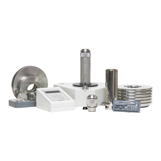
1. INTRODUCTION PRODUCT OVERVIEW PG7000 Piston Gauges are reference level pressure standards that operate on the piston gauge principle. Pressure is defined by balancing it against the force exerted by a known mass accelerated by gravity on the effective area of a piston-cylinder. A PG7000 piston gauge consists of the PG7000 Platform, one or several piston-cylinder modules and a mass set. -
Page 12: Specifications
PG7000™ OPERATION AND MAINTENANCE MANUAL SPECIFICATIONS 1.2.1 GENERAL SPECIFICATIONS Power Requirements 85 to 264 VAC, 50/60 Hz, 22 VA max. consumption. 15 to 35 °C Operating Temperature Range Weight Instrument platform with no mass loaded. PG7102 13 kg (29 lb) PG7202 13 kg (29 lb) PG7302... -
Page 13: Embedded Features
1. INTRODUCTION Pressure Connections PG7102 Test port: DH200 PG7202 Test port: DH500 Drain port: DH500 PG7302 Test port: DH500 PG7601 Test port: DH200 Bell Jar Vent Port: DH200 Vacuum Reference Pump Down Port: KF25 DH200 and DH500 are gland and collar type fittings for 1/4 in. -
Page 14: Ambient And Instrument Condition Measurements
PG7000™ OPERATION AND MAINTENANCE MANUAL 1.2.1.2 AMBIENT AND INSTRUMENT CONDITION MEASUREMENTS Temperature Ambient Piston Cylinder Module Range 0 to 40 0 to 40 0.01 Resolution ± 1 ± 0.1 Measurement Uncertainty Barometric Pressure with Internal Sensor Range 70 to 110 kPa Resolution 10 Pa ±... -
Page 15: Piston-Cylinder Modules
1. INTRODUCTION 1.2.2 PISTON-CYLINDER MODULES All piston-cylinders are integrated modules including mounting hardware delivered in individual shipping and storage bullet cases. 1.2.2.1 PC-7100/7600 Gas operated, gas lubricated piston-cylinder characteristics. PC-7100/7600-10 Operation Gas operated, gas lubricated Piston Material Ceramic (tungsten carbide available, higher mass) Cylinder Material Tungsten carbide Nominal Diameter... - Page 16 PG7000™ OPERATION AND MAINTENANCE MANUAL 1.2.2.2 PC-7200 Gas operated, liquid lubricated piston-cylinder module characteristics. Though not recommended for day to day operation, PC-7200 modules can also be filled completely with oil and operated with oil as the test medium (see Section 2.3.3). PC-7200-100 Operation Gas operated, liquid lubricated...
- Page 17 1. INTRODUCTION 1.2.2.3 PC-7300 Oil operated, oil lubricated piston-cylinder module characteristics. PC-7300 modules PC-7300-1, -2 and -5 may also be used in a PG7202 platform. PC-7300-100 Operation Oil operated, oil lubricated Piston and Cylinder Material Tungsten carbide Nominal Diameter 11.2 mm Nominal Area 98.1 mm Mounting System...
-
Page 18: Mass Sets
PG7000™ OPERATION AND MAINTENANCE MANUAL 1.2.3 MASS SETS All masses are delivered in molded, reusable, transit cases with custom inserts. Masses > 50g Material 304L non-magnetic stainless steel Finish Electropolished ± 20 ppm of nominal value Adjustment Tolerance ± 5 ppm or 1 mg, whichever is greater Uncertainty of Measured Values Masses <... -
Page 19: M A I N T E N A N C E , A D J U S T M E N T S A N D C A L I B R A T I O
1. INTRODUCTION 1.2.4.2 PC-7200 For uncertainty in piston-cylinder effective area and typical measurement uncertainty in pressure defined by the piston gauge, see the piston-cylinder calibration report and DHI Technical Note 7920TN01. PC-7200-100 Sensitivity 2 Pa + 1 ppm ± 5 ppm Reproducibility Typical Drop Rate (50 kg) 0.10 mm/min... - Page 20 PG7000™ OPERATION AND MAINTENANCE MANUAL 1.2.4.3 PC-7300 For uncertainty in piston-cylinder effective area and typical measurement uncertainty in pressure defined by the piston gauge, see the piston-cylinder calibration report and DHI Technical Note 7920TN01. PC-7300-100 Sensitivity 2 Pa + 1 ppm ±...
-
Page 21: Terminal And Platform Front And Rear Panels
1. INTRODUCTION TERMINAL AND PLATFORM FRONT AND REAR PANELS 1.3.1 TERMINAL FRONT AND REAR PANELS 1.3.1.1 PG TERMINAL FRONT PANEL The front panel assembly provides a 2 x 20 vacuum fluorescent display and a 4 x 4 membrane keypad for local user interface. The terminal front panel assembly is the same for all PG7000 models (i.e., PG7102, PG7202, PG7302, PG7601). -
Page 22: Pg Terminal Rear Panel
PG7000™ OPERATION AND MAINTENANCE MANUAL 1.3.1.2 PG TERMINAL REAR PANEL The rear panel assembly provides the communications connection to the PG7000 Platform and the power connection module. The terminal rear panel assembly is the same for all PG7000 models. Power Switch Fuse (25-pin) Power Receptacle... -
Page 23: I N S T A L L A T I O
2. INSTALLATION UNPACKING AND INSPECTION 2.1.1 REMOVING FROM PACKAGING A typical PG7000 system includes the PG7000 Platform (see Section 2.1.1.1), a mass set, (see Section 2.1.1.2), one or more piston-cylinder modules (see Section 2.1.1.3) and other accessories (see the accessory Operation and Maintenance Manual or Instruction Sheet). 2.1.1.1 PLATFORM The mass loading bell is a metrological element that is part of the mass set. -
Page 24: Mass Set
PG7000™ OPERATION AND MAINTENANCE MANUAL 2.1.1.2 MASS SET The stability over time of PG7000 pressure measurements is a function of the stability of the masses loaded on the piston. Precautions should be taken in handling the masses to minimize influences that may change their mass. -
Page 25: Table 1. Pg7102 Parts List
2. INSTALLATION Table 1. PG7102 Parts List PG7102 PG7102 PG7102 PG7102 P/N 401141 P/N 401141-CE P/N 401140 P/N 401140-CE DESCRIPTION MOTORIZED MOTORIZED NON-MOTORIZED NON-MOTORIZED ROTATION ROTATION ROTATION ROTATION NON-CE NON-CE Platform 401294 401294-CE 401293 401293-CE Mass Bell 401132 Bell Jar and Seal Terminal 401284 PG Terminal to Platform Cable... -
Page 26: Table 2. Pg7202 Parts List
PG7000™ OPERATION AND MAINTENANCE MANUAL Table 2. PG7202 Parts List PG7202 PG7202 PG7202 PG7202 #401722 #401722-CE #401721 #401721-CE DESCRIPTION MOTORIZED MOTORIZED NON-MOTORIZED NON-MOTORIZED ROTATION ROTATION ROTATION ROTATION NON-CE NON-CE Platform 401725 401725-CE 401724 401724-CE Mass Bell 401132 Bell Jar and Seal Terminal 401284 PG Terminal to Platform Cable... -
Page 27: Table 3. Pg7302 Parts List
2. INSTALLATION Table 3. PG7302 Parts List PG7302 PG7302 PG7302 PG7302 P/N 401298 P/N 401298-CE P/N 401297 P/N 401297-CE DESCRIPTION MOTORIZED NON-MOTORIZED NON-MOTORIZED MOTORIZED ROTATION ROTATION ROTATION ROTATION NON-CE NON-CE Platform 401292 401292-CE 401291 401291-CE Mass Bell 401132 Bell Jar and Seal Terminal 401284 PG Terminal to Platform Cable... -
Page 28: Table 4. Pg7601 Parts List
PG7000™ OPERATION AND MAINTENANCE MANUAL Table 4. PG7601 Parts List PG7601 PG7601 P/N 400480 P/N 400480-CE DESCRIPTION MOTORIZED MOTORIZED ROTATION ROTATION NON-CE Platform 401290 401290-CE Mass Bell 400578 Bell Jar and Seal 122106 and 101546 Terminal 401284 PG Terminal to Platform Cable Non-CE (DB25M -DB25F, 102227 ≈... -
Page 29: Mass Set
2. INSTALLATION 2.1.2.2 MASS SET PG7000 mass sets are composed of different combinations of individual masses and accessories depending on the specific mass set ordered (see Tables 5, 6, 7). Table 5. Mass Parts List (excluding 80 and 100 kg) DESCRIPTION PART NO. -
Page 30: Table 7. Mass Set Definitions
PG7000™ OPERATION AND MAINTENANCE MANUAL Table 7. Mass Set Definitions MASS SET COMPOSITION NOMINAL DESIGNATION PART # TOTAL TRIM SET MAKE-UP MASS (KG) 50 TO 0.1 G MASS (KG) MS-7001-35 401425 1 (4.5) MS-7002-35 401426 1 (4) MS-7002-40 401522 1 (4) MS-7002-45 401496 1 (4) -
Page 31: Piston-Cylinder Module(S)
2. INSTALLATION 2.1.2.3 PISTON-CYLINDER MODULE(S) Table 9. PC-7100/7600 Piston-Cylinder Modules Parts List 10 kPa 10 kPa 50 kPa 200 kPa PC-7100/7600-10 PC-7100/7600-10 TC PC-7100/7600-50 PC-7100/7600-200 Piston-Cylinder Kit 401561 401562 401563 401564 Piston-Cylinder Module 400580 401418 401332 401021 Hermetic PVC Bullet 401642 401642 401642... -
Page 32: Site Requirements
PG7000™ OPERATION AND MAINTENANCE MANUAL SITE REQUIREMENTS The exact PG7000 system installation is affected by the elements other than the PG7000 Platform that make up the PG7000 system. When selecting and preparing a site to set up the PG7000 system, the following should be considered: •... -
Page 33: Setup
2. INSTALLATION SETUP 2.3.1 PREPARING FOR OPERATION Before setting up the PG7000 system, see Section 2.2 for information on site requirements. To prepare PG7000 for check out and operation: Set up the PG7000 Platform (see Section 2.3.1.1). Make the system pressure interconnections (see Section 2.3.1.2). Set up the mass set (see Section 2.3.1.3). -
Page 34: System Pressure Interconnections
PG7000™ OPERATION AND MAINTENANCE MANUAL 2.3.1.2 SYSTEM PRESSURE INTERCONNECTIONS Interconnect the PG7000 Platform, pressure generation/control components and a test connection. The pressure connection on the PG7000 TEST port is: • PG7102/PG7601: DH200 (DH200 is equivalent to AE SF250C,HIP LF4, etc.). Adapters to convert the DH200 connection to 1/4 in. -
Page 35: Installing A Piston-Cylinder Module Into The Platform
2. INSTALLATION To install the masses on the mass loading tray, proceed as follows: Open the shipping cases. Install the main masses: The main masses (a series of 10 kg masses if the mass set is > 55 kg, a series of 5 kg masses if the mass set is < 60 kg) are installed horizontally aligned on the mass loading spindle. -
Page 36: Figure 4. Piston-Cylinder Module Installation
PG7000™ OPERATION AND MAINTENANCE MANUAL Place the piston-cylinder module in the PG7000 Platform mounting post. Place the piston-cylinder module (thread down) into the PG7000 Platform mounting post (see Figure 4 below). If installing the piston-cylinder module into a PG7302 or a PG7202 to be operated with oil, first use the oil generation control component to fill the counterbore in the mounting post with oil until it just starts to overflow. -
Page 37: Switching A Pg7202 Between Gas Operation And Oil Operation
2. INSTALLATION 2.3.3 SWITCHING A PG7202 BETWEEN GAS OPERATION AND OIL OPERATION PG7202 can be operated with gas as the pressurized medium using PC-7200 gas operated, liquid lubricated modules or with oil as the pressurized medium using oil operated PC-7300 modules. -
Page 38: Power Up And Verification
PG7000™ OPERATION AND MAINTENANCE MANUAL Switching a PG7202 from oil to gas operation Remove the piston-cylinder module. Disinstall the PC-7300 oil operated piston-cylinder module for the PG7202 platform. Disconnect the oil generation/control system from the DRAIN port. Place a paper towel under the DRAIN port and disconnect the tube to the oil generation/control system. -
Page 39: Set Local Gravity Value
2. INSTALLATION <1PC/MS> (see Section 3.11.1). Compare all the information contained in the PG7000 piston-cylinder, mass set and mass loading bell files to the information on the current piston-cylinder, mass set and mass loading bell calibration reports. 2.4.3 SET LOCAL GRAVITY VALUE PG7000 uses the value of local acceleration due to gravity (gl) in its calculation of the reference pressure it defines (see Section 3.1). -
Page 40: Apply Pressure To The Piston-Cylinder Module
PG7000™ OPERATION AND MAINTENANCE MANUAL 2.4.6 APPLY PRESSURE TO THE PISTON-CYLINDER MODULE This section assumes that the PG7000 system has already been set up, including pressure interconnection (see Section 2.3). Before applying pressure to the PG7000 system, be sure that all pressure vessels and connections are rated for the pressure levels that will be applied and that all connections have been properly tightened. -
Page 41: Check Proper Operation Of Piston Behavior Measurements
2. INSTALLATION 2.4.8 CHECK PROPER OPERATION OF PISTON BEHAVIOR MEASUREMENTS Float the piston and rotate it (see Sections 2.4.6 and 2.4.7). Press [SYSTEM] once to reach the first SYSTEM run screen. Verify that the piston position, piston fall/rise rate, piston rotation rate and piston rotation decay rate are indicating correctly (see Section 3.9.5). -
Page 42: Check Automated Pressure Generation (If Present)
PG7000™ OPERATION AND MAINTENANCE MANUAL 2.4.9 CHECK AUTOMATED PRESSURE GENERATION (IF PRESENT) Before applying pressure to the PG7000 system, be sure that all pressure vessels and connections are rated for the pressure levels that will be applied and that all connections have been properly tightened. -
Page 43: Short Term Storage
2. INSTALLATION SHORT TERM STORAGE The following is recommended for short term storage of PG7000. Remove all masses from the PG7000 Platform. Vent all circuits to atmosphere. Turn OFF power using the power switch on the rear of the PG7000 Terminal. Cover the PG7000 Platform and mass set with their dust covers. - Page 44 PG7000™ OPERATION AND MAINTENANCE MANUAL © 1998-2002 DH Instruments, Inc. Page 34...
-
Page 45: G E N E R A L O P E R A T I O
3. GENERAL OPERATION FUNDAMENTAL OPERATING PRINCIPLES PG7000s operate on the principle of the piston gauge in which pressure is defined by balancing it against a known force on a known area (see Figure 5). The known area is defined by a vertically mounted piston rotating in a cylinder and the known force is applied to the piston by loading it with known mass subjected to acceleration due to gravity. -
Page 46: Gas Operated, Liquid Lubricated Piston-Cylinder Operating Principle
PG7000™ OPERATION AND MAINTENANCE MANUAL Once PG7000 has been set up, it is used in day-to-day work either to define pressures applied to a device or system under test or to measure a stable pressure. To interface with the PG terminal, the operator: Selects the appropriate piston-cylinder to cover the pressure range (see Section 3.11.1.5). -
Page 47: Keypad Layout And Protocol
3. GENERAL OPERATION Figure 6. Gas Operated, Liquid Lubricated Piston-Cylinder (PC-7200) Operating Principle KEYPAD LAYOUT AND PROTOCOL PG7000 has a 4 x 4 keypad for local operator access to direct functions, function menus and for data entry. The Function/Data keys allow very commonly used functions to be accessed directly from the main run screen by a single keystroke. -
Page 48: Sounds
PG7000™ OPERATION AND MAINTENANCE MANUAL Pressing the [ESCAPE] key generally allows movement back in the menu tree and/or causes execution to cease or suspend without changes being implemented. Pressing [ESCAPE] repeatedly eventually returns to the main run screen. From the main run screen, pressing [ESCAPE] allows momentary viewing of the PG7000 identification screen. -
Page 49: Piston Position Ready/Not Ready
3. GENERAL OPERATION 3.4.1 PISTON POSITION READY/NOT READY The piston position Ready/Not Ready character indicates Ready or Not Ready based on the position of the piston in its vertical stroke (see Section 3.5) and an automated measure generation status (see Section 3.9.9). This ensures that pressure definitions will be made with the piston not more than a certain distance from mid-float position and that measurements will not be made while pressure is being adjusted. -
Page 50: Vacuum Reference Ready/Not Ready (Pg7601 Only)
PG7000™ OPERATION AND MAINTENANCE MANUAL Piston rotation rate Ready/Not Ready character indications include: <*> Rotation rate Ready: Rotation rate is within the rotation rate limits specified in the current piston-cylinder module file) (see Section 3.11.1.1). < < > Rotation rate Not Ready, low: Rotation rate is less than the rotation rate limits specified in the current piston-cylinder module file) (see Section 3.11.1.1) or motorized rotation system is currently engaged. -
Page 51: Piston Position
3. GENERAL OPERATION PISTON POSITION When operating a PG7000 piston gauge, reference pressure values are defined by loading known mass values on the piston and adjusting the pressure to float the piston. Piston position is measured and displayed real time on the MAIN run screen (see Section 3.7) and in the first SYSTEM run screen (see Section 3.9.5). -
Page 52: Mass Loading Protocol
PG7000™ OPERATION AND MAINTENANCE MANUAL MASS LOADING PROTOCOL PURPOSE To provide the operator with mass loading instructions and allow mass entry in convenient nominal values which PG7000 can accurately convert to measured mass values to determine the actual mass load. PRINCIPLE All PG7000 masses of 0.1 kg and above, including those in the mass set, the mass loading bell and the piston assembly, are adjusted so that their true mass is within ±... - Page 53 3. GENERAL OPERATION PG7000 mass loading entries and instructions are always formatted: kkk.k kg and nn.nn g • The mass set being used must be selected as the active mass set (see Section 3.11.1.10) and must be properly set up prior to use (see Section 3.11.1.6). •...
- Page 54 PG7000™ OPERATION AND MAINTENANCE MANUAL EXAMPLES: Mass Loading • • Mass loading instruction using PG7302 and an Mass loading instruction using a PG7601 and a 35 kg mass set: 80 kg mass set: 12.3 kg and 32.33 g 77.6 kg and 10.45 g Load: Load: piston (0.2 kg)
-
Page 55: Main Run Screen
3. GENERAL OPERATION MAIN RUN SCREEN The PG7000 main run screen is its home display that is reached upon powering up and from which other functions and menus are accessed. It is the top level of all menu structures. The main run screen is where PG7000 is left in normal operation. It displays the pressure defined by PG7000, Ready/Not Ready condition and a variety of other information. -
Page 56: General Function/Menu Flow Chart
3. GENERAL OPERATION GENERAL FUNCTION/MENU FLOW CHART Local operator interface with PG7000 is provided by PG Terminal keypad and display. Normal PG7000 operation is organized around run screens from which functions and menus are accessed. The run screens include: • MAIN run screen: Displays Ready/Not Ready, defined pressure, piston position and mass load. •... -
Page 57: Direct Function Keys
3. GENERAL OPERATION DIRECT FUNCTION KEYS 3.9.1 DIRECT FUNCTION KEYS SUMMARY Local operator interface with PG7000 is provided by PG Terminal keypad and display. To minimize the use of multi-layered menu structures, the keypad’s numerical keys also provide direct access to the most commonly used functions. The function accessed is labeled on the bottom half of the each key. -
Page 58: [P-C]
PG7000™ OPERATION AND MAINTENANCE MANUAL 3.9.2 [P-C] PURPOSE To view and/or change the active piston-cylinder module. In most cases, changing the piston-cylinder module is equivalent to changing the range. [P-C] is for selecting the active piston-cylinder module only. Piston-cylinder modules can be added and deleted and their characteristics can be edited by pressing [SPECIAL] and selecting <1PC/MS>... -
Page 59: Unit]
3. GENERAL OPERATION Pressing [P-C] again or [+/-] causes the screen to step through the other available piston- cylinder modules in the sequence that they were added. Nominal pressure to mass conversion coefficient of the piston-cylinder module. This value is calculated from the effective area of the piston-cylinder and is always in kPa (if <... - Page 60 PG7000™ OPERATION AND MAINTENANCE MANUAL OPERATION To change the pressure unit of measure, press the 1kPa 2MPa [UNIT] function key from any run screen. The display 4bar 5psi 6kcm2 is (default units depend on model): The cursor is on the number corresponding to the active unit. To change the pressure unit, select the desired unit.
-
Page 61: Customizing Pressure Units Available Under The Unit Function
3. GENERAL OPERATION 3.9.3.1 CUSTOMIZING PRESSURE UNITS AVAILABLE UNDER THE UNIT FUNCTION PURPOSE To customize the selection of pressure units that are available for selection from the [UNIT] function key. PRINCIPLE The UNIT function provides a choice of different pressure units of measure depending on the PG7000 model. -
Page 62: Mode]
PG7000™ OPERATION AND MAINTENANCE MANUAL If <4user> was selected, the user unit must be defined. The display is: Define user unit: Entry field. 1.000000 Units/Pa Enter the number of user units per Pascal [Pa] in the entry field. Pressing [ENTER] defines the user unit and returns to the <Set up unit #>... - Page 63 3. GENERAL OPERATION This mode is more convenient and less costly than absolute by vacuum since no vacuum reference needs to be established. However, it does not allow absolute pressures under atmosphere and the minimum absolute pressure is atmospheric pressure plus the pressure resulting from loading the combined mass of the piston and the bell on the piston-cylinder effective area.
-
Page 64: Differential Measurement Mode (Pg7601 Only)
PG7000™ OPERATION AND MAINTENANCE MANUAL 3.9.4.1 DIFFERENTIAL MEASUREMENT MODE (PG7601 ONLY) PURPOSE To define gauge pressures near and under atmospheric pressure that cannot be covered in conventional gauge mode; to define pressures at a static pressure near atmospheric pressure but other than atmospheric pressure. Differential mode operation is only supported by PG7601. -
Page 65: Figure 10. Differential Mode Controller Schematic
3. GENERAL OPERATION For differential mode operation, the PG7000 Differential Mode Interconnections Kit should be used to provide the DUT high and low test connections and support the RPM offsetting procedure (see Figure 9 and Section 3.9.4.1). A precision Reference Pressure Monitor, such as a DHI RPM, must be selected for the AtmP source in SETUP (see Section 3.10, 3.11.5.4). - Page 66 PG7000™ OPERATION AND MAINTENANCE MANUAL OPERATION To select differential mode operation and access differential mode functions press [MODE] and select <4dif>. Differential mode operation includes: • Selecting differential mode, setting static pressure and finding the RPM offset (see Section 3.9.4.1, Selecting Differential Mode, Setting Static Pressure, Finding RPM Offset (<1run>).
-
Page 67: Table 14. Valve Settings For Setting Differential Mode Static Pressure
3. GENERAL OPERATION Table 14. Valve Settings for Setting Differential Mode Static Pressure VALVE VALVE SETTING Control Selection Static P PG Shutoff Closed Test Bypass Open Static P Selection static pressure atmospheric pressure VENT or OFF With the Differential Mode Controller valves (see Figure 9) set as indicated in Table 14, use the systems’... - Page 68 PG7000™ OPERATION AND MAINTENANCE MANUAL Once the valves have been properly set and the mass has been loaded, install the bell jar and establish vacuum under the bell jar. Then press [ENTER]. The display is: Current pressure reading of the RPM in the current units of measure.
-
Page 69: Table 16. Valve Settings For Operating In Differential Mode
3. GENERAL OPERATION Operating in Differential Mode Differential mode is often used to calibrate DUTs with very low differential pressure ranges. These can easily be overpressured and damaged by inadvertently applying excessive pressure to one port. OPEN the MPC1-D BYPASS valve to zero the differential across the DUT when there is a risk of overpressure. - Page 70 PG7000™ OPERATION AND MAINTENANCE MANUAL Typical Differential Mode Operational Sequence See Figure 9 for a schematic of the Differential Mode Controller and its valves. Set RPM offset at desired static pressure (see Section 3.9.4.1, Selecting Differential Mode, Setting Static Pressure, Finding RPM Offset (<1run>)). Select pressure to mass or mass to pressure mode (see Section 3.9.12).
-
Page 71: High Line Differential Measurement Mode (Pg7102 And Pg7202 Only)
3. GENERAL OPERATION Setting Zero Differential Pressure See Figure 9 for a schematic of the Differential Mode Controller and its valves. Zero differential pressure can be set by PG7000 or simply by setting the Differential Mode Controller TEST BYPASS valve to the OPEN position which connects the HIGH and LOW TEST ports together. - Page 72 PG7000™ OPERATION AND MAINTENANCE MANUAL PRINCIPLE DHI Technical Note 0080TN03 provides more detailed information on high line differential mode principles including a complete uncertainty analysis. Consult DHI or visit our website, www.dhinstruments.com to obtain a copy. High line differential mode is designed to allow a PG7102 or PG7202 and a second gas operated PG7000 to be used together to define differential pressures relative to line pressures significantly above atmospheric pressure.
- Page 73 3. GENERAL OPERATION The tare and reference PG7000s must have nominally identical piston-cylinders. The two PG7000s operate together with the reference acting as “master” and the tare as “slave”. For communications between the two to occur, COM2 of the reference must be connected to COM1 of the tare with a valid RS232 cable and proper settings must be made on both interfaces (see Section 3.11.5.1).
-
Page 74: Figure 11. High Line Differential Mode Schematic
PG7000™ OPERATION AND MAINTENANCE MANUAL Tare PG7000 (PG7102, PG7202, or PG7601) MPC1-D or other Hi Variable Volume (Hi VV) Differential Device Under Test (DUT MPC1-D or other VENT Valve Reference PG7000 (PG7102 or PG7202) MPC1-D or other HI/LO BYPASS Valve MPC1-D or other INLET Valve MPC1-D or other Lo Variable Volume (Lo VV) Figure 11. - Page 75 3. GENERAL OPERATION • Setting differential pressures at a high line pressure (see Section 3.9.4.2, Setting Differential Pressures at a High Line Pressure). • Viewing current line pressure and natural fall rates for the line pressure (see Section 3.9.4.2, Viewing Line Pressure, Starting Piston-Cylinder Temperatures and Natural Piston Fall Rates ([MODE], <3HLdif>, <2view>).
- Page 76 PG7000™ OPERATION AND MAINTENANCE MANUAL While in high line differential pressure mode, the tare PG Terminal keypad is inactive. After high line differential mode is initialized, the display of the reference PG7000 is: Current (last set) value of line pressure in current Line P: 1000 psi pressure unit of measure.
- Page 77 3. GENERAL OPERATION Values of line pressure are always entered and displayed in gauge mode (i.e., relative to atmospheric pressure). Line pressure mass loading instructions are always given with 0.1 kg resolution. The minimum line pressure is the pressure resulting when the mass of the piston + mass bell is loaded. Enter the desired line pressure value.
- Page 78 PG7000™ OPERATION AND MAINTENANCE MANUAL Indication of tare piston position. T +1.0 mm R +1.0 Indication of reference piston position. ↓ Finding rates 30 second count down. Wait for the 30 second timer to count down while the measurements are made. Be sure not to interfere with the free movement of the piston-cylinders during the countdown.
- Page 79 3. GENERAL OPERATION Crossfloat the two pistons to find equilibrium by making mass adjustments on the tare piston. Finding equilibrium is an iterative process which is assisted by PG7000. Pressing [ENTER] starts an automated fall rate measurement sequence that measures the fall rates more precisely than the real time indication. Following a 30 second countdown or when one of the pistons has moved more than 1 mm, PG7000 displays the measured “equilibrium fall rate”...
- Page 80 PG7000™ OPERATION AND MAINTENANCE MANUAL Evaluate the quality of the equilibrium. Check the value of the “equilibrium fall rate”. Consider that the closer the rate is to zero, the better the equilibrium; consider that the suggested mass change on the tare piston times the mass to pressure conversion coefficient of the piston approximates the pressure value of the defect in the equilibrium.
- Page 81 3. GENERAL OPERATION Before operating in differential mode the line pressure must be set (see Section 3.9.4.2, Setting a Line Pressure ([MODE], <3HLdif>, <1run>, <2yes>)). Once the line pressure is set, from a practical standpoint, operating in high line differential mode is very similar to operating in gauge mode (see Section 3.9.11). All operator interaction is with the PG Terminal of the reference PG7102 or PG7202.
- Page 82 PG7000™ OPERATION AND MAINTENANCE MANUAL Typical Sequence to Set Differential Pressures at a High Line Pressure Set the desired line pressure (see Section 3.9.4.2, Setting a Line Pressure ([MODE], <3HLdif>, <1run>, <2yes>)). Select pressure to mass or mass to pressure mode (see Section 3.9.12). If desired, read DUT output at zero differential pressure with BYPASS valve OPEN.
-
Page 83: System]
3. GENERAL OPERATION Press [ENTER] to continue to the next view screen or [ESCAPE] to go to the previous screen. The next view screen is: Average fall rate of the tare piston recorded at the last line pressure. T-0.91 mm/min R-1.10 Average fall rate of the reference piston recorded at ∆... -
Page 84: First System Run Screen
PG7000™ OPERATION AND MAINTENANCE MANUAL 3.9.5.1 FIRST SYSTEM RUN SCREEN OPERATION The first SYSTEM run screen provides real time display of piston rotation rate and decay in piston rotation rate, piston position and piston fall rate. To access the first SYSTEM run screen, press [SYSTEM] from any other run screen. -
Page 85: Second System Run Screen
3. GENERAL OPERATION 3.9.5.2 SECOND SYSTEM RUN SCREEN OPERATION The second SYSTEM run screen displays the values of piston-cylinder temperature and temperature rate of change currently used by PG7000. PG7601 also displays reference vacuum and vacuum rate of change. If internal measurement is specified for these values in SETUP (see Section 3.10), the second SYSTEM run screen provides a real time display of the values measured. -
Page 86: Ambient]
PG7000™ OPERATION AND MAINTENANCE MANUAL 3.9.6 [AMBIENT] PURPOSE Access the AMBIENT run screen which displays the current ambient condition values being used by PG7000 for calculations of reference pressures. PRINCIPLE PG7000 uses ambient condition values to calculate the reference pressures that it defines (see Section 0). -
Page 87: Head]
3. GENERAL OPERATION feet (ft). 3.9.7 [HEAD] PURPOSE To cause a pressure value, representing the fluid head resulting from a difference in height, to be added to the pressure defined by PG7000 at its reference level. To set the height of the DUT head. - Page 88 PG7000™ OPERATION AND MAINTENANCE MANUAL OPERATION To access the HEAD function, press [HEAD]. The display is: Edit DUT head height: Test fluid currently specified for the head correction. 95 cm Entry field for head height (1 to 999 cm or in.). Entering a value of zero turns the HEAD function OFF.
-
Page 89: Rotate] (Optional On Pg7102, Pg7202 And
3. GENERAL OPERATION 3.9.8 [ROTATE] (OPTIONAL ON PG7102, PG7202 AND PG7302) PURPOSE To turn automatic control of motorized piston rotation ON and OFF. See Section 3.9.13 for information on manual control of motorized piston rotation. PRINCIPLE PG7000s offer a motorized piston rotation system. Motorized rotation is standard on PG7601 and optional on PG7102, PG7202 and PG7302. -
Page 90: Gen] (Optional)
PG7000™ OPERATION AND MAINTENANCE MANUAL Automatic motorized piston rotation is dependent on PG7000’s measurements of piston position and rotation rate. These measurements are only available when the mass loading bell is installed on the piston. Automatic piston rotation is suspended when the current PG7000 mass load does not include the mass loading bell. -
Page 91: Res]
3. GENERAL OPERATION is displayed momentarily. Correct the communications error with the pressure generation/control component and try again. If automated pressure generation/control is OFF, when [GEN] is pressed and PG7000 is able to establish communications with a valid automated pressure generation/control component, <Turning ON automated generation>... -
Page 92: Enter] From Run Screen
PG7000™ OPERATION AND MAINTENANCE MANUAL will be a value near 10 kg such as 9.99731 kg. This value is difficult to load as it requires relatively complex mass accounting and the manipulation of very small sub-gram masses. To avoid handling a difficult odd mass value, one might instead decide to load 10 kg and use whatever pressure results as the reference pressure. -
Page 93: Enter] In Pressure To Mass Mode
3. GENERAL OPERATION OPERATION To access the pressure or mass entry screen, press [ENTER] from any run screen. The sequence after [ENTER] has been pressed varies between mass to pressure and pressure to mass mode. The mode is selected by pressing [P M] (see Section 3.9.12). - Page 94 PG7000™ OPERATION AND MAINTENANCE MANUAL The display is: Target pressure: Current measurement mode (see Section 3.9.4). 100.0000 kPa a Current pressure unit of measure (see Section 3.9.3). Entry field for the target value of pressure to be set. Use the numerical keys and editing keys to enter the target pressure value desired. Press [ENTER] to process the target pressure value.
-
Page 95: Ent] In Mass To Pressure Mode
3. GENERAL OPERATION 3.9.11.2 [ENT] IN MASS TO PRESSURE MODE PURPOSE To enter and execute a mass to pressure command in mass to pressure mode (see Section 3.9.12). OPERATION Put the PG7000 in mass to pressure operation mode (see Section 3.9.12), then press [ENTER] in any run screen. -
Page 96: Por M]
PG7000™ OPERATION AND MAINTENANCE MANUAL 3.9.12 PURPOSE To select between PG7000 pressure to mass or mass to pressure operation mode. PRINCIPLE Piston gauges are generally used either to define desired pressure set points (e.g., when applying reference pressures to a device to be calibrated) or to measure a static pressure (e.g., when performing a crossfloat intercomparison with another piston gauge). -
Page 97: Setup] Menu
3. GENERAL OPERATION OPERATION To momentarily engage the motorized piston rotation system, press [ ] from any run screen. If PG7000 is equipped with motorized rotation, the motorized rotation system engages and remains engaged until maximum rotation rate has been achieved or the key is released. -
Page 98: Table 17. Setup File Choices, Factory Preferred Choice And Normal Value
PG7000™ OPERATION AND MAINTENANCE MANUAL The SETUP function supports the following: • View SETUP files (see Section 3.10.2); • Create/edit SETUP files (see Section 3.10.3); • Select active SETUP file (see Section 3.10.1. Table 17. SETUP File Choices, Factory Preferred Choice and Normal Value FACTORY VARIABLE SOURCE... -
Page 99: 1Select
3. GENERAL OPERATION 3.10.1 <1SELECT> PURPOSE To change the active SETUP file number. Changing the current SETUP file will change the source and in some cases the values of the variables used by PG7000 in calculating defined pressure. SETUP files should be selected and changed only by qualified personnel. -
Page 100: 3Edit
PG7000™ OPERATION AND MAINTENANCE MANUAL View #02 latmP 2ambT Enter the desired SETUP file number and press [ENTER]. If a valid SETUP file number is entered, the 3%RH 4PCT 5g 6READY↓ display is: 7vac Select <1atmP> to view the atmospheric pressure variable source choice and current value. The value is displayed in the current pressure units (see Section 3.9.3). - Page 101 3. GENERAL OPERATION Enter the desired SETUP file number and press [ENTER]. Edit #02 latmP 2ambT If a valid SETUP file number is entered, the display is: 3%RH 4PCT 5g 6READY↓ 7vac Selecting an item leads to the variable source choices menu for that item. The cursor is on the source choice that is currently selected in that SETUP file number.
-
Page 102: Special] Menu
PG7000™ OPERATION AND MAINTENANCE MANUAL Select <5g> to specify the value of acceleration due to gravity that is used in calculating the force applied to the piston. Pressing <5g> offers the gravity variable source choices: Use the fixed value of local gravity stored under [SPECIAL], <6gl> (see Section 3.11.6). <1locall>: Use a fixed value of 9.806650 m/s <2normal>:... -
Page 103: 1Pc/Ms
3. GENERAL OPERATION <9reset>: Access and execute various reset options (see Section 3.11.9). OPERATION 1PC/MS 2presU 3head To access the SPECIAL menu, press [SPECIAL] from ↓ 4intern 5remote 6g1 the main run screen. This display is: 7cal 8level 9reset Select the desired function. See Sections 3.11.1 to 3.11.9 for detailed SPECIAL function descriptions. -
Page 104: Create Piston-Cylinder Module
PG7000™ OPERATION AND MAINTENANCE MANUAL OPERATION To access the piston-cylinder module, mass set and 1PC 2mass set mass loading bell information, press [SPECIAL] and 3mass bell select <1PC/MS>. The display is: Select the type of metrological element that you would like to view, edit, create or select. See Sections 3.11.1.1 to 3.11.1.7 for operation of specific piston-cylinder module, mass set and mass bell functions as follows: •... - Page 105 3. GENERAL OPERATION Setting up or editing a piston-cylinder module requires specifying, in sequential order, the following: Serial number (S/N) [nnnn]. Effective area (Ae) at 0 pressure and 20 °C [mm2]. Piston temperature coefficient [linear thermal expansivity/°C]. Cylinder temperature coefficient [linear thermal expansivity/°C]. Effective area pressure coefficient [change in Ae/MPa].
- Page 106 PG7000™ OPERATION AND MAINTENANCE MANUAL • Cylinder temperature coefficient: Edit the value of the cylinder material linear thermal expansivity. The value must be entered in terms of relative change per degree centigrade [nn x 10 /°C]. The 10 exponent is fixed. This value is reported in the calibration report for the piston-cylinder module.
-
Page 107: Edit Piston-Cylinder Module Information
3. GENERAL OPERATION After pressing [ENTER] to accept the edited Save PC S/N nnnn calibration report date the option to save the edited piston-cylinder module information is 1no 2yes presented. The display is: Select <2yes> to save the piston-cylinder module information under serial number nnnn and return to the <1PC/MS>... -
Page 108: Delete Piston-Cylinder Module
PG7000™ OPERATION AND MAINTENANCE MANUAL 3.11.1.4 DELETE PISTON-CYLINDER MODULE PURPOSE To delete a piston-cylinder module file so that it is no longer included in the piston-cylinder modules available for selection by pressing [P-C]. OPERATION Once a piston-cylinder module file has been deleted it cannot be recovered. To recreate it, the add piston-cylinder module function must be used (see Section 3.11.1.1) which requires entering all the piston-cylinder module information. - Page 109 3. GENERAL OPERATION PRINCIPLE The PG7000 add and edit mass set functions allow mass set composition and metrological variable values to be defined and stored. These values will be used by PG7000 when the mass set is made active to calculate nominal mass instructions and true mass loads.
- Page 110 PG7000™ OPERATION AND MAINTENANCE MANUAL Though the piston and the mass loading bell constitute part of the mass load, they are not included in the definition of a mass set. The piston-cylinder module is delivered separately and the mass bell is delivered with the PG7000 Platform, independent from the mass set.
- Page 111 3. GENERAL OPERATION Edit the calibration report number to the current Cal report date? calibration report number of the mass set that is 198001010 being added and press [ENTER]. The display is: Edit the calibration report date to the date of the current calibration report of the mass set that is being added (must use YYYYMMDD format) and press [ENTER].
-
Page 112: Edit Mass Set
PG7000™ OPERATION AND MAINTENANCE MANUAL Edit the number of masses in group to reflect the number of masses of that nominal value, in this case 5 kg, there are in the group and press [ENTER]. The display is: Sequential ID number of this specific mass within the 5.0 kg mass #1 mass group. -
Page 113: View Mass Set
3. GENERAL OPERATION 3.11.1.8 VIEW MASS SET PURPOSE To view information contained in an existing mass set file. OPERATION To view information contained in an existing mass set file press [SPECIAL] and select <1PC/MS>, <2mass set>, <1view>. The viewing function is identical to the add function (see Section 3.11.1.6). - Page 114 PG7000™ OPERATION AND MAINTENANCE MANUAL OPERATION Mass loading bell information is element specific metrological data. Uninformed or accidental altering of this information may lead to out of tolerance measurements. Mass loading bell information should only be edited by qualified personnel as part of the PG7000 calibration or recalibration process.
-
Page 115: Edit Mass Loading Bell Information
3. GENERAL OPERATION 3.11.1.12 EDIT MASS LOADING BELL INFORMATION PURPOSE To edit information contained in an existing mass loading bell file. Use this function to change mass loading bell data after a recalibration. PRINCIPLE/OPERATION Mass loading bell information is element specific metrological data. Uninformed or accidental altering of this information may lead to out of tolerance measurements. -
Page 116: Select Mass Loading Bell
PG7000™ OPERATION AND MAINTENANCE MANUAL 3.11.1.15 SELECT MASS LOADING BELL PURPOSE To select the mass loading bell that is active and used by PG7000 in its mass loading and defined pressure calculations. OPERATION To select the active mass loading bell set press [SPECIAL] and select <3mass bell>, <5select>. -
Page 117: 3Head>, <1Fluid
3. GENERAL OPERATION OPERATION Edit head: 1fluid To access various fluid HEAD correction functions press [SPECIAL], and select <3head>. The display is: 2unit 3atm 4piston • Select <1fluid> to change the DUT head fluid (see Section 3.11.3.1). • Select <2unit> to specify the DUT head height unit of measure (see Section 3.11.3.2). •... -
Page 118: 3Head>, <3Atm
PG7000™ OPERATION AND MAINTENANCE MANUAL 3.11.3.3 <3HEAD>, <3ATM> OPERATION To specify the ATM head height (see Section Edit ATM head unit: 3.11.3, PRINCIPLE), press [SPECIAL] and -10.00 cm select <3head>, <3atm>. The display is: Entering the ATM head returns to the previous run screen with the new height active. -
Page 119: 4Prefs
3. GENERAL OPERATION 3.11.4 <4PREFS> PURPOSE To access a menu of PG7000 internal operational preferences and functions. • Select <ScrSvr>. View and change the screen saver function (see Section 3.11.4.1). • Select <sounds>. View and change keypad press and piston position sound settings (see Section 3.11.4.2). -
Page 120: 4Prefs>, <3Time
PG7000™ OPERATION AND MAINTENANCE MANUAL Select <1keypad> to adjust keypad sounds. Select <2piston> to turn the position sounds ON or OFF. 3.11.4.3 <4PREFS>, <3TIME> PURPOSE To view and edit the PG7000 internal time and date settings. OPERATION To access the time function press [SPECIAL] Edit: 1time 2date and select <4prefs>, <3time>. -
Page 121: 5Remote
3. GENERAL OPERATION The ID can be viewed and edited but it cannot be cleared or reset by any reset functions (see Section 3.11.9). 3.11.5 <5REMOTE> PURPOSE To configure the PG7000 COM1, COM2, COM3 and IEEE-488 communication ports. To test COM1, COM2 and COM3 communications. -
Page 122: Ieee-488
PG7000™ OPERATION AND MAINTENANCE MANUAL The default COMx settings are 2400, E, 7,1, for all three <CR><LF> or <LF><CR> COM ports. PG7000 appends a carriage return (<CR>) and a line feed (<LF>) or <LF><CR> to all messages that are sent out of the COM1 port to the host. It looks for a carriage return to terminate incoming messages and ignores line feeds. -
Page 123: External Barometer (Rpm) Communications (Com2)
3. GENERAL OPERATION 3.11.5.4 EXTERNAL BAROMETER (RPM) COMMUNICATIONS (COM2) PURPOSE To set up communications with an external barometer from which PG7000 will read the value of atmospheric pressure used in its internal calculations. external device is also used for reading the static pressure when PG7601 is used in differential mode (see Section 3.9.4). - Page 124 PG7000™ OPERATION AND MAINTENANCE MANUAL Reply conv coef: After the string value has been entered the display is: 1.000000 Pa/unit <conv coef> is the conversion coefficient that PG7000 will use to convert readings from the external barometer to the pressure unit of measure Pascal [Pa].
-
Page 125: 6Gl
3. GENERAL OPERATION 3.11.6 <6gl> PURPOSE To view and set the value of local gravity used by PG7000 in reference pressure calculations (see Section 7.2) when gl is specified as the gravity value in SETTINGS (see Section 3.10). OPERATION Local gravity: To access the PG7000 local gravity value (gl), press [SPECIAL] and select <6gl>. -
Page 126: Security Levels
PG7000™ OPERATION AND MAINTENANCE MANUAL Access to changing security levels can be left open, or be protected by a password so that security levels can be used as a convenient way to avoid accidental changing of data or as a secured means of preventing tampering with PG7000 settings. 3.11.8.1 SECURITY LEVELS The security levels are structured to support typical operating environments as... -
Page 127: Table 19. Security Levels - Functions Not Executed Per Function/Level
3. GENERAL OPERATION Table 19. Security Levels - Functions NOT Executed Per Function/Level FUNCTION MEDIUM HIGH • [P-C] • [UNIT] • [MODE] • [SYSTEM] • [AMBIENT] • • [HEAD] • [ROTATE] • [GEN] • • [RES] (change setting) • • •... - Page 128 PG7000™ OPERATION AND MAINTENANCE MANUAL OPERATION PG7000 is delivered with NO active password so access to the User Level menu is open. The User Level is set to <1Low>. User Levels can be changed freely until a password has been created. Reset functions (see Section 3.11.9) do not affect the password setting.
-
Page 129: 9Reset
3. GENERAL OPERATION 3.11.9 <9RESET> PURPOSE To reset various PG7000 settings to default or factory values. PG7000 stores its user definable settings in non-volatile memory. The reset menu allows the user to selectively or completely reset these settings to factory defaults. Resets clear settings that the user may have made, and should be used only to restore the PG7000 to a known state. -
Page 130: 9Reset>, <2Units
PG7000™ OPERATION AND MAINTENANCE MANUAL 3.11.9.2 <9RESET>, <2UNITS> PURPOSE/OPERATION To access Reset - Units, press [SPECIAL] and select <1reset>, <2units>. Reset - Units clears and sets to default all unit of measure functions. This includes: • [UNIT] pressure unit of measure selections to defaults and active unit to #1 (see Section 3.9.3). -
Page 131: 9Reset>, <5Setups
3. GENERAL OPERATION Barometric Sensor Adder Multiplier Calibration Date 19980101 Humidity Sensor Adder Multiplier Calibration Date 19980101 Ambient Temperature Sensor Adder Multiplier Calibration Date 19980101 Piston-Cylinder Module Temperature Sensor 100.000 Ω Slope 0.3896 Calibration Date 19980101 Vacuum Gauge (PG7601 Only) Adder Multiplier Calibration Date... - Page 132 PG7000™ OPERATION AND MAINTENANCE MANUAL © 1998-2002 DH Instruments, Inc. Page 122...
-
Page 133: Overview
4. REMOTE OPERATION OVERVIEW Most of the PG7000 Terminal’s front panel functions can also be executed by commands from a remote computer. The host computer can communicate with PG7000 using the COM1 RS232 port or the IEEE-488 port located on the PG7000 Platform rear panel. The command syntax is the same for either port except when using the IEEE STD. -
Page 134: Com2 And Com3
PG7000™ OPERATION AND MAINTENANCE MANUAL Table 20. COM1 DB-9F Pin Designation IBM PC/XT DB-9F CONNECTIONS IBM PC/XT DB-9M to PG7000 DB9F CONNECTIONS DB-25M DB-9F DB-9M DB-9F 4.2.1.2 COM2 AND COM3 The PG7000 COM2 and COM3 RS232 interfaces are located on the PG7000 Platform rear panel. -
Page 135: Commands
4. REMOTE OPERATION COM1, COM2 and COM3 Address Terminating Characters <CR> and <LF> with EOI asserted with <LF> SH1, AH1, T4, L2, RL2, DC2 IEEE Local Functions Supported Parallel poll mode is not supported Physical Interface IEEE-488.2 with tri-state bus drivers To establish IEEE-488 communications the host computer must IEEE-488 have an IEEE-488 card and PG7000 must be correctly addressed. -
Page 136: Command Summary
PG7000™ OPERATION AND MAINTENANCE MANUAL 4.3.2 COMMAND SUMMARY Table 22. Command Summary COMMAND DESCRIPTION AMPHx(=) Set or read the source for ambient humidity AMBPx(=) Set or read the source for ambient pressure AMBTx(=) Set or read the source for ambient temperature Read back the current ambient conditions AROT(=) Set or read the current automated motorized rotation status... - Page 137 4. REMOTE OPERATION COMMAND DESCRIPTION PISTONVARx(=) Set or read additional piston variables PISTONx(=) Set or read the piston primary information PISTON(=) Set or read the piston in use PPC= Send a command to an external pressure generation/control component connected to COM3 PPOS Read the current piston position PRTAMB...
-
Page 138: Error Messages
PG7000™ OPERATION AND MAINTENANCE MANUAL 4.3.3 ERROR MESSAGES The PG7000 will always reply to a command. If the command is incorrect or contains invalid data, an error number will be returned in the form “ERR# n” where n is an integer number that represents a specific error. -
Page 139: Command Descriptions
4. REMOTE OPERATION 4.3.4 COMMAND DESCRIPTIONS Each command description gives the full syntax showing usage. Ranges of parameters or parameter types are indicated. There are two types of commands. The Common and Status Commands support IEEE STD 488.2, while the molbloc RFM commands access all other functions. 4.3.4.1 IEEE STD. - Page 140 PG7000™ OPERATION AND MAINTENANCE MANUAL ∗IDN? Purpose Identify the PG7000 model, and serial number. Syntax “∗IDN?” Remarks The identification reply is made up of the manufacturer, the model, the serial number and the software version. Each is separated by a comma. Query Reply The version string.
-
Page 141: Pg7000 Commands
4. REMOTE OPERATION ∗STB? Purpose Read the Status Byte Register. Syntax “∗STB?” Remarks The Status Byte Register reflects the general status of the PG. The ‘MSS’ bit state is represented by bit 6. Query Reply n (0 to 255) Example Command: “*STB?”... - Page 142 PG7000™ OPERATION AND MAINTENANCE MANUAL AMBPx(=) Purpose Set or read the source for the ambient pressure measurement. Also optionally sets the USER defined measurement. Syntax “AMBPx=source, meas” “AMBPx=source” “AMBPx” Default 70.000 kPaa if the source is DEFAULT Argument The setup number from 1 to 21. See the SETUP command. Setup 21 is reserved for remote communication use only.
- Page 143 4. REMOTE OPERATION Purpose To read all of the ambient conditions from the sources defined by the current setup. Syntax “AMB” Default Argument none Remarks PG7000 calculations use five ambient conditions to calculate the current pressure. The source of these ambient conditions is defined by the current setup (see the SETUP command).
- Page 144 PG7000™ OPERATION AND MAINTENANCE MANUAL BELLx(=) Purpose Read or set a mass loading bell’s information. Syntax “BELLx=Sn, Dens, Mass, Report#, CalDate, EditDate” “BELLx” Default Argument The mass bell number 1, 2, or 3 The mass bell serial number (4 digits max) Dens: The mass bell density Mass:...
- Page 145 4. REMOTE OPERATION COMx(=) Purpose To set or retrieve the configuration of the COM ports. Syntax “COMx=baud,parity,data,stop” “COMx” Default “COM1=2400,E,7,1” “COM2=2400,E,7,1” “COM3=2400,E,7,1” Argument “1” for COM1 port “2” for COM2 port “3” for COM3 port The arguments must be separated by commas. Remarks The available parameters are listed below.
- Page 146 PG7000™ OPERATION AND MAINTENANCE MANUAL DIFOFFSET (=) Purpose Set or read the differential offset value. Syntax “DIFOFFSET=offset, pressure” “DIFOFFSET” Default Offset: 0 Pa Pressure: 101325.0 Paa Argument Offset: “NEW” Saves the current calculation of RPM offset if PG7601 is currently in the offset determination mode, else set the differential offset value in Pa.
- Page 147 4. REMOTE OPERATION DUTHEIGHT(=) Purpose To set or read the height of an external Device Under Test (DUT) relative to the reference level on the PG7000 mounting post (DUT head). Syntax “DUTHEIGHT=height” “DUTHEIGHT” Default “ATMHEIGHT=0.00cm” Argument height: The position of the device under test relative to the PG7000 mounting post reference mark.
- Page 148 PG7000™ OPERATION AND MAINTENANCE MANUAL HLDLINEP Purpose Execute the functions needed to set a new line pressure in high line differential mode. Syntax “HLDLINEP” “HLDLINEP=LineP” “HLDLINEP=NEXT” “HLDLINEP=REPEAT” Remarks This command controls the new line pressure set sequence. It starts the sequence, increments through the sequence steps and completes the sequence (see Section 4.5).
- Page 149 4. REMOTE OPERATION HLDPPOS Purpose Get the piston positions of the reference and tare PG7000s in high line differential mode. Also returns the real time or average crossfloat fall rate difference when available. Syntax “HLDPPOS” Remarks This command can be used while generating the line pressure or during normal high line pressure operation.
- Page 150 PG7000™ OPERATION AND MAINTENANCE MANUAL LOCAL Purpose Place the device in the LOCAL mode. Syntax “LOCAL” Default Argument Remarks In LOCAL mode all front panel operations are available. The LOCAL command deactivates REMOTE mode. Example Typical command: “”LOCAL” Typical reply: “LOCAL”...
- Page 151 4. REMOTE OPERATION MASSSETx(=) Purpose Read and define the masses included in the mass sets. Syntax “MASSSETX” “MASSSET=nominal,true” “MASSSET” Default Argument The mass set number 1, 2, or 3. To “close” a mass set. nominal: The nominal mass value. true: The true mass value.
- Page 152 PG7000™ OPERATION AND MAINTENANCE MANUAL MEDIA(=) Purpose Read or set the PG7000 pressurized medium type for DUT head corrections. Syntax “MEDIA=mediaType” “MEDIA” Default “MEDIA=N2 Argument mediaType: “N2”, “He”, “Air”, “Oil”, “H2O” or user set density value. Remarks You must select one of five (5) available media for use with the PG, of specified a user defined density.
- Page 153 4. REMOTE OPERATION MROT(=) Purpose Read or set the manual motorized rotation status. Syntax “MROT=rotationStatus” “MROT” Default “MROT=0” Argument Rotation Status: Set to “1” to engage the rotation system of PG7000. “0” disengages the system. Remarks You may manually control the rotation of the PG7000 bell instead of using the auto rotate function (see the “AROT”...
- Page 154 PG7000™ OPERATION AND MAINTENANCE MANUAL OHMS Purpose Read the mounting post and the ambient PRT resistances. Syntax “OHMS” Default Argument Remarks The mounting post and ambient temperature are measured and used for internal calculations. This command always returns the last measured value using the internal PRTs.
- Page 155 4. REMOTE OPERATION PISTONRDYx(=) Purpose Read or set a piston-cylinder module’s rotation rate Ready/Not Ready criteria. Syntax “PISTONRDYx=MinRPM, MaxRPM “PISTONRDYx” Default Argument MinRPM: The minimum allowed rotation speed at which the measurement becomes Ready [rpm]. If autorotate is enabled, this is also the point at which the rotation system will engage.
- Page 156 PG7000™ OPERATION AND MAINTENANCE MANUAL PISTON(=) Purpose Read or set the current piston-cylinder module. Syntax “PISTON=n” “PISTON” Default Argument The piston-cylinder module number 1 through 17. Remarks You may define up to seventeen different piston-cylinder modules to use with PG7000 using the PISTONx and PISTONVARx commands.
- Page 157 4. REMOTE OPERATION PRTPC Purpose Set or read the mounting post PRT temperature sensor calibration data. Syntax “PRTPC=Sn, slope, zero, report number, cal date” “PRTPC” Default 1, 0.3896, 100.00, 1, 19880101 Argument The serial number from 0 to 9999 The PRT slope (Ohms/0 °C) slope: The PRT resistance at 0 °C zero:...
- Page 158 PG7000™ OPERATION AND MAINTENANCE MANUAL READYCK(=) Purpose To set or check the ready check flag, or, used to determine if a Not Ready OT READY condition has occurred. Syntax “READYCK=1” “READYCK” Default READYCK=0 Argument Remarks The internal ready check flag is cleared whenever PG7000 reaches a Not Ready (NR) condition.
- Page 159 4. REMOTE OPERATION SETUP(=) Purpose To change or read the current SETUP to be used. Syntax “SETUP=n” “SETUP” Default “SETUP=1” Argument Remarks There are 19 SETUP files that can be created by the user to allow quick change from one configuration to another. Each configuration can specify the source of the ambient measurements, the gravity, and the ready criteria.
- Page 160 PG7000™ OPERATION AND MAINTENANCE MANUAL UCOEF Purpose To read the conversion coefficient used to convert Pascal to the current pressure unit of measure. Syntax “UCOEF” Default Argument Remarks Use this command to read the pressure conversion coefficient used to convert pressure in Pascal to the displayed pressure units.
- Page 161 4. REMOTE OPERATION UNIT(=) Purpose Set or change the current pressure unit of measure and pressure measurement mode. Syntax “UNIT=xxxxx” “UNIT” Default “UNIT=MPa g” “UNIT=kPa g” Argument Remarks The units in which PG7000 interprets and executes commands can be changed. The available units are: psi g psi a...
-
Page 162: Status System
PG7000™ OPERATION AND MAINTENANCE MANUAL VAC(=) Purpose To set or read PG7000 reference mode. This command is only valid for PG7601. Syntax “VAC=n” “VAC” Default VAC=0 Argument n = 1: PG7000 is being operated with a bell jar and vacuum n = 0: PG7000 is being operated at atmospheric pressure Remarks... -
Page 163: Status Byte Register
4. REMOTE OPERATION 4.4.1.1 STATUS BYTE REGISTER PG7000 contains an 8 bit status byte register that reflects the general status of PG7000. Table 24. Status Byte Register OPER RQS/MSS ERROR (128) (64) (32) (16) This register is affected by the PG7000 reply output queue, the error queue, the Standard Event Status register, the Ready Event Status register, and the STATus subsystem. -
Page 164: Standard Event Register
PG7000™ OPERATION AND MAINTENANCE MANUAL • MSS: Master Summary Status (Bit 6) Indicates that an event or events occurred that caused PG7000 to request service from the Host, much like the RQS bit. Unlike the RQS bit, it is READ ONLY and can be only cleared when the event(s) that caused the service request are cleared. -
Page 165: High Line Differential Mode Programming Examples
4. REMOTE OPERATION • QYE: Query Error (Bit 2) Indicates that an error has occurred in the protocol for program message communications. This is typically caused by a program message being sent to PG7000 without reading a waiting reply. • RQC: Request Control (Bit 1) This bit is not supported as PG7000 cannot become the active... - Page 166 PG7000™ OPERATION AND MAINTENANCE MANUAL The status of the fall rate step can be monitored by sending the HLDLINEP command until the reply is no longer “BUSY1”. During this time, the reference and tare piston positions should also be monitored. So, while using HDLPPOS to monitor piston, occasionally send HLDLINEP looking for the response OK.
-
Page 167: Recommended Sequence For A Host Program To Remotely Enable High Line Differential Mode Using The Last Line Pressure Setting
4. REMOTE OPERATION Send: “HLDLINEP” (Check if the step is completed) Reply: “BUSY2” (Step is still busy, continue in this loop) Reply: “OK” (Step is still complete; go to next step) The results of the crossfloat fall rate measurement step can now be obtained: Send: “HLDXFLT”... - Page 168 PG7000™ OPERATION AND MAINTENANCE MANUAL © 1998-2002 DH Instruments, Inc. Page 158...
-
Page 169: Introduction
5. MAINTENANCE, ADJUSTMENTS AND CALIBRATION INTRODUCTION PG7000 was designed for very low maintenance operation. No maintenance is required other than: • Emptying oil run off tray (PG7302, PG7202 only) (see Section 5.2.3) • Filling piston-cylinder module lubricating liquid reservoir (PG7202 only) (see 5.3.3). •... -
Page 170: Platform
PG7000™ OPERATION AND MAINTENANCE MANUAL PLATFORM 5.2.1 CALIBRATION/ADJUSTMENT OF ON-BOARD MEASUREMENT FUNCTIONS 5.2.1.1 PRINCIPLES The PG7000 Platform includes sensors and systems to measure ambient and instrument conditions. These sensors and systems may need calibration or adjustment. The calibration and/or adjustments are performed using functions accessed by pressing [SPECIAL] and selecting <7cal>. -
Page 171: Barometric Pressure Sensor
5. MAINTENANCE, ADJUSTMENTS AND CALIBRATION 5.2.1.2 BAROMETRIC PRESSURE SENSOR PURPOSE To view and adjust the output of the on-board barometric sensor. OPERATION To view the output of the barometric pressure sensor, press [SPECIAL] and select <1atmp>, <1view>. The display is: Current reading of the barometric sensor in current pressure unit of measure. -
Page 172: Relative Humidity Sensor
PG7000™ OPERATION AND MAINTENANCE MANUAL From here, press [ESCAPE] and select <2ambT>, <1view> to view the ambient temperature sensor reading with the edited calibration coefficients applied. See Section 5.2.1.1 for an explanation of Adders and Multipliers and their use in adjusting internal sensors. 5.2.1.4 RELATIVE HUMIDITY SENSOR PURPOSE... - Page 173 5. MAINTENANCE, ADJUSTMENTS AND CALIBRATION The normal calibration procedure of the PRT is to remove it from the PG7000 mounting post and determine its offset (actual resistance at 0 °C) by calibration. To remove the PRT from the PG7000 mounting post, follow the instructions provided in Section 5.2.1.5, Mounting Post PRT Removal.
-
Page 174: Reference Vacuum Gauge (Pg7601 Only)
PG7000™ OPERATION AND MAINTENANCE MANUAL After reinstalling the PRT and tightening the four socket head screws, reassemble in the reverse order. Thermal grease may be applied lightly to the PRT, if available. If the sensor lead locations were not noted correctly, follow Table 26. -
Page 175: Piston Position Detection Adjustment
5. MAINTENANCE, ADJUSTMENTS AND CALIBRATION 5.2.2 PISTON POSITION DETECTION ADJUSTMENT PURPOSE To adjust the piston position measurement system. PRINCIPLE The PG7000 piston position measurement operates on the LVDT principle. There are coils mounted on either side of the piston-cylinder module mounting post and a ring on the inside of the mass loading bell acts as the sensor element. -
Page 176: Purge Mounting Post Liquid Run Off (Pg7202 Only)
PG7000™ OPERATION AND MAINTENANCE MANUAL 5.2.4 PURGE MOUNTING POST LIQUID RUN OFF (PG7202 ONLY) In PG7202, minute quantities of the liquid that lubricates the gap between the piston and the cylinder flow out of the bottom of the gap. A passage in the mounting post (see Figure 13), channels this liquid directly to a low point drain. -
Page 177: Piston-Cylinder Modules
5. MAINTENANCE, ADJUSTMENTS AND CALIBRATION PISTON-CYLINDER MODULES 5.3.1 DISASSEMBLY, CLEANING AND MAINTENANCE PURPOSE To disassemble and reassemble piston-cylinder modules and clean the piston-cylinder elements when necessary. PRINCIPLE PG7000 piston-cylinders are high precision metrological assemblies. The annular gap between the piston and the cylinder is adjusted to be less than 1 micron, and in some cases, less than 0.5 micron. -
Page 178: Disassembly And Reassembly
PG7000™ OPERATION AND MAINTENANCE MANUAL The PG7000 piston-cylinder module design affords maximum protection to the piston- cylinder element assuring that it is protected during routine piston-cylinder handling. Cleaning the piston-cylinder requires disassembly of the module and exposure of the piston- cylinder to possible damage. -
Page 179: Figure 14. 10 Kpa/Kg Gas Piston-Cylinder Module (Expanded View)
5. MAINTENANCE, ADJUSTMENTS AND CALIBRATION 10 kPa/kg Gas Piston-Cylinder Module While firmly holding down the cap (2), use a 5 mm Allen tool, to loosen the socket head cap retaining screw (1). The cap retaining screw will not fully disengage from the piston cap due to the adjustment mass (3). -
Page 180: Figure 15. 10 Kpa/Kg Piston Insertion Tool
PG7000™ OPERATION AND MAINTENANCE MANUAL Figure 15. 10 kPa/kg Figure 16. Gas Piston-Cylinder Module Piston Insertion Tool Sleeve Nut Tool © 1998-2002 DH Instruments, Inc. Page 170... -
Page 181: Figure 17. 50 And 200 Kpa/Kg Gas Piston-Cylinder Modules (Expanded View)
5. MAINTENANCE, ADJUSTMENTS AND CALIBRATION 50 and 200 kPa/kg Piston-Cylinder Modules Reinstall the piston cap (2) directly onto the piston head (6). Using the cap as a handle, slide the piston out of the cylinder. Take care not to cock the piston in the cylinder at the point at which it leaves the cylinder. -
Page 182: Disassembly And Reassembly Of Gas Operated, Liquid Lubricated Piston-Cylinder Modules (Pc-7200)
PG7000™ OPERATION AND MAINTENANCE MANUAL 5.3.2.2 DISASSEMBLY AND REASSEMBLY OF GAS OPERATED, LIQUID LUBRICATED PISTON-CYLINDER MODULES (PC-7200) The PG7000 piston-cylinder module design affords maximum protection to the piston-cylinder element assuring that it is protected during routine piston-cylinder handling. Cleaning the piston-cylinder requires disassembly of the module and exposure of the piston-cylinder to possible damage. -
Page 183: Figure 18. Gas Operated, Liquid Lubricated Piston-Cylinder Module (Expanded View)
5. MAINTENANCE, ADJUSTMENTS AND CALIBRATION All Gas Operated, Liquid Lubricated While firmly holding down the cap (2), use a 5 mm Piston-Cylinder Modules Allen tool, to loosen the socket head cap retaining screw (1). Turning the screw (1) pushes the piston head (6) straight out of the piston cap (2) ensuring that no sideways torque is applied to the piston (7). -
Page 184: Disassembly And Reassembly Of Oil Operated, Oil Lubricated Piston-Cylinder Modules (Pc-7300)
PG7000™ OPERATION AND MAINTENANCE MANUAL The sleeve retaining screws (5) MUST be The orientation of the piston on the reinstalled before pressure is applied to cylinder is important. The end of the the piston-cylinder module. Damage to cylinder that is marked with the serial equipment and injury to personnel may number should go into the sleeve and/or result from pressurizing the piston-cylinder... -
Page 185: Figure 19. Oil Piston-Cylinder Module (Expanded View)
5. MAINTENANCE, ADJUSTMENTS AND CALIBRATION All Oil Operated Piston-Cylinder Module Gently remove the cap and screw from the assembly. Use caution to be sure the piston head is out of the cap so as NOT to apply torque to the piston (7) when removing the cap. When installing the piston cap during reassembly, remember to reinstall the adjustment mass (3). -
Page 186: Filling Or Emptying Gas Operated, Liquid Lubricated Piston-Cylinder Module Reservoir With Liquid
PG7000™ OPERATION AND MAINTENANCE MANUAL NEVER install a low pressure O-ring The orientation of the piston on the assembly (11 in Figure 14) on a high cylinder is important. The end of the pressure oil piston-cylinder module. High cylinder that is marked with the serial pressure piston-cylinder modules are PC- number should go into the sleeve and/or 7300-1, -2 and -5. -
Page 187: Cleaning Piston-Cylinders
5. MAINTENANCE, ADJUSTMENTS AND CALIBRATION Simultaneously, remove the syringe and hold the module in the vertical position. Let any liquids run off and wipe off the inside bottom of the module, if necessary, with a lint free wipe. The module is ready to be reinstalled in the PG7202 Platform (see Section 2.3.2). Figure 20. - Page 188 PG7000™ OPERATION AND MAINTENANCE MANUAL With the piston-cylinder still assembled, thoroughly rinse the assembly in a bath of water only. Use the same rotating motion as in the previous step. Remove the piston from the cylinder and thoroughly dry all areas of the assembly using a lint free towel.
-
Page 189: Recalibration
5. MAINTENANCE, ADJUSTMENTS AND CALIBRATION 5.3.5 RECALIBRATION PRINCIPLE Piston-cylinders and mass sets are recalibrated by redetermining the effective area of the piston-cylinder and the true mass values of the masses. It is recommended that piston-cylinders and mass sets be recalibrated at the end of their first and second years of operation. -
Page 190: Reloading Embedded Software Into Pg7000 Flash Memory
PG7000™ OPERATION AND MAINTENANCE MANUAL RELOADING EMBEDDED SOFTWARE INTO PG7000 FLASH MEMORY PG7000 models use FLASH memory. This allows the embedded software that controls PG7000 operations and functions to be loaded into PG7000 over its COM2 port from a personal computer with a simple FLASH loading utility. -
Page 191: Overview
6. TROUBLESHOOTING OVERVIEW PG7000 is a sophisticated pressure measuring instrument with advanced on-board features and functions. Before assuming that unexpected behavior is caused by a system defect or breakdown, the operator should use this manual and other training facilities to become thoroughly familiar with PG7000 operation. - Page 192 PG7000™ OPERATION AND MAINTENANCE MANUAL SYMPTOM PROBABLE CAUSE SOLUTION Displays of ambient conditions values The reference to which the ambient Check the specifications and operation of the are not accurate. condition values are being compared is reference being used for ambient conditions. not accurate or the specifications of the Consider the specifications of the ambient ambient conditions sensors are not being...
-
Page 193: Conversion Of Numerical Values
7. APPENDIX CONVERSION OF NUMERICAL VALUES PG7000 performs all internal calculations in SI units. Numerical values input or output in other units are converted to SI immediately after entry and back to other units just before output as needed. The tables below provide the conversion coefficients used by PG7000 to convert numerical values expressed in SI units to corresponding values expressed in other units. -
Page 194: Table 29. Pg7000 Defined Pressure Calculation Variables
PG7000™ OPERATION AND MAINTENANCE MANUAL Table 29. PG7000 Defined Pressure Calculation Variables VARIABLE DEFINITION UNITS SOURCE OF VALUE Piston diameter at temperature θ and Calculated. Α /π θ , pressure P Piston effective area at 20°C, P Piston-cylinder module file (3.11.1.3). 20,0 Piston effective area at temperature θ, Calculated from A... -
Page 195: Pg7202 And
7. APPENDIX 7.2.1 PG7102, PG7202 AND PG7302 PG7102, PG7202 and PG7302 perform mass to pressure and pressure to mass calculations as follows: • Gauge pressure: Α ρ θ − π Γ ρ π ... -
Page 196: 186
PG7000™ OPERATION AND MAINTENANCE MANUAL 7.2.2 PG7601 PG7601 performs pressure to mass and mass to pressure calculations as follows: • Gauge mode: Α ρ θ − π Γ ρ π ΗG θ ⋅... -
Page 197: Fluid Heads
7. APPENDIX 7.2.3 FLUID HEADS 7.2.3.1 FLUID HEAD COMPONENTS PG7000 supports three different fluid head components (see Sections 3.11.3, 3.9.7): DUT head, ATM head and Piston head. The three components are combined to create the overall head correction for each PG7000 measurement mode (see Section 7.2.3.2). -
Page 198: Overall Fluid Head Correction
PG7000™ OPERATION AND MAINTENANCE MANUAL PISTON head: Calculates and applies a fluid head correction to compensate for the difference between the current piston position and the PG7000’s reference level (see Section 3.11.3.4). The DUT head is calculated following: − ρ ρ... -
Page 199: Glossary
7. APPENDIX GLOSSARY Absolute As in absolute pressure. Pressure expressed relative to vacuum. Absolute by vacuum, Absolute pressure determined by defining pressure relative to vacuum in an evacuated bell jar avac (PG7601 only). Absolute pressure determined by adding atmospheric pressure to gauge pressure. Absolute by atmosphere, aatm Adder... - Page 200 PG7000™ OPERATION AND MAINTENANCE MANUAL Operating mode in which the user enters the pressure to be defined and PG7000 calculates the Pressure Entry Mode mass to load. See also Mass entry mode. (pressure to mass) PISTON head Fluid head correction based on the difference between the piston’s current position and the reference level.
-
Page 201: Warranty Statement
7. APPENDIX WARRANTY STATEMENT Except to the extent limited or otherwise provided herein, DH Instruments, Inc. (DHI) warrants for one year from purchase, each new product sold by it or one of its authorized distributors, only against defects in workmanship and/or materials under normal service and use. Products which have been changed or altered in any manner from their original design, or which are improperly or defectively installed, serviced or used are not covered by this warranty. - Page 202 PG7000™ OPERATION AND MAINTENANCE MANUAL © 1998-2002 DH Instruments, Inc. Page 192...
Need help?
Do you have a question about the PG7000 - V2.03 and is the answer not in the manual?
Questions and answers