Sign In
Upload
Manuals
Brands
DH Instruments Manuals
Measuring Instruments
PG7601-SYS-AF
DH Instruments PG7601-SYS-AF Manuals
Manuals and User Guides for DH Instruments PG7601-SYS-AF. We have
1
DH Instruments PG7601-SYS-AF manual available for free PDF download: Operation And Maintenance Manual
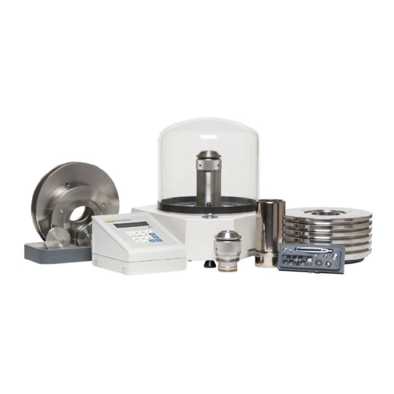
DH Instruments PG7601-SYS-AF Operation And Maintenance Manual (234 pages)
Gas Operated Piston Gauge Pressure Calibration System
Brand:
DH Instruments
| Category:
Measuring Instruments
| Size: 4 MB
Table of Contents
Table of Contents
3
Table of Contents
5
Tables
9
Figures
13
A B O U T T H I S M a N U al
13
Specifications
15
Overall System Specifications
15
Pressure Measurements
16
Piston Gauge Platform (Pg7601-Af)
16
Embedded Features
17
Measurement of Ambient and Instrument Conditions
18
Piston-Cylinder Modules (Pc-7100/7600-10-L, -50, -200)
19
Mass Set (Ms-7001-35-Af)
20
Pressure Controller (Ppc3-7M-Af)
21
Reference Vacuum Pump (D16B)
21
1 Introduction
15
S y S T E M a N D C O M P O N E N T O V E R V I E W a N D D E S C R I P T I on
23
System Overview (Pg7601-Sys-Af)
23
Figure 1. System, PG7601-SYS-AF, Standard Installation
23
Figure 2. System, PG7601-SYS-AF, Pneumatic Schematic
25
Figure 3. System, PG7601-SYS-AF, Communications Schematic
25
Piston Gauge Platform and Terminal (Pg7601-Af)
26
Figure 4. Piston Gauge Operating Principle
26
Figure 5. Platform, PG7601-AF, Rear View
27
Platform
27
Figure 6. PG Terminal Front Panel
28
Figure 7. PG Terminal Rear Panel
28
Pg Terminal
28
Piston-Cylinder Modules (Pc-7100/7600-10-L, -50, -200)
29
Figure 8. Piston-Cylinder Modules, PC-7100/7600-10-L, -50, -200
29
Mass Set (Ms-7001-35-Af)
30
Pressure Controller (Ppc3-7M-Af)
30
Figure 9. Mass Set, MS-7100-35-AF
30
Figure 10. Pressure Controller, PPC3-7M-AF, Front Panel
31
Figure 11. Pressure Controller, PPC3-7M-AF, Rear Panel
31
Reference Vacuum Pump (D16B)
32
Figure 12. Reference Vacuum Pump, D16B, Front and Side Views
32
3 Installation
33
Unpacking and Inspection
33
Unpacking and Inspection of Pg7601-Bas-Af Base System
33
Platform, Terminal and Bell Jar (Pg7601-Af)
33
Table 1. Base System, PG7601-BAS-AF, Packing Guide
33
Pressure Controller (Ppc3-7M-Af)
34
Reference Vacuum Pump (D16B)
34
Pressure Interconnections Kit (Pk-7601-P-Af)
34
Table 2. Platform, PG7601-AF, Packing List
34
Table 3. Pressure Interconnections Kit, PK-7601-P-AF, Packing List
34
Vacuum Interconnections Kit (Pk-7601-V-Af)
35
Documentation and Accessories
35
Unpacking and Inspection of Pg7601-Exc-Af Exchange Package
35
Table 4. Vacuum Interconnections Kit, PK-7601-V-AF, Packing List
35
Table 5. Base System Accessories Kit Packing List
35
Piston-Cylinder Modules (Pc-7100/7600-10-L, Pc-7100/7600-50, Pc-7100/7600-200) and Accessories
36
Mass Set (Ms-7001-35-Af)
36
Table 6. Exchange Pack, PG7601-EXC-AF, Packing Guide
36
Table 7. Piston-Cylinder Modules, PC-7100/7600-10-L, PC-7100/7600-50, PC-7100/7600-200, Packing List
36
Documentation and Accessories
37
Site Requirements
37
Table 8. Mass Set, MS-7001-35-AF, Packing List
37
Table 9. Exchange Pack Accessories Packing List
37
Physical Setup
39
Setting up the Platform
39
Setting up the Pressure Controller
40
System Pressure Interconnections
40
Setting up the Mass Set
41
Installing a Piston-Cylinder Module into the Platform
42
Figure 13. Piston-Cylinder Module Installation
42
Setting up the Reference Vacuum Pump and Vacuum Interconnections
43
Connecting Test Gas Supply
43
Connecting Control Vacuum Supply
44
Power up and Verification
44
Power up Platform and Pressure Controller
44
Check that On-Board Piston-Cylinder Module and Mass Set Digital Ids Are Correct
45
Set Local Gravity Value
45
Check/Set Security Level
45
Check Proper Operation of Ambient Condition Measurements
45
Turn on Autogen and Autorotate
46
Apply Supply Pressure
46
Apply Control Vacuum
46
Apply Reference Vacuum
46
Set a Gauge Mode Pressure, Check Autogen and Autorotate Functions
46
Check Piston Behavior Measurements
48
Check Reference Vacuum System and Absolute Mode Operation
48
Additional Precautions to Take to Make Good Pressure Measurements
50
4 General Operation
51
Operating Principles
51
Fundamental Operating Principle
51
Figure 14. Piston Gauge Operating Principle
51
Pressure Control, Manual and Automated
52
Pressure Ready/Not Ready Indication
53
Piston Position Ready/Not Ready
53
Piston Rotation Ready/Not Ready
54
Vacuum Reference Ready/Not Ready
54
Piston Position
55
Mass Loading Protocol
56
Figure 15. Piston Stroke and Zones
56
User Interface
59
Piston Gauge (System Interface)
59
Keypad Layout and Protocol
59
Figure 16. PG Terminal Keypad Layout
59
Main Run Screen
60
Figure 17. Platform MAIN Run Screen Display Fields
61
General Function/Menu Flow Chart
62
Sounds
62
Figure 18. RUN Screen Flow Chart
62
Pressure Controller
63
Keypad Layout and Protocol
63
Figure 19. Pressure Controller Keypad Layout
63
Direct Pressure Control Keys
64
Figure 20. Pressure Controller Direct Pressure Control Keys
64
Main Run Screen
65
Sounds
66
Figure 21. Pressure Controller MAIN Run Screen Display Fields
66
Direct Function Keys
67
Direct Function Keys Summary
67
P-C], View and Select Piston-Cylinder Modules
67
Table 10. Summary of PG7601-AF PG Terminal Direct Function Key Operations
67
Unit], Select Pressure Unit of Measure
69
Mode], Select Pressure Measurement Mode
70
System], View System Conditions Measurement Screens
71
First System Run Screen
71
Second System Run Screen
72
Ambient], View Ambient Conditions Measurements Screen
73
Head], Set Fluid Head Correction Height
74
Rotate], Manage Motorized Piston Rotation
76
2Pre-Decel
78
Gen], Manage Automated Pressure Generation
78
2Target
80
3Raise
80
4Ul
80
5Tol
81
6Refloat
81
Viewing and Setting Ppc3-7M-Af Com1 Port Settings
82
Res], Set Mass Loading Resolution
82
Set P], Set or Measure a Pressure
83
Set P] in Pressure to Mass Mode
85
Set P] in Mass to Pressure Mode
86
Commands for Zero Pressure, Ending Atest
87
Por M], Set Pressure to Mass or Mass to Pressure Operating Mode
87
And [ ], [←], Manual Control of Motorized Rotation
88
Setup] Menu, Manage Pressure Equation Variable Sources
89
Table 11. SETUP File Choices, Factory Preferred Choice and Normal Value
90
1Select
91
2View
91
3Edit
92
Special] Menu
95
1Pc/Ms>, Manage Metrological Element Digital Ids
96
Create Piston-Cylinder Module
97
Table 12. Piston-Cylinder Module Digital ID Fields
98
Edit Piston-Cylinder Module
100
View Piston-Cylinder Module
100
Delete Piston-Cylinder Module
101
Select the Active Piston-Cylinder Module
101
Add Mass Set
101
Table 13. Mass Set Digital ID Fields
102
Edit Mass Set
105
View Mass Set
105
Delete Mass Set
105
Select Mass Set
106
Add Mass Loading Bell
106
Table 14. Mass Loading Bell Digital ID Fields
106
Edit Mass Loading Bell
107
View Mass Loading Bell
108
Delete Mass Loading Bell
108
Select Mass Loading Bell
108
2Presu>, Customize Unit Function Selections
108
Table 15. Pressure Units of Measure Available
109
3Head>, Customize Fluid Head Functions
110
3Head>, <1Fluid
111
3Head>, <2Unit
111
3Head>, <3Atm
111
3Head>, <4Piston
112
4Prefs>, Set User Preferences
112
4Prefs>, <1Scrsvr
112
4Prefs>, <2Sound
113
4Prefs>, <3Time
113
4Prefs>, <4Id
113
4Prefs>, <5Level
114
Table 16. Security Levels - Functions NOT Executed Per Function/Level
116
5Remote>, Manage Remote Communication Interfaces
117
Com1, Com2 and Com3 (Rs232)
118
Ieee-488
118
Table 17. COM1, COM2 and COM3 Available Settings
118
Rs232 Self Test
119
External Barometer (Rpm) Communications (Com2)
119
External Vacuum Gauge Communications (Com2)
121
6Gl>, Set Value of Local Gravity
124
7Cal>, Manage Internal Measurement Sensor Calibrations
124
8Amh>, Operate Automated Mass Handler (Not Included)
124
9Reset>, Use System Resets
125
9Reset>, <1Sets
125
9Reset>, <2Units
126
9Reset>, <3Com
126
9Reset>, <4Cal
126
9Reset>, <5Setups
127
9Reset>, <6All
127
5 Remote Operation
129
Overview
129
Interfacing
129
Rs232 Interface
129
Com1
130
Com2 and Com3
130
Table 18. COM1 DB-9F Pin Designation
130
Table 19. COM2 and COM3 DB-9M Pin Designation
130
Ieee-488 (Gpib)
131
Commands
131
Command Syntax
131
Command Summary
131
Table 20. Command Summary
132
Error Messages
134
Table 21. Error Messages
134
Command Descriptions
135
Ieee Std. 488.2 Common and Status Commands
135
Pg7601-Af Commands
137
Status System
162
Status Reporting System
163
Status Byte Register
163
Table 22. Status Byte Register
163
Figure 22. Status Byte Register
163
Standard Event Register
164
Table 23. Standard Event Register
164
6 General Maintenance and Adjustments
167
Overview
167
Table 24. Mechanical Maintenance Procedures
167
Illustrated Parts Breakdown
168
Table 25. Top Level Illustrated Parts Breakdown (See Figure 23)
168
Figure 23. Top Level Illustrated Parts Breakdown for PG7601-SYS-AF
169
Table 26. PG7601 Illustrated Parts Breakdown for Mass Set, Cases, and Covers (See Figure 24)
170
Figure 24. PG7601 Illustrated Parts Breakdown for Mass Sets, Cases, and Covers
170
Table 27. PG7601 Illustrated Parts Breakdown for Piston Cylinders (See Figure 25)
171
Table 28. PG7601 Illustrated Parts Breakdown for Piston Cylinder Cases (See Figure 26)
171
Figure 25. PG7601 Illustrated Parts Breakdown for Piston Cylinders
172
Figure 26. PG7601 Illustrated Parts Breakdown for Piston Cylinder Cases
172
Table 29. PG7601 Illustrated Parts Breakdown for PG Main Board (See Figure 27)
173
Figure 27. PG7601 Illustrated Parts Breakdown for PG Main Board
173
Table 30. PG7601 Illustrated Parts Breakdown for PG Base Underside (See Figure 28)
174
Figure 28. PG7601 Illustrated Parts Breakdown for PG Base Underside
175
Table 31. PG7601 Illustrated Parts Breakdown for PG Base Outside (See Figure 29)
176
Figure 29. PG7601 Illustrated Parts Breakdown for PG Base Outside
176
Table 32. PG7601 Illustrated Parts Breakdown for PG Terminal Outside (See Figure 30)
177
Figure 30. PG7601 Illustrated Parts Breakdown for PG Terminal Outside
177
Table 33. PG7601 Illustrated Parts Breakdown for PG Terminal Inside (See Figure 31)
178
Figure 31. PG7601 Illustrated Parts Breakdown for PG Terminal Inside
178
Table 34. PG7601 Illustrated Parts Breakdown for PPC3 Outside (See Figure 32)
179
Figure 32. PG7601 Illustrated Parts Breakdown for PPC3 Outside
180
Table 35. PG7601 Illustrated Parts Breakdown for PPC3 Pneumatic Module (See Figure 33)
181
Figure 33. PG7601 Illustrated Parts Breakdown for PPC3 Pneumatic Module
182
Table 36. PG7601 Illustrated Parts Breakdown for PPC3 Inside (See Figure 34)
183
Figure 34. PG7601 Illustrated Parts Breakdown for PPC3 Inside
183
Table 37. PG7601 Illustrated Parts Breakdown for PPC3 Manifold Detail (See Figure 35)
184
Figure 35. PG7601 Illustrated Parts Breakdown for PPC3 Manifold Detail
184
Table 38. PG7601 Illustrated Parts Breakdown for PK-7601-P-AF (See Figure 36)
185
Figure 36. PG7601 Illustrated Parts Breakdown for PK-7601-P-AF
185
Table 39. PG7601 Illustrated Parts Breakdown for Accessories Kit (See Figure 37)
186
Figure 37. PG7601 Illustrated Parts Breakdown for Accessories Kit
186
Piston-Cylinder Modules
187
Disassembly and Reassembly
187
Pc-7100/7600-10-L (10 Kpa/Kg) Disassembly and Reassembly
188
Figure 38. 10 Kpa/Kg Piston-Cylinder Module (Expanded View)
191
Figure 39. Gas Piston-Cylinder Module Sleeve Nut Tool
191
Pc-7100/7600-10-L (10 Kpa/Kg) Piston Insertion Tool
192
Figure 40. 10 Kpa/Kg Piston Insertion Tool
192
Pc-7100/7600-50 and -200 (50 and 200 Kpa/Kg) Disassembly and Reassembly
194
Cleaning Piston-Cylinders
196
Overview
196
Figure 41. 50, 200 Kpa/Kg Gas Piston-Cylinder Modules (Expanded View)
196
Water/Detergent Method
197
Quick Method
198
Lubricating Piston-Cylinder Modules
199
Platform
200
Piston Position Detection Adjustment
200
Figure 42. Piston-Cylinder Module Lubrication Chart
200
Drive Belt Replacement
201
Disassembly and Reassembly of Pg7601-Af
201
Platform
201
Terminal
202
Table 40. PG7601-AF Mounting Post Wire Colors, Description and Location
202
Adjusting Pressure Controller Internal Pressure Sensor
203
Reference Vacuum Pump
205
Check/Top off Oil Level
205
Drain and Refill Oil
205
Reloading Embedded Software into Platform or Pressure Controller Flash Memory
206
Storage and Shipping
206
Short and Long Term Storage
206
Preparation for Shipping
207
Piston-Cylinder Modules
207
Mass Set
207
Platform
207
Pressure Controller
208
Vacuum Pump
208
7 Maintenance of Traceability and Recalibration
209
Principles of System Traceability Maintenance
209
Local Metrological Maintenance between Recalibrations
209
Overview
209
Platform, Adjust On-Board P, T, H Sensors
209
Table 41. Metrological Maintenance Procedures
209
Barometric Pressure Sensor
210
Ambient Temperature Sensor
211
Relative Humidity Sensor
212
Recalibration
212
Overview
212
Calibration of Piston-Cylinder Modules
213
Preparing for Calibration
213
Updating Piston-Cylinder Module Digital Ids
213
Table 42. Recalibration Requirements
213
Calibration of Mass Set
214
Preparing for Calibration
214
Updating Mass Set Digital ID
214
Calibration of Piston-Cylinder Module Temperature Sensor
214
Overview
214
Procedure
215
Calculating and Updating Piston-Cylinder Temperature Sensor Information
215
Calibration of Residual Vacuum Gauge
216
Overview
216
Procedure
217
Calculating and Updating Vacuum Gauge Calibration Information
218
Figure 43. Vacuum Gauge Calibration Setup
218
Managing Metrological Element Digital Ids with Caltool™ for Pg7000 Software
219
Overview
219
Operation
219
Getting Started
220
Processing a New Digital ID File (after Recalibration)
221
Storing Digital Ids from the Pg7601-Af in the Caltool Database or to *.DID File
221
Archiving Digital Ids
222
8 Troubleshooting
223
Overview
223
Table 43. Troubleshooting Checklist
223
9 Appendix
227
9. Appendix Conversion of Numerical Values
227
Pressure
227
Defined Pressure Calculations
227
Table 44. Pressure Unit of Measure Conversions
227
Table 45. Defined Pressure Calculation Variables
228
Fluid Head Components
229
Fluid Heads
229
Pg7601-Af
229
Overall Fluid Head Correction
231
Glossary
231
Warranty Statement
233
Table 46. DHI Authorized Service Providers
233
Advertisement
Advertisement
Related Products
DH Instruments PG7601 - V2.03
DH Instruments PG7601 - V2.07
DH Instruments PG7601 - V3.0
DH Instruments PG7607 - 2006
DH Instruments PG7607 - 2008
DH Instruments PG7607
DH Instruments PG7601
DH Instruments PG7000 - V2.03
DH Instruments PG7102 - V2.07
DH Instruments PG7000 - V3.0
DH Instruments Categories
Controller
Measuring Instruments
Racks & Stands
Cables and connectors
Accessories
More DH Instruments Manuals
Login
Sign In
OR
Sign in with Facebook
Sign in with Google
Upload manual
Upload from disk
Upload from URL