
Related Manuals for DH Instruments AMH-100


Summary of Contents for DH Instruments AMH-100
- Page 1 AMH-38™/AMH-100™ Automated Mass Handling System for PG7000 Piston Gauges Operation and Maintenance Manual © 2007 DH Instruments, a Fluke Company...
- Page 2 The fidelity of subsequent translations cannot be guaranteed. In case of conflict between the English version and another language version, the English version takes precedence. DH Instruments, DH, DHI, AMH-38, AMH-100, PG7000, PG7xxx are trademarks of DH Instruments, a Fluke Company, registered and otherwise.
-
Page 3: Table Of Contents
2.3.2.6 CONNECTING AN EXTERNAL REFERENCE VACUUM GAUGE (AMH-38 ONLY) ......13 PREPARING THE PG7000 PLATFORM ....................13 2.4.1 PREPARING PG7102, PG7202, PG7302 PLATFORM HARDWARE FOR AMH-100........13 2.4.2 PREPARING PG7601 PLATFORM HARDWARE FOR AMH-38 ..............13 2.4.3 VERIFYING PG7000 EMBEDDED SOFTWARE VERSION FOR AMH SUPPORT........14 CHECKING THE PG7000 PISTON-CYLINDER MODULES FOR AMH OPERATION......14... - Page 4 AMH-38™ AND AMH-100™ OPERATION AND MAINTENANCE MANUAL 3.2.5 MAKING AND BREAKING THE REFERENCE VACUUM (AMH-38 ONLY)..........27 3.2.6 ACCESSING THE PG7000 PISTON-CYLINDER MODULE ...............27 3.2.7 INDICATOR LED............................27 3.2.8 ERROR MESSAGES ...........................28 R E M O T E O P E R A T I O N ............3 1 OVERVIEW ............................31...
- Page 5 Table 5. AMH Troubleshooting Checklist ....................35 Table 6. DHI Authorized Service Providers ....................37 Figure 1. AMH-38 Automated Mass Handler....................2 Figure 2. AMH-100 Automated Mass Handler..................... 3 Figure 3. PG7601 Vacuum Plate Detail ..................... 13 Figure 4. Piston Cap Inspection......................... 15 Figure 5.
- Page 6 AMH-38™ AND AMH-100™ OPERATION AND MAINTENANCE MANUAL © 2007 DH Instruments, a Fluke Company Page IV...
-
Page 7: A B O U T T H I S M A N U Al
ABOUT THIS MANUAL This manual is designed to be used in conjunction with the PG7000 Piston Gauges Manual, to assist in the set up, operation and maintenance of an AMH-38 or AMH-100 automated mass handling system. Manual Conventions (CAUTION) is used in throughout the manual to identify user warnings and cautions. - Page 8 AMH-38™ AND AMH-100™ OPERATION AND MAINTENANCE MANUAL © 2007 DH Instruments, a Fluke Company Page VI...
-
Page 9: I N T R O D U C T I On
AMH-100 is compatible with PG7201, PG7202, PG7302 and PG7307 Platforms and handles a mass set of nominally 40, 60, 80 or 100 kg. It does not include a vacuum chamber so the masses are always in ambient pressure conditions. -
Page 10: Location And Description Of The Components
AMH-38™ AND AMH-100™ OPERATION AND MAINTENANCE MANUAL LOCATION AND DESCRIPTION OF THE COMPONENTS 1.2.1 AMH-38 KF-40 vacuum connections (2) AMH status indication LED Lifting handles (2) RS232 Port, COM1 Mass lifter and pneumatic actuation DC power connection solenoid valves Drive air pressure connection... -
Page 11: Amh-100
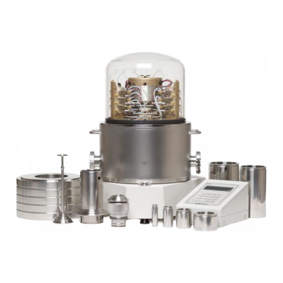
Drive air pressure connection Main mass manipulation column RS232 Port, COM1 Bubble level DC power connection Mass lifter and pneumatic AMH status indication LED actuation cover Figure 2. AMH-100 Automated Mass Handler Page 3 © 2007 DH Instruments, a Fluke Company... -
Page 12: Specifications
AMH-38™ AND AMH-100™ OPERATION AND MAINTENANCE MANUAL SPECIFICATIONS Power Requirements: 15 VDC @ 2 A, 30 W max. consumption 15 to 35 ºC Operating Temperature: AMH-38: 41 cm H x 37 cm W x 38 cm D (16.3 in. x 14.6 in. x 15 in.) -
Page 13: P R E P A R A T I O N F O R O P E R A T I On
2. PREPARATION FOR OPERATION UNPACKING AND INSPECTION AMH-38 and AMH-100 are delivered, along with their standard accessories, in a corrugated container with foam cut outs to hold items in place. Remove all parts from the shipping box. Be sure not to lose or discard the Accessory Kit. -
Page 14: Table 2. Ahm-100 Parts List
AMH-38™ AND AMH-100™ OPERATION AND MAINTENANCE MANUAL Table 2. AHM-100 Parts List DESCRIPTION PART # 1 ea. AHM-100 Automated Mass Handler 402062 or 402062-CE Accessory kit including: 402094 or 402094-CE 1 ea. Operation and Maintenance Manual 550133 1 ea. 15 VDC Power Supply 103986 1 ea. -
Page 15: Site Requirements
GAS SUPPLIES AMH-38 requires a compressed air source and a vacuum source (see Sections 2.2.2.1, 2.2.2.2). AMH-100 requires a compressed air source only (see Section 2.2.2.1). 2.2.2.1 DRIVE AIR SUPPLY The drive air supply provides power to operate the mass lifter and the binary mass selector pins (see Section 3.1). -
Page 16: Vacuum Supply (Amh-38 Only)
AMH-38™ AND AMH-100™ OPERATION AND MAINTENANCE MANUAL 2.2.2.2 VACUUM SUPPLY (AMH-38 ONLY) The vacuum supply is necessary for AMH-38 operation when there is vacuum in the AMH-38 vacuum chamber and bell jar (absolute by vacuum mode PG7601 operation). The vacuum supply assures that the binary mass selection pins remain in the correct position and evacuates internal AMH volumes to minimize the likelihood of leaks into the reference vacuum. -
Page 17: General Considerations
SETTING UP THE AMH FOR OPERATION 2.3.1 GENERAL CONSIDERATIONS AMH-100 requires only three connections: drive air supply, electrical power, and RS232 cable for communications with PG7000 Platform. Consider these connections when setting up the AMH-100. AMH-38 requires at least three connections: drive air supply, electrical power, and RS232 cable for communications with PG7000 Platform. - Page 18 AMH-38™ AND AMH-100™ OPERATION AND MAINTENANCE MANUAL To use the supplied accessories to make the AMH drive air supply connection proceed as follows: Connect the quick-connector to one end of the PFA tube. Loosen the 1/8 in. Swage nut on the assembly slightly. Slip the PFA tube into the nut until it stops.
-
Page 19: Connecting The Drive Vacuum Supply (Amh-38 Only)
When power is connected, the green LED near the electrical connector should light and not flash. If the LED flashes, see Section 3.2.7. If the LED doesn’t light, and you are sure power is connected, contact your DHI Authorized Service Provider. Page 11 © 2007 DH Instruments, a Fluke Company... -
Page 20: Connecting Pg7000 Platform Communications
AMH-38™ AND AMH-100™ OPERATION AND MAINTENANCE MANUAL 2.3.2.4 CONNECTING PG7000 PLATFORM COMMUNICATIONS Locate the 9 pin D-sub cable delivered with the AMH accessories. The communications connection configuration depends upon whether the PG7000 is being used with a PPC automated pressure controller. -
Page 21: Connecting An External Reference Vacuum Gauge (Amh-38 Only)
AMH-100 seating holes. When AMH-100 is used, the bubble level on the AMH-100 center plate is used to level the PG7000 system. Retain the casting level in case of future use of the platform without the AMH accessory. -
Page 22: Verifying Pg7000 Embedded Software Version For Amh Support
AMH-38™ AND AMH-100™ OPERATION AND MAINTENANCE MANUAL 2.4.3 VERIFYING PG7000 EMBEDDED SOFTWARE VERSION FOR AMH SUPPORT To use a PG7000 Platform with AMH, the PG7000 Platform embedded software must support AMH. PG7000 embedded software versions 2.05 or higher support AMH. -
Page 23: Checking The Piston Stop Bushing
The other cases contain the main masses of 6.2 (AMH-38) or 10 kg (AMH-100) (see PG7000 Operation and Maintenance Manual, Inspecting Contents, Mass Set for mass set composition detail). Each mass is packed in a sealed plastic bag and then placed in a protective shipping insert. -
Page 24: Figure 7. Amh Mass Set
SHOWN IS THE MS-AMH-38 MASS SET FOR THE AMH-38 MASS HANDLER. SMALLER MASS SETS MAY INCLUDE LESS MAIN MASS DISCS. MASS SETS FOR THE AMH-100 MASS SET ARE IDENTICAL TO AMH-38 BUT THE MAIN MASSES ARE LARGER 10 KG DISCS AND A 7TH BINARY MASS TUBE OF 6.2 KG IS INCLUDED. -
Page 25: Initial Start Up/Verification
(see Section 3.1). When this step is complete, the AMH mass handler is ready to be installed on the PG7000 Platform (see Section 3.2.1). Page 17 © 2007 DH Instruments, a Fluke Company... - Page 26 AMH-38™ AND AMH-100™ OPERATION AND MAINTENANCE MANUAL © 2007 DH Instruments, a Fluke Company Page 18...
-
Page 27: O P E R A T I O
Numerical reference in this section refers to Figure 8. The purpose of the AMH-38 or AMH-100 system is to automatically load specified values of mass onto the PG7000 piston. This is accomplished by lifting the complete mass set up off and above the piston- cylinder to the mass selection position, selecting the individual masses to be loaded and retained, and then placing the masses to be loaded back onto the piston. - Page 28 AMH-38™ AND AMH-100™ OPERATION AND MAINTENANCE MANUAL 4. Binary mass tube selection pins(3): The binary mass selection pins are used to retain the binary mass tubes that are not to be loaded onto the piston. Three pins for each mass are located in a circular pattern around the top of each mass.
-
Page 29: Figure 8. Amh Schematic/Operating Principle
5. Mass lifting assembly 12. Piston cap 6. Lifting ledge on mass lifting shaft 13. Main mass column 7. Electronics and electrical controls 14. Main masses Figure 8. AMH Schematic/Operating Principle Page 21 © 2007 DH Instruments, a Fluke Company... -
Page 30: Operation
AMH-38™ AND AMH-100™ OPERATION AND MAINTENANCE MANUAL OPERATION Once the AMH mass set has been installed (see Section 2.6) and the AMH mass handling system has been initialized (see Section 2.7) and installed, regular operation of the AMH is controlled by the P7000 Platform in response to local commands entered on the PG Terminal or remote commands received over the PG7000 Platform’s COM1 or IEEE-488 interface. -
Page 31: Installing Amh-38
AMH-38 vacuum chamber, lift the AMH-38 above the PG7601 platform and masses. Center it over the mass load and gently lower it down until the bottom circumference of the AMH-38 vacuum chamber reaches the PG7601 vacuum Page 23 © 2007 DH Instruments, a Fluke Company... -
Page 32: Installing Amh-100
AMH feet enter the holes in the PG7000 Platform. Assure that all three feet fully enter and seat in the platform holes. Tighten the platform set screws using a 2.5 mm allen wrench provided in the AMH-100 accessories, one for each of the feet. -
Page 33: Removing The Amh Mass Handler From The Pg7000 Platform
NOTE THAT SHAFT HAS A LEFT HAND THREAD SO IT MUST BE ROTATED COUNTER-CLOCKWISE TO TIGHTEN IT. Use the 3 mm allen wrench supplied in the AMH-100 accessories to tighten the assembly until you feel the masses begin to rotate. -
Page 34: Regular Mass To Pressure Or Pressure To Mass Operation
Lift the AMH-100 off of the PG7000 Platform: Grasping the AMH-100 by the horizontal platform in its middle, lift the AMH-100 straight up until it clears the masses and set it on a flat surface. The AMH-100 mass handler weighs about 12 kg (25 lb.). -
Page 35: Making And Breaking The Reference Vacuum (Amh-38 Only)
3.2.7 INDICATOR LED There is a green indicator LED located on AMH-38 and AMH-100 near the power supply connection. It is on the rear electrical, vacuum chamber pass through of AMH-38 and on the top cover of AMH-100 (see Figures 1, 2). -
Page 36: Error Messages
AMH-38™ AND AMH-100™ OPERATION AND MAINTENANCE MANUAL 3.2.8 ERROR MESSAGES The AMH mass handler can inform the PG7000 of certain error conditions. An AMH error condition is indicated on the PG Terminal by an error message and listing of the error number on the bottom right hand of the display. - Page 37 0.4 kg binary mass pin disengage valve (VLV#11) not <AMH valve failure> sensed. <AMH valve failure> 0.2 kg binary mass pin disengage valve (VLV#3) not sensed. 0.1 kg binary mass pin disengage valve (VLV#9) not sensed. <AMH valve failure> Page 29 © 2007 DH Instruments, a Fluke Company...
- Page 38 AMH-38™ AND AMH-100™ OPERATION AND MAINTENANCE MANUAL © 2007 DH Instruments, a Fluke Company Page 30...
-
Page 39: R E M O T E O P E R A T I O
PG7000 Platform, for example a command to clear the AMH and load all the mass on the piston. These commands are listed in the PG7000 Operation and Maintenance Manual, Remote Operation along with the other PG7000 remote commands. Page 31 © 2007 DH Instruments, a Fluke Company... - Page 40 AMH-38™ AND AMH-100™ OPERATION AND MAINTENANCE MANUAL © 2007 DH Instruments, a Fluke Company Page 32...
-
Page 41: M A I N T E N A N C E A N D A D J U S T M E N T
If AMH returns no errors and no operational issues are observed, no regular maintenance is required. To avoid any planned downtime, an AMH overhaul is recommended every 10000 hours of operation or three years. Contact a DHI Authorized Service Provider to have this service performed. Page 33 © 2007 DH Instruments, a Fluke Company... - Page 42 AMH-38™ AND AMH-100™ OPERATION AND MAINTENANCE MANUAL © 2007 DH Instruments, a Fluke Company Page 34...
-
Page 43: T R O U B L E S H O O T I N
PG7000 Platform. 2.7 AMH masses rock back and forth With AMH-100, check that there is no foreign when lifted to the mass selection matter in the column holes in the platform and position. the AMH column feet are fully engaged with feet set screws tightened. - Page 44 AMH-38™ AND AMH-100™ OPERATION AND MAINTENANCE MANUAL © 2007 DH Instruments, a Fluke Company Page 36...
-
Page 45: Warranty Statement
7. WARRANTY STATEMENT WARRANTY STATEMENT Except to the extent limited or otherwise provided herein, DH Instruments, a Fluke Company (DHI) warrants for one year from purchase, each new product sold by it or one of its authorized distributors, only against defects in workmanship and/or materials under normal service and use. Products which have been changed or altered in any manner from their original design, or which are improperly or defectively installed, serviced or used are not covered by this warranty. - Page 46 AMH-38™ AND AMH-100™ OPERATION AND MAINTENANCE MANUAL © 2007 DH Instruments, a Fluke Company Page 38...
Need help?
Do you have a question about the AMH-100 and is the answer not in the manual?
Questions and answers