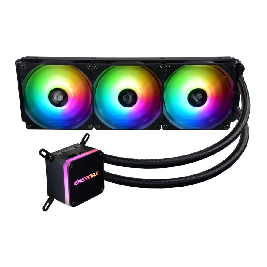
ENERMAX LIQMAX III Manual
- User manual (31 pages) ,
- User manual (33 pages) ,
- User manual (44 pages)
Advertisement
Specification
| Model | ELC-LMT120-ARGB | ELC-LMT240-ARGB ELC-LMT240-W-ARGB | ELC-LMT360-ARGB ELC-LMT360-W-ARGB | ||
| CPU Socket | Intel® LGA 1700/1200/115x/2066/2011/2011-3/1366 AMD® AM5/AM4/AM3+/FM2+/FM1 | ||||
| Material | Copper Base with Aluminum Radiator | ||||
| Pump | Bearing | Ceramic Bearing | |||
| MTBF | 50,000 hrs | ||||
| Motor Speed | 3100 RPM ± 10% | ||||
| Rated Voltage | 12 V | ||||
| Rated Current - Pump | 0.4 A *or 0.53A if not connected to 3 pin ARGB connector (5V/D/-/G) | ||||
| Water block | Rated Current - RGB LED | 0.18 A | |||
| Radiator | Dimension | 154 x 120 x 27 mm | 274 x 120 x 27 mm | 394 x 120 x 27 mm | |
| Tube | Material | Rubber | |||
| Length | 400 mm | ||||
| Weight (W/O fan) | 690 g | 795 g | 968 g | ||
| Fan | Dimension | 120 x 120 x 25 mm | |||
| MTTF | 50,000 hrs | ||||
| Speed | 500~1600 RPM | ||||
| Rated Voltage | 12 V | ||||
| Rated Current - Fan | 0.17 A | ||||
| Rated Voltage RGB LED | 5V | ||||
| Rated Current - RGB LED | 0.36 A | ||||
| Air Flow | 22.5~72.1 CFM | ||||
| Stac Pressure | 0.2~1.98 mm-H2O | ||||
| Noise Level | 14~27 dBA | ||||
| Connector | 4 pin PWM connector 3 pin ARGB connector (5V/D/-/G) | ||||
| Thermal Grease | Dow Corning® TC-5121C | ||||
* Note: An addressable RGB mainboard with 5V header is needed to provide full lighng capability. In stand-alone mode, only the water block is illuminated with the Racing-Rainbow effect.
LIQMAX III ARGB 120 - Part List

LIQMAX III ARGB 240 - Part List

LIQMAX III ARGB 360 - Part List

Intel Installation
- Aattch the fan and the radiator to the chassis.

- Install the Intel clip to the pump.

-
- Insert the posion screws into the proper holes on the back plate. Then use the washers to fix the posion screws.
《If your CPU plaorm is Intel 1700, please skip to step 3-2》
《If your CPU plaorm is Intel 2011/2011-3/2066, please skip to step 4-2》

- Insert the LGA1700 posion screws into the proper holes on the back plate. Then use the washers to fix the posion screws.

- Insert the posion screws into the proper holes on the back plate. Then use the washers to fix the posion screws.
-
- Install the Intel back plate on to the back of motherboard; fix the back plate with the stand-off.
*LGA 1700/1200/115X/1366

- Tighten the Intel LGA2011/2011-3/2066 screw to the motherboard.
*Intel LGA 2011/2011-3/2066

- Install the Intel back plate on to the back of motherboard; fix the back plate with the stand-off.
- Apply the thermal grease evenly on the CPU surface.

- Remove the protect film from the cold-plate.

- Place the pump on the CPU and ghten the spring screws unl all four corners are secured.

- Connect the pump power connector to the motherboard.
Notice: If you recognize that your mainboard's CPU fan or PWM sockets do not provide enough voltage to power the pump, please use the included SATA adaptor and connect the pump directly to your PSU.

- Connect the fan connector to the motherboard.


AMD Installation
- Aach the fan and the radiator to the chassis.

- Install the AMD clip to the pump

- Remove the original screws and place the back plate back into position.

- Tighten the AMD screw to the AMD stock back plate(included with the motherboard).

- Apply the thermal grease evenly on the CPU surface.

- Remove the protect film from the cold-plate.

- Place the pump on the CPU and ghten the spring screws unl all four corners are secured.

- Connect the pump power connector to the motherboard.
Noce: If you recognize that your mainboard's CPU fan or PWM sockets do not provide enough voltage to power the pump, please use the included SATA adaptor and connect the pump directly to your PSU.

- Connect the fan connector to the motherboard.


Motherboard Sync

Connect the sync cable to a supported motherboard with ARGB header
RGB Control Box
 For non-addressable RGB motherboard
When you install th cooler onto the motherboard, please connect the RGB Sync cable to the water block, and then connect the power connectors to RGB control box. Meanwhile, connect the SATA power cable to PC power supply SATA connector.


The 4 LED colors indicate the different modes: GREEN (Light Effect), RED (Effect Speed), BLUE (Brightness), YELLOW (Auto-run).
- Press "M" unl you reach the Light Effect Mode (GREEN).
- To change the effect, press the
![]() or
or ![]() buon.
buon. - 10 pre-set light effects:
- Racing-Rainbow (Default)
- Breathing-Rainbow
- Flash-Rainbow
- Overlaying-Rainbow
- Flow-Rainbow
- Colors auto-run (8 colors)
Press![]() for 3 seconds to fix the current color. Press
for 3 seconds to fix the current color. Press ![]() for 3 seconds again to return to the Colors auto-run effect.
for 3 seconds again to return to the Colors auto-run effect. - Ripple auto-run (8 colors)
Press![]() for 3 seconds to fix the current color. Press
for 3 seconds to fix the current color. Press ![]() for 3 seconds again to return to the Flash auto-run effect.
for 3 seconds again to return to the Flash auto-run effect. - Overlaying-RED
- Overlaying-GREEN
- Overlaying-BLUE
- Pressing
![]() for 3 seconds will return to the default "Racing-Rainbow" effect.
for 3 seconds will return to the default "Racing-Rainbow" effect.
 or
or  buon.
buon.
- Press "M" unl you reach the Effect Speed Mode (RED).
- To change the effect speed, press the
![]() or
or![]() buon.
buon.

- Press "M" unl you reach the Brightness Mode (BLUE).
- To adjust the brightness, press the
![]() or
or ![]() buon.
buon. - Press "M" in any mode for 3 seconds to turn-off the light. Press "M" again to turn on the light and connue with the previous effect.
Documents / ResourcesDownload manual
Here you can download full pdf version of manual, it may contain additional safety instructions, warranty information, FCC rules, etc.
Advertisement


Need help?
Do you have a question about the LIQMAX III and is the answer not in the manual?
Questions and answers