Sign In
Upload
Download
Table of Contents
Contents
Add to my manuals
Delete from my manuals
Share
URL of this page:
HTML Link:
Bookmark this page
Add
Manual will be automatically added to "My Manuals"
Print this page
×
Bookmark added
×
Added to my manuals
Manuals
Brands
AUSTRALIAN MONITOR Manuals
Amplifier
AM42P
Installation and operation manual
AUSTRALIAN MONITOR AM42P Installation And Operation Manual
Amp series constant voltage installation audio power amplifiers
Hide thumbs
1
2
3
4
5
6
7
8
9
10
11
12
13
14
15
16
Table Of Contents
17
page
of
17
Go
/
17
Contents
Table of Contents
Bookmarks
Table of Contents
Installation and Operation Manual
Important Safety Information
Protection Features
Amplifier Block Diagram
Controls, Connectors and Indicators
Front Panel
Power Indicator
Protect Indicator
Clip Indicator
Power Switch
Top Panel
Limiter Switch
Rear Panel
Level Control
Signal Input
Speaker Outputs
Installation
Power Requirements
Input Wiring
Output Wiring
Operation
Maintenance
Specifications
Specifications (Cont)
Advertisement
Quick Links
1
Installation and Operation Manual
2
Amplifier Block Diagram
3
Controls, Connectors and Indicators
4
Speaker Outputs
5
Signal Input
6
Maintenance
7
Specifications
Download this manual
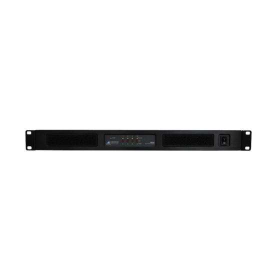
INSTALLATION AND OPERATION MANUAL
AMP SERIES
CONSTANT VOLTAGE INSTALLATION
AM42P
AUDIO POWER AMPLIFIERS
AM41P
AM22P
AM21P
Table of
Contents
Previous
Page
Next
Page
1
2
3
4
5
Advertisement
Table of Contents
Need help?
Do you have a question about the AM42P and is the answer not in the manual?
Ask a question
Questions and answers
Related Manuals for AUSTRALIAN MONITOR AM42P
Amplifier AUSTRALIAN MONITOR AMC+30 Installation And Operation Manual
Amc+ series mixer amplifiers (17 pages)
Amplifier AUSTRALIAN MONITOR AMC+120 Installation And Operation Manual
Mixer amplifier (29 pages)
Amplifier AUSTRALIAN MONITOR AMC30 Installation And Operation Manual
Amc series (12 pages)
Amplifier AUSTRALIAN MONITOR AM1600 Operation Manual
Audio power amplifier (20 pages)
Amplifier AUSTRALIAN MONITOR AM1600 Owner's Manual
Professional audio power amplifier (8 pages)
Amplifier Australian Monitor AMIS60 Series Service Manual
Installation seres (26 pages)
Amplifier Australian Monitor AMIS120XL Series Service Manual
Acm120xl is a 120 watt mixer amplifier (33 pages)
Amplifier Australian Monitor AMIS250 Series Service Manual
(26 pages)
Amplifier AUSTRALIAN MONITOR AMIS26 Installation And Operation Manual
2 input, 6 output distribution amplifier (13 pages)
Amplifier AUSTRALIAN MONITOR AM2200NG Installation And Operation Manual
Amng series, audio power amplifiers (13 pages)
Amplifier AUSTRALIAN MONITOR AMC+ SERIES Installation And Operation Manual
30w/60w/120w/250w (12 pages)
Amplifier AUSTRALIAN MONITOR AMC+120P Installation And Operation Manual
Amc+ series (15 pages)
Amplifier AUSTRALIAN MONITOR AMD100 Installation And Operation Manual
Amd series (21 pages)
Amplifier AUSTRALIAN MONITOR AMD200 Installation And Operation Manual
Amd series (21 pages)
Amplifier AUSTRALIAN MONITOR AM22P Installation And Operation Manual
Amp series constant voltage installation audio power amplifiers (17 pages)
Amplifier AUSTRALIAN MONITOR AM21P Installation And Operation Manual
Amp series constant voltage installation audio power amplifiers (17 pages)
This manual is also suitable for:
Am22p
Am41p
Am21p
Table of Contents
Print
Rename the bookmark
Delete bookmark?
Delete from my manuals?
Login
Sign In
OR
Sign in with Facebook
Sign in with Google
Upload manual
Upload from disk
Upload from URL


Need help?
Do you have a question about the AM42P and is the answer not in the manual?
Questions and answers